
EN
TR
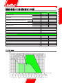
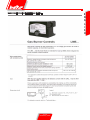
MINICOMIST 7
MINICOMIST 11
ORIGINAL INSTRUCTIONS ARE (IT)
ORİJİNAL KULLANIM KILAVUZU (IT)
0006081159_201102
Kullanım
talimatları kılavuzu.
Manual
instructions for use


0006081159_201102
- Before using the burner for the rst time please carefully read the chapter “WARNINGS NOTES FOR THE USER : HOW TO USE
THE BURNER SAFELY” in this instruction manual, which is an integral and essential part of the product. The works on the burner
and on the esystem have to be carried out only by competent people.
- Read carefully the instructions before starting the burner and service it.
- The system electric feeding must be disconnected before starting working on it.
- If the works are not carried out correctly it is possible to cause dangerous accidents.
E
N
G
L
I
S
H
T
ü
r
k
ç
e
- Brülörü ilk defa kullanmadan önce lütfen ürünün bütünleşik ve lüzumlu bir parçası olarak brülörle beraber verilen bu kullanma kılavuzu
içinde yer alan “BRÜLÖRÜN GÜVENLE KULLANILMASI İÇİN KULLANICIYA UYARI NOTLARI” bölümünü dikkatle okuyunuz. Brülör
ve sistem üzerindeki çalışmalar sadece yetkili personel tarafından yapılmalıdır.
- Brülörü çalıştırmadan veya onarımına başlamadan önce kullanma kılavuzunu dikkatle okuyunuz.
- Brülör üzerinde onarıma başlamadan önce sistemin elektrik beslemesi kesilmelidir.
- Talimatlara titizlikle uyulmayıp, çalışmalar düzgün yürütülmediği tehlikeli kazaların oluşması mümkündür.

E
N
G
L
I
S
H
4 / 18
0006081159_201102
BALTUR S.p.A.
Via Ferrarese 10 - 44042 CENTO (Ferrara) ITALIA
Tel. 051.684.37.11 Fax 051.685.75.27/28
(International Tel. ++39.051.684.37.11 - Fax ++39.051.683.06.86)
http://www.baltur.it - http://www.baltur.com - E-MAIL info@baltur.it
04/01/2010
Declaration of Conformity
We declare that our products
BPM...; BGN…; BT…; BTG…; BTL…; TBML...; Comist…;
GI…; GI…Mist; Minicomist…; PYR…; RiNOx…; Spark...;
Sparkgas...; TBG...;TBL...; TBML ...; TS…; IBR...; IB...
(Variant: … LX, for low NOx emissions)
Description:
forced air burners of liquid, gaseous and mixed fuels for residential and
industrial use meet the minimum requirements of the European Directives:
90/396/CEE ...............................................(D.A.G.)
89/336/CEE - 2004/108/CE ........................(C.E.M.)
73/23/CEE – 2006/95/CE ...........................(D.B.T.)
2006/42/CEE .............................................(D.M.)
and conform to European Standards:
UNI EN 676:2008 (gas and combination, gas side)
UNI EN 267:2002 (diesel and combination, diesel side)
These products are therefore marked:
0085
Dr. Riccardo Fava
Managing Director / CEO
!
Important / note
i
Information
I
Warning / Attention
Indice analitico
COMBINED DUNGS GAS VALVE ...............................................................................................................................................17
CHECKS PRIOR LIGHT OIL FIRING - DUAL FUEL BURNER’S FIRING INDICATION - ELECTRICAL CONNECTIONS ........11
FITTING THE BURNER TO THE BOILER AND CONNECTING THE GAS PIPE ........................................................................9
GAS BURNER CONTROL DEVICE GAS LME 22.. .....................................................................................................................15
MAINTENANCE ...........................................................................................................................................................................12
NOTES ON USE OF PROPANE (L.P.G.) .....................................................................................................................................13
STARTING UP AND REGULATION WITH LIGHT OIL - STARTING UP AND REGULATION WITHMETHANE GAS .................12
TECHNICAL DATA AND OVERALL DIMENSIONS ......................................................................................................................7
ELECTRIC DIAGRAM ...................................................................................................................................................................34

E
N
G
L
I
S
H
5 / 18
0006081159_201102
FOREWORD
These warning notes are aimed at ensuring the safe use of the compo-
nents of heating systems for civil use and the production of hot water.
They indicate how to act to avoid the essential safety of the components
being compromised by incorrect or erroneous installation and by improper
or unreasonable use. The warning notes provided in this guide also seek
to make the consumer more aware of safety problems in general, using
necessarily technical but easily understood language. The manufacturer
is not liable contractually or extra contractually for any damage caused
by errors in installation and in use, or where there has been any failure to
follow the manufacturer’s instructions.
GENERAL WARNING NOTES
• The instruction booklet is an integral and essential part of the product
and must be given to the user. Carefully read the warnings in the bo-
oklet as they contain important information regarding safe installation,
use and maintenance. Keep the booklet to hand for consultation when
needed.
• Equipment must be installed in accordance with current regulations,
with the manufacturer’s instructions and by quali ed technicians. By
the term ‘quali ed technicians’ is meant persons that are competent in
the eld of heating components for civil use and for the production of
hot water and, in particular, assistance centres authorised by the manu-
facturer. Incorrect installation may cause damage or injury to persons,
animals or things. The manufacturer will not in such cases be liable.
• After removing all the packaging make sure the contents are complete
and intact. If in doubt do not use the equipment and return it to the
supplier. The packaging materials (wooden crates, nails, staples, plastic
bags, expanded polystyrene, etc.) must not be left within reach of chil-
dren as they may be dangerous to them. They should also be collected
and disposed on in suitably prepared places so that they do no pollute
the environment.
• Before carrying out any cleaning or maintenance, switch off the equi-
pment at the mains supply, using the system’s switch or shut-off sy-
stems.
• If there is any fault or if the equipment is not working properly, de-ac-
tivate the equipment and do not attempt to repair it or tamper with it
directly. In such case get in touch with only quali ed technicians. Any
product repairs must only be carried out by BALTUR authorised assi-
stance centres using only original spare parts. Failure to act as above
may jeopardise the safety of the equipment. To ensure the ef ciency
and correct working of the equipment, it is essential to have periodic
maintenance carried out by quali ed technicians following the manufac-
turer’s instructions.
• If the equipment is sold or transferred to another owner or if the owner
moves and leaves the equipment, make sure that the booklet always
goes with the equipment so it can be consulted by the new owner and/
or installer.
• For all equipment with optionals or kits (including electrical), only origi-
nal accessories must be used.
I
WARNING NOTES FOR THE USER HOW TO USE THE BURNER SAFELY
BURNERS
• This equipment must be used only for its expressly stated use: applied
to boilers, hot air boilers, ovens or other similar equipment and not
exposed to atmospheric agents. Any other use must be regarded as
improper use and hence dangerous.
• The burner must be installed in a suitable room that has ventilation in
accordance with current regulations and in any case suf cient to ensure
correct combustion
• Do not obstruct or reduce the size of the burner’ air intake grills or the
ventilation openings for the room where a burner or a boiler is installed
or dangerous mixtures of toxic and explosive gases may form.
• Before connecting the burner check that the details on the plate corre-
spond to those of the utility supplies (electricity, gas, light oil or other
fuel).
• Do not touch hot parts of the burner. These, normally in the areas near
to the ame and any fuel pre-heating system, become hot when the
equipment is working and stay hot for some time after the burner has
stopped.
• If it is decided not to use the burner any more, the following actions must
be performed by quali ed technicians:
a) Switch off the electrical supply by disconnecting the power cable from
the master switch.
b) Cut off the fuel supply using the shut-off valve and remove the control
wheels from their position.
c) Render harmless any potentially dangerous parts.
Special warning notes
• Check that the person who carried out the installation of the burner xed
it securely to the heat generator so that the ame is generated inside
the combustion chamber of the generator itself.
• Before starting up the burner, and at least once a year, have quali ed
technicians perform the following operations:
a) Set the burner fuel capacity to the power required by the heat ge-
nerator.
b) Adjust the combustion air ow to obtain combustion yield of at least
the minimum set by current regulations.
c) Carry out a check on combustion to ensure the production of no-
xious or polluting unburnt gases does not exceed limits permitted
by current regulations.
d) Check the adjustment and safety devices are working properly.
e) Check the ef ciency of the combustion products exhaust duct.
f) Check at the end of the adjustments that all the adjustment devices
mechanical securing systems are properly tightened.
g) Make sure that the use and maintenance manual for the burner is
in the boiler room.
• If the burner repeatedly stops in lock-out, do not keep trying to manually
reset but call a quali ed technicians to sort out the problem.
• The running and maintenance of the equipment must only be carried
out by quali ed technicians, in compliance with current regulations.

E
N
G
L
I
S
H
6 / 18
0006081159_201102
ELECTRICAL SUPPLY
• The equipment is electrically safe only when it is correctly connected to an
ef cient ground connection carried out in accordance with current safety
regulations. It is necessary to check this essential safety requirement.
If in doubt, call for a careful electrical check by a quali ed technicians,
since the manufacturer will not be liable for any damage caused by a
poor ground connection.
• Have quali ed technicians check that the wiring is suitable for the
maximum power absorption of the equipment, as indicated in the technical
plate, making sure in particular that the diameter of cables is suf cient
for the equipment’s power absorption.
• Adapters, multiple plugs and extension cables may not be used for the
equipment’s power supply.
• An ominpolar switch in accordance with current safety regulations is
required for the mains supply connection.
• The electrical supply to the burner must have neutral to ground
connection. If the ionisation current has control with neutral not to ground
it is essential to make a connection between terminal 2 (neutral) and the
ground for the RC circuit.
• The use of any components that use electricity means that certain
fundamental rules have to followed, including the following:
- do not touch the equipment with parts of the body that are wet or damp
or with damp feet
- do not pull on electrical cables
- do not leave the equipment exposed to atmospheric agents (such as
rain or sun etc.) unless there is express provision for this.
- do not allow the equipment to be used by children or inexpert
persons.
• The power supply cable for the equipment not must be replaced by the
user. If the cable gets damaged, switch off the equipment, and call only
on quali ed technicians for its replacement.
• If you decide not to use the equipment for a while it is advisable to switch
off the electrical power supply to all components in the system that use
electricity (pumps, burner, etc.).
GAS, LIGHT OIL, OR OTHER FUEL SUPPLIES
General warning notes
• Installation of the burner must be carried out by quali ed technicians
and in compliance with current law and regulations, since incorrect
installation may cause damage to person, animals or things, for which
damage the manufacturer shall not can be held responsible.
• Before installation it is advisable to carry out careful internal cleaning
of all tubing for the fuel feed system to remove any residues that could
jeopardise the proper working of the burner.
• For rst start up of the equipment have quali ed technicians carry out
the following checks:
• If you decide not to use the burner for a while, close the tap or taps that
supply the fuel.
Special warning notes when using gas
• Have quali ed technicians check the following:
a) that the feed line and the train comply with current law and
regulations.
b) that all the gas connections are properly sealed.
• Do not use the gas pipes to ground electrical equipment.
• Do not leave the equipment on when it is not in use and always close
the gas tap.
• If the user of is away for some time, close the main gas feed tap to the
burner.
• If you smell gas:
a) do not use any electrical switches, the telephone or any other object
that could produce a spark;
b) immediately open doors and windows to create a current of air that
will purify the room;
c) close the gas taps;
d) ask for the help of quali ed technicians.
• Do not block ventilation openings in the room where there is gas
equipment or dangerous situations may arise with the build up of toxic
and explosive mixtures.
FLUES FOR HIGH EFFICIENCY BOILERS AND SIMILAR
It should be pointed out that high ef ciency boilers and similar discharge
combustion products (fumes) at relatively low temperatures into the ue.
In the above situation, traditional ues (in terms of their diameter and heat
insulation) may be suitable because the signi cant cooling of the combustion
products in these permits temperatures to fall even below the condensation
point. In a ue that works with condensation there is soot at the point the
exhaust reaches the atmosphere when burning light oil or heavy oil or the
presence of condensate water along the ue itself when gas is being burnt
(methane, LPG, etc.). Flues connected to high ef ciency boilers and similar
must therefore be of a size (section and heat insulation) for the speci c use
to avoid such problems as those described above.
I
WARNING NOTES FOR THE USER HOW TO USE THE BURNER SAFELY

E
N
G
L
I
S
H
7 / 18
0006081159_201102
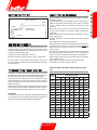
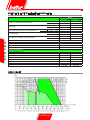
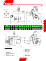
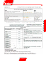
MOD.
MINICOMIST 7 MINICOMIST 11
BURNER OUTPUT
MIN kW 38,5 58,4
MAX kW 66,8 103
FLOW RATE
MIN m³/h 3,9 5,9
MAX m³/h 6,7 10,4
PRESSURE In order to obtain the maximum ow rate
CE MIN mbar 20 20
UNI-CIG MIN mbar 12 20
FLOW RATE
MIN kg/h 3,3 4,9
MAX kg/h 5,7 8,7
BURNER OUTPUT
MIN kW 38,5 58,4
MAX kW 66,8 103
VISCOSITY Light oil 1,5°E a 20°C
VOLTAGE 50Hz Volt 1~ 230V
FAN MOTOR 50Hz kW 0,13 - 2800 r.p.m.
PUMP MOTOR 50Hz kW 0,075 - 2780 r.p.m.
IGNITION TRANSFORMER 50Hz 8 kV - 20 mA
STANDARD ACCESSORIES
BURNER FIXING FLANGE N° 1 N° 1
INSULATING GASKET N° 1 N° 1
INSULATING CORD N° 1 N° 1
FILTER N°1 - 3/8” N°1 - 3/8”
FLEXIBLE PIPE N°2 - 1/4” x 3/8” N°2 - 1/4” x 3/8”
STUD BOLTS N°4 M8 N°4 M8
EXAGONAL NUTS N°4 M8 N°4 M8
FLAT WASHERS N°4 Ø8 N°4 Ø8
WORKING FIELD
TECHNICAL DATA AND OVERALL DIMENSIONS BURNERS

E
N
G
L
I
S
H
8 / 18
0006081159_201102
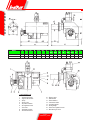
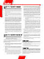
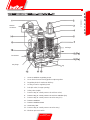
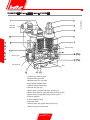
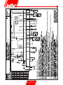
COMPONENTS LIST
1 - Ignition transformer
2 - Light oil electrovalve
3 - Pump
4 - Pump motor
5 - Air pressure switch
6 - Air regulation sector
7 - Fan motor
8 - Gas/light oil switch
9 - Terminal board box
10 - Electric panel
11 - Reset button
12 - Flame detector
13 - Combustion head
14 - Insulating gasket
15 - Sliding ange
16 - Flame disc regulation screw
17 - Monoblock gas valve
0002570110
MOD. A A1 A2 B B1 B2 C D
min
D
max
E
Ø
G
Ø
L
min
L
max
M
Ø
N
MINICOMIST 7 510 300 210 510 205 305 510 40 156 95 3/4” 130 155 M8 115
MINICOMIST 11 510 300 210 510 205 305 510 40 156 95 3/4” 130 155 M8 115

E
N
G
L
I
S
H
9 / 18
0006081159_201102
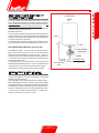
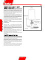
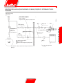
FITTING THE BURNER TO THE BOILER AND
CONNECTING THE GAS PIPE
The burner is tted with a sliding attachment ange on the burner
head. When tting the burner to the boiler, this ange must be
correctly positioned is that the burner head penetrates the boiler by
the amount specied by the manufacturers of the boiler.
When the burner is tted correctly to the boiler, proceed whit the
connection of the gas feed pipe (see
BT 8780 and BT 1387).
The size of the gas feed pipe must be proportional to its length and
to the gas delivery rate in accordance with the UNI standard (see
diagram), and it must be perfectly airtight and properly tested before
running the initial tests on the burner.
It is essential to t a connector to this pipe, near to the burner, for the
easy dismounting of the burner and/or the opening of the boiler door.
FOR BURNERS WITH DUNGS GAS VALVE mod. MB.....
The DUNGS mod. MB.... valve has a lter and gas pressure sta-
biliser, which means that only the cut-off cock and the vibration
damper joint should be tted to the gas feed pipe. A pressure
reduction unit should be installed outside the heating system only
in cases where the gas pressure exceeds the level permitted by
the standard (400 mm.C.A.).
It is recommended to put a bend directly on the burner gas train
before tting the detachable connector. This is to allow the opening
of the boiler door, when the connector itself has been opened.
These details are clearly illustrated in the following diagram.
HYDRAULIC CONNECTIONS (LIGHT OIL)
The connection pipes between tank and burner must be comple-
tely tight. We suggest to use copper or steel pipes of an adequate
diameter (see list and drawing).
At the rigid pipes ands it must be tted the fuel’s detection gates.
Filters, exible pipes and relative connection couplings are supplied
along with burner. Pump is equipped with suitable connecting points
(see drawing) for detection instruments (pressure gauge and vacu-
ummeter). Pressure drop in suction must not exceed 4,6 mm.W.G.
= to 35 cm.Hg. for a proper and silent operation. Probable max.
pressure on suction and on the return 1,5 bar.
UPPER VIEW
BOILER
GATE
DOOR
DOOR OPENING
A DIRECTION
BURNER
MULTIBLOC VALVE
PIPE FITTING
ANTI-VIBRATION
JOINT

E
N
G
L
I
S
H
10 / 18
0006081159_201102
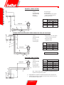
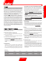
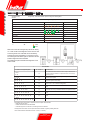
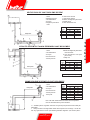
SIPHON FEED SYSTEM WITH FEED FROM THE TOP OF THE TANK
SUCTION FEED SYSTEM
GRAVITY FEED SYSTEM
Dimension P = 3,5 m. (max.)
H - Height difference between minimum fuel tank level and pump axis.
L - Total length of pipeline, including vertical lenght. Subtract 0,25 mt.
for every elbow or gate valve.
N.B. Comply with existing regulations regarding apparatus
required in the pipeline system
1 Tank
2 Feeding pipe
3 Wire-net lter
4 Pump
5 Degasier
6 Suction pipe
7 Return pipe
8 Automatic fuel interception
device at burner shut off
9 Non-return valve
Pump axis
1 Tank
3 Wire-net lter
4 Pump
6 Suction pipe
7 Return pipe
8 Automatic fuel interception
device at burner shut off
9 One-way valve
10 Bottom valve
Pump axis
Pump axis
1 Tank
3 Wire-net lter
4 Pump
6 Suction pipe
7 Return pipe
10 Bottom valve
H Total lenght meters
meters Ø i = 10 mm Øi.= 12 mm
1 20 30
2 25 35
3 30 40
4 35 45
H Total lenght meters
meters Ø i = 10 mm Øi.= 12 mm
1 20 30
2 25 35
3 30 40
4 35 45
H Total lenght meters
meters Ø = 10mm Øi. 12 mm
0,5 15 27
1 12 23
1,5 9 19
2 7 15
2,5 4 10
3 - 7
3,5 - -

E
N
G
L
I
S
H
11 / 18
0006081159_201102
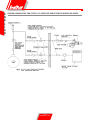
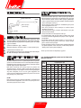
HYDRAULIC DIAGRAM FOR
8502cmt18.tif
Light oil electrovalve
Nozzle
Light oil pump
(12 bar pressure)
Return
Suction
Foot valve
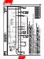
ELECTRICAL CONNECTIONS
Electric lines should be at an adequate distance from
hot parts. Make sure that all electrical connections are
made with ex electric wire, with suitable size for the
voltage and absorbed power.
Maximum current absorbed = 600 VA
Minimum section of the feed line = 1mm
2
with 230V.
For the LGB 22 control box, the intensity of the cell
current should be between 200 microamperes and 500
microamperes.
DUAL FUEL BURNER’S FIRING INDICATION
We suggest to start the burner with the liquid fuel, as in this case
the delivery is bound to the nozzle size whilst the gas delivery can
be easily changed by acting on the relative capacity adjuster.
If the burner is in the automatic version, the selector for the fuel
change connects a cyclic relay which inserts, tanks to an auxiliary
relay, components for the use of both fuels (valves, pressure
switches, pump etc.).
After having changed the position of the selector from gas to light oil
and voiceovers, it occurs to leave it stopped for at least 10 seconds
which is the time the cyclic relay needs to carry out its program.
ATTENTION
If the selector is moved from a position to another before the period
of 10 seconds, the cyclic relay stops in the middle of its program not
allowing to use the burner both with gas and with light oil.
Nozzle
G.P.H.
Pump pressure bar
8 9 10 11 12 13 14
0,60 2,04 2,16 2,28 2,39 2,50 2,60 2,70
0,65 2,21 2,34 2,47 2,59 2,71 2,82 2,92
0,75 2,55 2,70 2,85 2,99 3,12 3,25 3,37
0,85 2,89 3,06 3,23 3,39 3,54 3,68 3,82
1,00 3,40 3,61 3,80 3,99 4,16 4,33 4,50
1,10 3,74 3,97 4,18 4,38 4,58 4,77 4,95
1,20 4,08 4,33 4,56 4,78 5,00 5,20 5,40
1,25 4,25 4,50 4,75 5,00 5,20 5,40 5,60
1,35 4,59 4,87 5,13 5,38 5,62 5,85 6,07
1,50 5,10 5,41 5,70 5,90 6,24 6,50 6,75
1,65 5,61 5,95 6,27 6,58 6,87 7,15 7,42
1,75 5,95 6,31 6,65 6,98 7,29 7,58 7,87
2,00 6,80 7,21 7,60 7,97 8,33 8,67 8,99
2,25 7,65 8,15 8,55 8,97 9,37 9,75 10,12
2,50 8,50 9,01 9,50 9,97 10,41 10,83 11,24
CHECKS PRIOR LIGHT OIL FIRING
Make sure that the nozzle with sprouting angle at 60° is suitable to
the boiler’s capacity.
In the list hereunder you nd the delivery values in kg/h of light oil
related to the nozzle’s size and to the pump’s pressure (normally
12 bar). (Please note that 1 light oil kg corresponds to 10.200
kcal about).
Make sure that the protrusion of the combustion head inside
the combustion chamber is according to boiler manufacturer’s
instructions.
Make sure that the return pipe in tank has no obstructions, such as
gates closed caps etc.
Probable obstructions could cause faults on the pump’s shaft or
ex pipe.
Open slightly the air purge device of the pump.
Disconnect the wire number 39 which feeds the pump motor from
the terminal on the contactor “K1” and connect it from moment the
terminal “K1.56” of the “input junction box” so as to feed directly
the pump motor.
Now close the reverser-switch on the burner and the general one
and make sure that the rotation sense is correct. Thus the pump
motor is connected and starts the pump witch sucks the light oil.
When the light oil ow the air purge device open the main switch
so as to stop the motor.
Be set original connections to the corresponding terminals.
The burner is thus ready to operate at light oil.
TABLE OF NOZZLE DELIVERY RATES IN Kg/h OF LIGHT
OIL

E
N
G
L
I
S
H
12 / 18
0006081159_201102
STARTING UP AND REGULATION WITH LIGHT
OIL
1) Check that the pump and fan motors rotate in the right direction.
2) Make sure that the discharge of combustion products can take
place freely (chimney lock-gates should be open) and that there
is water in the boiler.
3) Open as much as considered necessary, the combustion air
regulator, and open by about half the air passage between
the disk and the head by operating the regulating screw of the
ame disk.
4) Close the main switch and the burner switch in order to connect
the burner and wait for it to start up. The burner is turned on in
this way, and will carry out the pre-ventilation phase. If the air
pressure exceeds the value at which the air pressure switch
has been set, the ignition transformer will be connected and
subsequently the light oil valve will be inserted. With the burner
operating, correct if necessary, the combustion air delivery.
5) The burner is tted with a device which optimises the combustion
by reducing or increasing the air passage between the disk and
the head. Maximum smoke intensity permissible is N° 2 of the
Bacharach scale with a Carbon Dioxide (CO
2
) value between
10 and 13 %. It is normally necessary to reduce the air passage
between the disk and the head when operating with a reduced
fuel delivery. This passage must be proportionately opened
more when the burner is working with a higher fuel delivery.
This manoeuvre can be carried out by operating the regulating
screw of the ame disk. After having modied the ame disk
position, it is then necessary to verify that ignition occurs
correctly.
STARTING UP AND REGULATION WITHMETHANE
GAS
N.B. Please refer to the last pages where specic instructions are
given with regard to regulating the gas delivery in function
with the type of valve tted on the burner.
In order to proceed with ignition, it is indispensable to carry out a
purge of the air contained in the pipeline and check, if the burner is
three-phase, that the sense of rotation of the motor is correct.
Then proceed as follows:
1) Make sure that the discharge of combustion products can take
place freely (chimney lock-gates should be open) and that there
is water in the boiler.
2) Open, as much as considered necessary, the combustion air
regulator, and open by about one third the air passage between
the head and the disk by operating the regulating screw of the
ame disk.
3) Operate the regulators incorporated in the gas valves in such
a way as to obtain the gas delivery presumed necessary.
N.B. Please refer to the last pages where specic instructions
are given with regard to regulating the gas delivery in
function with the type of valve tted on the burner.
4) Give current to the burner by connecting the main switch and
the burner switch. The burner is turned on in this way and will
then carry out the pre-ventilation phase. If the air pressure
exceeds the value at which the air pressure switch has
been set, the ignition transformer will be connected and,
subsequently, the gas valves will be inserted. The safety valve
opens completely while the principle valve, which incorporates
the regulation devices, opens twice. When it opens the rst time,
it realises the starting output immediately. The second time, it
opens gradually and when it is completely open the burner is
operating at the maximum value at which the maximum output
regulator has been set. At rst ignition, successive “shutdowns”
can occur, due to the following reasons:
a) The gas pipeline has not been adequately purged of air
and therefore the quantity of gas is not sufcient to allow
a stable ame.
b) A “shutdown” with flame presence can be caused by
ame instability, due to an incorrect air/gas ratio. This
can be remedied by varying the quantity of air and/or gas
delivered, in order to nd the correct ratio. It could also
be caused by an incorrect distribution of air/gas in the
combustion head. This can be corrected by operating the
regulation device of the combustion head – close more
(by loosening the regulating screw) or open more (by
tightening the regulating screw) the air passage between the
head and the gas diffuser. This can be done by operating
the regulating screw of the ame disk.
5) With the burner on, adapt delivery to the value which
corresponds with the potentiality desired (Methane gas = 8550
kcal/m
3
), by reading the meter. This output can be modied by
operating the special regulator incorporated in the valve, as
explained above.
6) Control that combustion occurs correctly by using the
appropriate instruments. The maximum permissible for Carbon
Monoxide (CO) is 0,1%; with a Carbon Dioxide (CO
2
) value of
between 8 and 10%.
7) After regulation, turn the burner off and on again several times
to check that ignition occurs correctly.
SAFETY CHECKS
After regulation, always check:
1) That the burner stops by “opening” the thermostat and the air
and gas pressure switches;
2) The “shut down” by darkening the photoelectric cell (UV).
To unblock the burner, press the appropriate pushbutton.
MAINTENANCE
At the end of the heating season, it is good practice
to clean the gas and light oil filters, the combustion head
(disk, insulators, and nozzles), the combustion air passages and
the photoelectric cell (UV). It is advisable to use wooden or plastic
instruments to clean the nozzle passages. Nozzles should be re-
placed after 12 months’ use.

E
N
G
L
I
S
H
13 / 18
0006081159_201102
UV CELL
Even the slightest greasiness will compromise the passage of the ul-
traviolet rays through the UV photoelectric cell bulb, thus preventing
the sensitive internal element from receiving the quantity of radiation
necessary for it to function properly. Should the bulb be fouled by
light oil, fuel oil, etc., it is indispensable to clean it thoroughly.
It should be pointed out that even by simply touching the bulb with
the ngers, it is possible to leave a slight greasiness, which could
compromise the working of the UV photoelectric cell.
The UV cell does not “see” daylight or light from an ordinary lamp. It
is possible to verify its sensibility with a ame (or cigarette lighter or
a candle) or with the electric spark that occurs between electrodes
in an ordinary ignition transformer. To ensure that the UV cell works
properly, its current value should be sufciently stable so as not to
fall below the minimum value required for the specic control box.
It may be necessary to search experimentally for the best position
by sliding (axial or rotation movement) the body that contains the
photoelectric cell in respect to the fastening clamp. An inspection
can be carried out by inserting a microammeter, with an adequate
scale, in series to one of the two UV photoelectric cell connection
wires. It is obviously necessary to respect the polarity (+ e -). For
the LGB 22 control box, the cell current should be between 200
microA. and 500 microA.
NOTES ON USE OF PROPANE (L.P.G.)
We think it would be useful to inform you on a few points regarding
use of liquid propane gas (L.P.G.).
1) Approximate evaluation of running costs
a) 1 m
3
of liquid gas in gaseous state has heating power
inferior by about 22.000 Kcal.
b) to obtain 1 m
3
of gas about 2 Kg of liquid gas are required.
This is equal to about 4 litres of liquid gas.
According to the above, it can be deduced that by using liquid gas
(L.P.G.) the following approximate equivalence is obtained:
22.000 kcal = 1 m
3
(in gaseous state) = 2 Kg of L.P.G. (liquid)
= 4 litres L.P.G. (liquid). From this, running costs can be cal-
culated.
2) Safety measures
Liquid gas (L.P.G.) has, in it gaseous state, a specic gravity
superior to that of air (specic gravity of propane gas in relation
to air = 1,56) and therefore does not disperse in air like natural
gas, which has a lower specic gravity (specic gravity of natural
gas in relation to air = 0,60), but precipitates and spreads at
ground level as if it were a liquid. In view of the above principle,
the Ministero dell’Interno ( Home Ofce) has set limitations for
use of Liquid Gas in circular n° 412/4183 of 6 February 1975.
We will look into the points we think most important:
a) Liquid Gas (L.P.G.) for burners and/or boilers can only be
used in rooms above ground and overlooking open spaces.
Installations using liquid gas in basements or cellars are not
permitted.
b) Rooms where liquid gas is used must have ventilation inlets
without closing devices, located on external
walls with a surface of at least 1/15 of the room’s area and a
minimum of 0,5 m
2
. At least one third of the entire surface of
these inlets must be located in the lower part of the external
wall, ush with the oor.
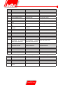
3) Requirements for liquid gas plant to ensure correct opera-
tion and safety
Natural gasication, from cylinder unit or tank, can only be used
for low power plant. Supply capacity at gaseous stage, depen-
ding on tank dimensions and minimum external temperature,
is shown in the following table but only as a rough guide.
4) Burner
The burner must be ordered specically for use with liquid
gas (L.P.G.) so that it is equipped with gas valves of sufcient
dimensions to ensure correct ignition and gradual regulation.
Our valves have dimension is planned for use at a supply
pressure of about
300 mm.W.C. We suggest gas pressure be checked at the
burner by using a water column pressure gauge.
N.B. Maximum and minimum burner pressure (kcal/h) obviously
remains that of the original natural gas burner (L.P.G. has hea-
ting power superior to that of natural gas. Therefore, in order
to burn fully, it requires air quantity in proportion to the thermal
power created).
5) Combustion control
To limit consumption and avoid serious trouble, adjust combu-
stion by using the appropriate instruments.
It is absolutely essential to check that the percentage of carbon
monoxide (CO) does not exceed maximum permitted value of
0,1 % (use a phial analyser or other similar instrument). Please
note that our guarantee does not cover burners operating on
liquid gas (L.P.G.) in plant for which the above measures have
not been taken.
Minimum
temperature - 15 °C - 10 °C - 5 °C - 0 °C + 5 °C
Tank 990 l. 1,6 Kg/h 2,5 Kg/h 3,5 Kg/h 8 Kg/h 10 Kg/h
Tank 3000 l. 2,5 Kg/h 4,5 Kg/h 6,5 Kg/h 9 Kg/h 12 Kg/h
Tank 5000 l. 4 Kg/h 6,5 Kg/h 11,5 Kg/h 16 Kg/h 21 Kg/h

E
N
G
L
I
S
H
14 / 18
0006081159_201102
GENERAL DIAGRAM FOR TWO-STAGE L.P.G. PRESSURE REDUCTION FOR BURNER OR BOILER

E
N
G
L
I
S
H
15 / 18
0006081159_201102
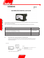
GAS BURNER CONTROL DEVICE GAS LME 22..

E
N
G
L
I
S
H
16 / 18
0006081159_201102
GAS BURNER CONTROL DEVICE GAS LME 22...
Legend …. Steady on p Red
¡ Off l Yellow
n Green
Color code table for multicolor signal lamp (LED)
Status Color code Color
Waiting time «tw», other waiting states
¡....................................... Off
Ignition phase, ignition controlled
l ¡ l ¡ l ¡ l ¡ l
Flashing yellow
Operation, ame o.k.
¡....................................................
Green
Operation, ame not o.k.
n ¡ n ¡ n ¡ n ¡ n
Flashing green
Extraneous light on burner startup
n p n p n p n p n
Green-red
Undervoltage
l p l p l p l p l Yellow-red
Fault, alarm
p.....................................................
Red
Error code output (refer to «Error code table»)
p ¡ p ¡ p ¡ p ¡
Flashing red
Interface diagnostics
p p p p p p p p
Red icker light
Operational status During startup, status indication takes place according to the following table:
indication
Error code table
Red blink code of signal lamp (LED) «AL» at term. 10 Possible cause
2 blinks
l l
On
No establishment of ame at the end of «TSA» -Faulty or soiled fuel valves
-Faulty or soiled ame detector -Poor adjustment of burner, no fuel -Faulty
ignition equipment
3 x blinks
l l l
On
«LP» faulty -No or faulty air pressure signal after completion «t10» - «LP» is
welded in normal position
4 blinks
l l l l
On
Extraneous light when burner startup
5 blinks
l l l l l
On Time out «LP» - «LP» is welded in working position
6 blinks
l l l l l l
On Free
7 blinks
l l l l l l l
On
Too many losses of ame during operation (limitation of repetitions) -Faulty or
soiled fuel valves -Faulty or soiled ame detector -Poor adjustment of burner
8 x blinks
l l l l l l l l
On Free
9 blinks
l l l l l l l l l
On Free
10 blinks
l l l l l l l l l l
Off Wiring error or internal error, output contacts, other faults
During the time the cause of fault is diagnosed, the control outputs are deactivated
- Burner remains shut down
- External fault indication remains deactivated
- Fault status signal «AL» at terminal 10, according to the error code table
The diagnostics of the cause of fault is quit and the burner switched on again by resetting the burner
control. Press thelockout reset button for about 1 second (< 3 seconds).
After lockout. the red fault signa llamp will remaln steady
on. In thal conditio visual diagnostics of the cause of fault
acccording to the error code table can be activated by
presslng the lockout reset button for more than 3 secon-
ds. Pressing the reset button again for at least 3 seconds,
interface diagnostics will be activated
The followlng sequence activates the diagnostics of Ihe
cause of fault:

E
N
G
L
I
S
H
17 / 18
0006081159_201102
N° 0002910301
COMBINED DUNGS GAS VALVE (MONOBLOC) MOD. MB-DLE ... B01
1 - Acces to stabilizer regulating screw
2 - Acces knob for manoeuvring ignition output regulator
3 - Regulating knob for maximum delivery
4 - Locking screw for regulating knob
5 - Principle valve (2-stage opening)
6 - Safety valve (rapid)
7 - Pressure tap (to control pressure in exit from valve)
8 - Pressure tap (to control pressure in exit from stabilizer (Pa)
9 - Pressure tap (to control pressure at valve entry (Pe)
10 - Pressure stabilizer
11 - Pressure stabilizer bleed
12 - Small entry lter
13 - Pressure tap (to control pressure at valve entry)
14 - Minimum pressure switch
ow direction
electrical
connections
entry ange
exit ange
plug

E
N
G
L
I
S
H
18 / 18
0006081159_201102
The gas valve unit DUNGS MB - DLE... is made up of:
1) A safety valve which closes opens rapidly.
2) A principle valve which opens in two stage (5). The rst opening
stage occurs rapidly (release) and is adjustable by unscrewing
the knob (2) and inserting the back part of the regulating pin
underneath. The + and symbol can be seen on the head of the
valve and these indicate the direction in which the pin should be
turned in order to increase or the ignition output (the rst stage of
the valve opening). By rotating in a clockwise direction, the initial
delivery (ignition ame) can be reduced; in an anti-clockwise
direction, the initial delivery is increased. The complete run from
zero to maximum, and viceversa, is slightly more than three
turns (40% of the total opening). When the rst opening stage
has taken place, the valve comtinues to open slowly and takes
15 seconds to reach the maximumopen position. To regulate
maximum delivery desired, loosen the locking screw (4) (the one
with the protruding head and not the one locked and sealed with
paint) and turn knob (3). Rotate in a clockwise direction to reduce
delivery and in anti-clockwise direction to increase it.
It should be pointed out that when the regulating knob is turned, the
end - of - the - run which limits the operating of the valve moves;
therefore, when the knob has been turned untilit reaches the - sign,
the valve will not open and the burner will not ignite. To get ignition,
it’s necessary to turn the knob in an anti-clockwise direction towards
the + sign. The complete run from zero to maximum and viceversa is
neary six turns of the knob. This regulating operation (for maximum
and ignition output) must be carried out without forcing against the
end - of - the - run - positions.
3) The pressure stabilizer (10) can be regulated (see table) by
manoeuvring the screw which can be reached by sliding the
cover (1) to one side. The complete run from the maximum to
the position and viceversais about 80 turns. Do not force against
the end - of - the - run positions. Around the screw are arrows
with symbols which indicate the sense of rotation: to increase
pressure, rotate in a clockwise direction, to reduce it, rotate in
an anti-clockwise direction. This stabilizer hermetically closes
“upstream” and “downstream” when there is no ow of gas.
Dfferent springs to obtain different pressure value from those
described above are not foreseen.
To regulate the pressure stabilizer, connect a water mano-
meter to the rubber tube holder installed on the tap (8) in
correspondence with the exit of the stabilizer.
4) The small entry lter (12) can be reached for cleaning by removing
one of the two side closing plates.
5) The minimum pressure switch (14) and the maximum pressure
switch (15). To regulate it remove the transparent cover and
operate the black knob. The reference mark is the small rec-
tangle to be found on the yellow disk which the regulating knob
rotates around.
6) At entry, a tap (13) has been tted to the connction ange to
measure the entry pressure. At the exit of the connection ange,
there is also a tap (7) to measure the pressure in exit.
VALVE INLET MAX PRESSURE ADJUSTTABLE OUTLET PRESSURE TYPE OF GAS
MODEL (PE) mbar FROM THE STABILIZER (PA) mbar
MB ...B01 S 20 200 from 4 to 20 Natural Gas / L.P.G.
7) The side pressure taps (9), indicated as Pe, are in communication
with the entry pressure.
8) The side pressure taps (8) indicated as Pa, are used to measure
the pressure coming out of the stabilizer. It might be useful to
know, that the pressure coming out of the valve unit (to be
measured at tap 7), corrisponds to the pressure regulated by
the stabilizer and is reduced in order to overcome the crossing
resistance of the principle valve (5). It should be pointed out,
that the valve crossing resistances depend on the opening of the
valve regulated by knob 3 through wjich the end - of - the - run
position is adjusted. To regulate the pressure stabilizer, conn-
ct a water manometer to the rubben tube holder installed on
tap (8) in correspondence to the stabilizer exit (Pa).
9) The holes of the pressure stabilizer bleed (11) should be free and
unblocked if it’s to function properly.
SUGGESTIONS FOR REGULATING THE GAS VALVE
1) Connect a water manometer to the pressure tap Pa (indicated
as n° 8) to measure the pressure coming out of he stabili-
zer.
2) Put the gas delivery regulators for ignition (2) and for maximum
delivery (3) in the positions presumed necessary for the delivery
desired. Also open adequately the combustion air regulator.
3) Turn on the burner.
4) With the burner on, manoeuvre the regulating screw (1) of the
stabilizer regulator of the gas pressure and regulator of the gas
pressure and regulate the pressure at the value considered ne-
cessary to obtain the output desired, when the maximum output
regulator (3) is in the maximum opening position. It should be
pointed out that, normally, the above conditions require about
40 ÷ 70 mm.W.C.
5) Put the ignition output regulator (2) in the position considered
necessary to obtain ignition with the minimum delivery possible.

T
ü
r
k
ç
e
1 / 15
0006081159_201102
BALTUR S.p.A.
Via Ferrarese 10 - 44042 CENTO (Ferrara) ITALIA
Tel. 051.684.37.11 Fax 051.685.75.27/28
(International Tel. ++39.051.684.37.11 - Fax ++39.051.683.06.86)
http://www.baltur.it - http://www.baltur.com - E-MAIL info@baltur.it
04/01/2010
Uygunluk Beyanı
Aşağıdaki ürünlerimizin
BPM...; BGN…; BT…; BTG…; BTL…; TBML...; Comist…;
GI…; GI…Mist; Minicomist…; PYR…; RiNOx…; Spark...;
Sparkgas...; TBG...;TBL...; TBML ...; TS…; IBR...; IB...;
(Varyant: … LX, düşük NOx emisyonları için)
Konut ve sanayi kullanımı için hava üemeli sıvı, gaz ve karma yakıtlı brülörler
aşağıdaki Avrupa Direktierinin minimum şartlarını karşılamaktadır:
90/396/CEE ...............................................(D.A.G.)
89/336/CEE - 2004/108/CE ........................(C.E.M.)
73/23/CEE – 2006/95/CE ...........................(D.B.T.)
2006/42/CEE .............................................(D.M.)
ve aşağıdaki Avrupa Standartlarına uygundur:
UNI EN 676:2008 (gaz ve kombinasyonu, gaz tarafı)
UNI EN 267:2002 (dizel ve kombinasyonu, dizel tarafı)
Bu ürünler bu nedenle aşağıdaki işaretle işaretlenmiştir:
0085
Dr. Riccardo Fava
Genel Müdür / CEO
!
Uyarı / not
i
Bilgiler
I
Tehlike / Dikkat
Indice analitico
BRÜLÖRLERİN TEKNİK ÖZELLİKLERİ VE TAM BOYUTLARI ...................................................................................................4
BRÜLÖRÜN KAZANA BAĞLANMASI VE GAZ HATTININ BAĞLANMASI .................................................................................6
ÇİFT YAKITLI BRÜLÖRÜ DEVREYE ALMAK İÇİN TALİMAT - ’E AİT HİDROLİK ŞEMASI - ELEKTRİK BAĞLANTILARI ..........8
BAKIM - DOĞAL GAZ İLE İLK ÇALIŞTIRMA VE YANMA AYARI - MOTORİN İLE İLK ÇALIŞTIRMA VE YANMA AYARI .............9
DUNGS MB-DLE-B01 model BİLEŞİK (monoblok) GAZ VALFI ...................................................................................................14
GAZ BRÜLÖRÜ KONTROL KUTULARI .......................................................................................................................................12
PROPAN (L.P.G.) KULLANIMINA AİT NOTLAR ...........................................................................................................................10

T
ü
r
k
ç
e
2 / 15
0006081159_201102
ÖNSÖZ
Bu uyarı notları sivil kullanım ve sıcak su üretimi için ısıtma sistemleri
bileşenlerinin sağlıklı kullanımını sağlamak amacı ile hazırlanmıştır. Bu
notlar, yeterli güvenirliliğe sahip donanımların, doğru olmayan ve hatalı
kurulumlar veya uygunsuz ve mantıksız kullanımlar sebebi ile zarara yol
açmasının önlenmesi amacı ile nasıl hareket edileceğini göstermektedir.
İlave olarak bu kılavuzdaki uyarı notları son kullanıcıların anlayabileceği bir
dilde teknik olarak hazırlanmış olup, emniyetle ilgili hususlardan kullanıcıların
bilgi sahibi olmasını hede er. Üretici, kurulum veya kullanım sırasında üretici
talimatlarına uyma konusundaki aksaklıklardan kaynaklanan hataların
sebep olduğu hasarlardan kontratlı olsun veya ekstra kontratlı olsun
sorumlu değildir.
GENEL UYARI NOTLARI
• Kullanım kılavuzu ürünün özel ve gereki parçasıdır ve mutlaka kullanıcıya
verilmesi gerekmektedir. Emniyetli kullanım, bakım ve kurulumla ilgili
önemli bilgiler içerdiğinden kılavuzdaki uyarıları dikkatlice okuyunuz.
Kılavuzu ihtiyacınız olduğunda bulabileceğiniz yerde muhafaza
ediniz.
• Malzemeler, geçerli standartlara ve üretici talimatına göre kali ye
teknisyenler tarafından kurulmalıdır. “Kali ye Teknikerler” demekle,
domestik ısıtma ve sıcak su üretimi sistem parçaları hakkında uzman
ve özellikle üretici tarafından yetkilendirilmiş kişiler kastedismektedir.
Hatalı kurulum insanlara, hayvanlara ve eşyalara zarar verebilir. Bu tür
zararlardan üretici sorumlu değildir.
• Ambalaj açıldığında bütün parçaların mevcut olduğunu ve hasarsız
olduğunu kontrol ediniz. Şüphede iseniz, malzemeler kullanmayın ve
satıcınıza geri gönderiniz. Ambalajlama malzemelerini ( tahta kafesli
sandık, plastik poşetler, köpükler, vb... ) çocukların ulaşabilecekleri
yerden uzak tutunuz. Bu malzemeler toplanarak, çevre kirliliği
oluşturmamaları için uygun bir yere atılmaları gerekir.
• Her hangi bir bakım veya temizleme işleminden önce ana elektrik
beslemesindeki sistem şalterini kullanarak cihazınızın elektriğini kesin
veya ilgili bütün cihazların elektriğini keserek kapatın.
• Eğer sistemde hata varsa veya cihazınız düzgün çalışmıyorsa, cihazınızı
kapatın, tamir etmeye çalışmayın veya malzemeye müdahale etmeyin.
Böyle durumlarda sadece yetkili servis ile irtibata geçiniz. Her hangi
bir malzeme tamiri orijinal yedek malzemeler kullanılarak Baltur yetkili
servisleri tarafından yapılmalıdır. Yukarıdaki durumlardaki hatalı
eylemler malzemenin güvenirliliğini tehlikeye atacaktır. Donanımın
doğru ve verimli çalışmasını sağlamak için yetkili servisler tarafından
kullanma talimatlarına uygun şekilde periyodik bakımlarının yapılması
gerekmektedir.
• Donanımlar başka bir kullanıcıya satılır veya gönderilirse veya sahibi
cihazı bırakır veya taşır ise; kullanma kılavuzlarının da daima cihazın
yanında olmasını sağlayınız. Böylece yeni sahibi ve/veya monte eden
kişi kılavuzdan yararlanabilir.
• Opsiyonel malzemeler veya (elektrik malzemesi dahil) kitler de dahil
olmak üzere cihazın bütün donanımı için sadece orijinal malzemeler
kullanılmalıdır.
BRÜLÖRLER
• Bu cihaz, sadece kazanlarda, sıcak su kazanları, fırınlar veya diğer
benzeri donanımlara bağlanarak ve atmosferik ajanlara (yağmur, toz gibi)
maruz kalmayan uygulamalar için kullanılmalıdır.Başka diğer kullanım
şekilleri uygun olmayan kullanımdır ve dolayısıyla tehlikelidir.
• Brülör, yürürlülükteki düzenlemelere göre ve her durumda düzgün
yanmanın sağlanabileceği yeterlilikte havalandırmanın olduğu uygun
mahallere kurulmalıdır.
• Tehlikeli toksit karışımlar ve patlayıcı gaz formları oluşabileceğinden,
brülörün veya kazanın kurulduğu kazan dairesinin havalandırma
açıklığının ve brülör hava emiş ızgarası açıklığının ebadını azaltmayın
ve kapatmayın.
• Brülörü bağlamadan önce, sistem beslemesi (elektrik, gaz, motorin, veya
başka yakıt) ile alakalı bilgileri üzerindeki etiketinden kontrol ediniz.
• Brülörün sıcak parçalarına dokunmayınız. Genelde aleve yakın
alanlardaki ve yakıt ön ısıtma sistemindeki bu parçalar, cihazın çalışması
esnasında ısınırlar ve brülör durduğunda da bir süre sıcak kalırlar.
• Brülör artık kullanılmayacak ise yetkili teknikerler tarafından aşağıdaki
işlemler kesinlikle yapılmalıdır;
a) Ana şalterden elektrik besleme kablosu sökülerek, elektrik beslemesinin
kesilmesi,
b) Yakıt beslemesini, kapama valfını kullanarak kapatılması ve valfın
açma kolunun sökülmesi,
c) Potansiyel tehlike oluşturabilecek parçaların emniyete alınması,
Özel uyarı notları
• Alev yanma odasında oluşacak şekilde brülörün ısı üretecine bağlantısının
emniyetle yapıldığını kontrol edin.
• Brülörü devreye almadan önce ve en az yılda bir yetkili teknikerler
tarafından test edilmesi gereken işlemler aşağıda bildirilmiştir;
a) Brülörün yakıt debisi ayarını, ısı jeneratörünün kapasitesine göre
ayarlanması.
b) En azından yürürlükteki düzenlemeler ile bildirilen minimum hava ayarı
değerinde brülörün yanma verimliliğini sağlamak amacıyla yanma havası
debisinin ayarlanması.
c) Hava kirliliğine yol açan NOx ve yanmamış gazların yürürlükteki
mevzuata göre müsaade edilen sınır değerlerini aşmadığının kontrolunun
yapılması.
d) Emniyet cihazlarının ve ayar cihazlarının düzgün çalıştığının kontrolünün
yapılması.
e) Yanma ürünleri tahliye edildiği kanalın durumunun kontrol edilmesi.
f) Ayar işlemleri yapıldıktan sonra ayar cihazlarının mekanik emniyet
kilitlemelerinin yapılması,
g) Brülör kullanma ve bakım kılavuzunun kazan dairesinde olduğunun
kontrolünün yapılması.
• Eğer brülör devamlı olarak arızaya geçip duruyorsa, her defasında
resetleme yapmayı denemeyiniz.En yakın yetkili servisi problemi çözmesiiçin
çağırınız.
• Yürürlükteki düzenlemelere göre ekipmanların çalıştırılması ve bakımının
sadece yetkili servisler tarafından yapılmalıdır.
I
BRÜLÖRÜN GÜVENLE KULLANILMASI İÇİN KULLANICIYA UYARI NOTLARI
Sayfa yükleniyor...
Sayfa yükleniyor...
Sayfa yükleniyor...
Sayfa yükleniyor...
Sayfa yükleniyor...
Sayfa yükleniyor...
Sayfa yükleniyor...
Sayfa yükleniyor...
Sayfa yükleniyor...
Sayfa yükleniyor...
Sayfa yükleniyor...
Sayfa yükleniyor...
Sayfa yükleniyor...
Sayfa yükleniyor...
Sayfa yükleniyor...
Sayfa yükleniyor...
Sayfa yükleniyor...
Sayfa yükleniyor...
-
 1
1
-
 2
2
-
 3
3
-
 4
4
-
 5
5
-
 6
6
-
 7
7
-
 8
8
-
 9
9
-
 10
10
-
 11
11
-
 12
12
-
 13
13
-
 14
14
-
 15
15
-
 16
16
-
 17
17
-
 18
18
-
 19
19
-
 20
20
-
 21
21
-
 22
22
-
 23
23
-
 24
24
-
 25
25
-
 26
26
-
 27
27
-
 28
28
-
 29
29
-
 30
30
-
 31
31
-
 32
32
-
 33
33
-
 34
34
-
 35
35
-
 36
36
-
 37
37
-
 38
38


BALTUR Minicomist 11 Kullanım kılavuzu
- Tip
- Kullanım kılavuzu
- Bu kılavuz aynı zamanda aşağıdakiler için de uygundur:
diğer dillerde
- English: BALTUR Minicomist 11 User manual
İlgili makaleler
-
BALTUR TBML 1200 ME Use and Maintenance Manual
-
-
-
-
-
-
-
-
-
Diğer belgeler
-
Ferroli PEGASUS D 30 K 100 LN Instructions For Use, Installation And Maintenance
-
Hoover HMM6724SHX Kullanım kılavuzu
-
 Unical !DEA Kullanım kılavuzu
-
Master B 35 B 70 B 100 B 150 CED El kitabı
-
 Unical KONm Kullanım kılavuzu
-
-
 Unical KONe Kullanım kılavuzu
-
Whirlpool HBG L20 B El kitabı
-
IKEA HBT S20 S Kullanici rehberi
-


