
185.7320.59/R.AA/24.09.2021
Montaj Talimatları
Installation Manual
TR / EN

2
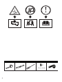
Ø 3,5 x 22 mm
x2

3
20
446
257 265
546
53
505
min: 735
max: 1025
*
598 - 60 cm
898 - 90 cm
*
min.650 min.650
1
2

4
650*
25
302,4
91,191,1
100100
261,6
599
650*
25
302,4
411
25
min: 910
max: 1138
91,191,1
91,191,1
100100
3a 3b
650*
1
599
650*
min: 735
max: 1025
650*
5
4a 4b

5
411
91,191,1
91,191,1
2
3
25
650*
6
7

6
9
10
8

7
1 2
3
11
R 150 mm R 120 mm
12
13

8
1
2
14
15

9
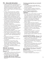
TR - Güvenlik talimatları
•Garantinin geçerliliğini kaybetmemesi için,
ürünün yetkili bir kişi tarafından geçerli
yönetmeliklere göre kurulması gerekir. Yetkili
olmayan kişiler tarafından yapılan işlemler
nedeniyle doğabilecek zararlardan üretici
firma sorumlu tutulamaz ve ürünün garantisi
geçersiz olur.
•Ürünün yerleştirileceği yerin ve elektrik
tesisatının hazırlanması müşteriye aittir.
Yetkili Servisi çağırmadan önce, elektrik
tesisatının uygun olduğundan emin olun.
Değilse ehliyetli bir elektrikçi ve tesisatçı
çağırarak gerekli düzenlemeleri yaptırın.
•Ürünün kurulumunda, elektrikle ilgili yerel
standartlarda belirtilen kurallara uyulmalıdır.
•Ürünün kurulumundan önce içerisindeki
tüm malzeme ve dökümanları çıkarın ve
ürün üzerinde herhangi bir hasar olup
olmadığını kontrol edin. Ürün hasarlıysa
kurulumunu yaptırmayın.
•Ürün ağırdır, ürünü en az iki kişiyle taşıyın.
•Kurulum öncesi montaj yapılacak alanda
bulunan elektrik bağlantılarını kesin.
•Vida veya sabitleyici ekipmanın montajının
talimatlar doğrultusunda yapılmaması
elektrik tehlikesi doğurabilir.
•Ürün parçalarında keskin yüzeyler olabilir.
Kurulum için koruyucu eldiven kullanın.
•Ürün yeterince sabitlenmemiş ise düşme
riski oluşabilir. Tüm sabitleme parçalarının
güvenli bir şekilde sabitlendiğinden emin
olun.
•Davlumbazın genişliği en az ocağınızın
genişliğine eşit olmalıdır.
•Kurulum şemalarında verilen ölçüler mm
cinsindendir.
•Davlumbaz ile dışarı atılacak hava,
gaz veya başka yakıtlar yakan diğer
cihazlar tarafından kullanılan bir bacaya
verilmemelidir. (Sadece havayı odaya geri
veren cihazlar için geçerli değildir)
•Havanın dışarı atılmasıyla ilgili mevzuata
uyulmalıdır.
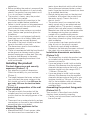
Ürünün kurulumu
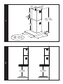
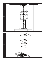
Ürün boyutları ve güvenlik ölçüleri
(Resim 1-2)
•Ürün boyutlarına dikkat edin. Mobilyanıza
uygunluğunu kontrol edin. (Resim 1)
•Davlumbazınızın alt yüzeyi ile ocağın
üst yüzeyi arasındaki yükseklik, gazlı
ocaklarda 650 mm‘den, elektrikli
ocaklarda 650 mm’den az olmamalıdır.
(Resim 2)
Kurulum yapılacak duvarın kontrolü
ve hazırlığı
•Ürünün kurulumunun yapılacağı duvar
ürünü taşıma gücüne sahip, dik ve düz bir
konumda olmalıdır.
•Kurulum yapılacak duvarın üzerinde ve
açılacak deliklerin etrafında su, elektrik ve
gaz bağlantıları bulunmamalıdır.
Ürünün elektrik bağlantısının
yapılması
•Bu cihaz iki izli besleme kablosu ile üretilmiş
olup, ana şebekeye çift kutuplu kontak
uçları arasında en az 3 mm boşluk bulunan
bir elektrik anahtarı ile bağlanmalıdır. Elektrik
bağlantısını ehliyetli bir elektrikçiye yaptırın.
•Elektrik tesisatı üzerinde herhangi bir
çalışmaya başlamadan önce ürünün
elektrik bağlantısını kesin.Elektrik çarpması
tehlikesi vardır.
•Ürünün şebeke elektriğine bağlantısı
yalnızca yetkili ve ehliyetli bir kişi tarafından
yapılabilir.Yetkili olmayan kişiler tarafından
yapılan işlemler nedeniyle doğabilecek
zararlardan üretici firma sorumlu tutulamaz.
•Ürününüzü, kurulum sonrası elektrik
bağlantısına (priz, fiş) kolayca ulaşılabilir
şekilde monte edin.
•Ürününüz fişli ise kurulum sırasında fişi
keserek elektrik bağlantısı yapmayın.
Kesilerek yapılan bağlantılarda ürün
garantisi geçersiz olur ve kullanıcı güvenliği
açısından tehlike oluşturur.
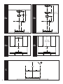
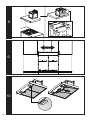
Kurulum ölçü ve detayları (Resim 3-4)
•Ürünün çift baca ile kurulum yapılabileceği
ölçüler resim 3b de gösterilmiştir.
•Çift baca ile monte edecekseniz ocak üzeri
gerekli boşluk mesafesiden mobilyanıza
kadar olan ölçü 910-1138 mm aralığında
olmalıdır. (Resim 4b)
•Tek baca ile monte edecekseniz, ocak üzeri
gerekli boşluk mesafesiden mobilyanıza
kadar olan ölçü 748 mm olmalıdır.
(Resim 3a-4a) Tek baca montaj için
havalandırma deliği olan üst bacayı kullanın.
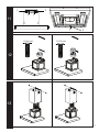
Ürün sabitleme parçalarının montajı
(Resim 5-6-7)
Ürününüz çift baca sacı montaj örneklemesi
üzerinden anlatılmaktadır.
•Ocağınızı ortalayarak duvara dikey bir

10
eksen çizgisi çizin.
•Ocağınızın üst noktasından 650 mm
ölçerek yatay bir referans çizgisi çizin.
(Resim 5)
•Çizdiğiniz referans noktasına ürünle verilen
şablonu ortalayarak duvara yapıştırın
ve şablonda bulunan delikleri kalem ile
işaretleyin. (Resim 6)
•Mobilyanızın yada tavanınızın üst kısmından
resim 6’da verilen ölçülere göre baca
sabitleme parçaları için delikleri işaretleyin.
•Davlumbaz sabitleme parçasını ve baca
sabitleme parçalarını resim 7’de belirtildiği
gibi duvara sabitleyin.
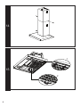
Davlumbazın yerine asılması,
hizalanması ve sabitlenmesi (Resim
8-9-10-11)
•Davlumbazınızı duvara sabitlediğiniz
davlumbaz sabitmeleme parçasına asın.
(Resim 8)
•Davlumbazını sabitleme parçası üzerinde
sağa sola kaydırarak ocağınızı ortalayarak
şekilde hizalayın. (Resim 9)
•Resim 10’da gösterildiği gibi alüminyum
filtreleri çıkarın.
•Davlumbazınızı resim 11’de gösterildiği gibi
davlumbaz sabitleme parçasına ve duavara
sabitleyin.
•Alüminyum filtreleri yerine takın.
Baca çıkış borusunun takılması
(Resim 12)
•Resim 12’de gösterildiği gibi baca çıkışına,
ters hava akışını engelleyen kapağı
yerleştirin.
•Baca çıkış borunuzun çapı 150 mm ise,
baca çıkış borusunu kapağın üzerine
yerleştirin.
•Baca çıkış borunuzun çapı 120 mm ise;
kapağın üzerine baca bağlantı adaptörünü
yerleştirdikten sonra baca çıkış borusunu
yerleştirin.
•Bağlantı yerlerini uygun bir şekilde izole
edin.
Baca saclarının sabitlenmesi (Resim
13-14)
•Baca çıkış borunuzun çapı 120 mm ise;
baca bağlantı adaptörü ile ürün hava çıkış
yuvasının birleşimi etrafına ürünle birlikte
verilen bantı yapıştırın.(Resim13)
•Üst baca sacını, üst baca sabitleme
parçasına yanlarda bulunan yuvarlarından 2
adet vida ile sabitleyin. (Resim 13)
•Alt baca sacını, alt baca sabitleme
parçasına yanlarda bulunan yuvarlarından 2
adet vida ile sabitleyin. (Resim 14)
•Alt baca sacını davlumbaz üzerinde bulunan
alt delik yuvarlarından 2 vida ile sabitleyerek
kurulumu tamamlayın. (Resim 14)
Karbon filtreli kurulum (Resim 15)
•Karbon filtreli kurulumda ortamdan
emilen hava; alüminyum filtreden geçip
kokulardan arındırılır. Karbon filtrelerden ve
hava yönlendiricisinden geçtikten sonra
bacanın yan yüzeyi üzerindeki havalandırma
ızgaralarından ortama geri verilir. Karbon
filtreli kullanımda baca çıkış boruları
kullanılmamaktadır.
•Karbon filtreyi takmak için alüminyum
filtreleri çıkarın. Önce karbon filtrelenin
üzerinde bulunan tırnakları resim 15’de
görüldüğü gibi yuvalarına yerleştirin (1).
Sonra karbon filtrenin diğer ucunda
bulunan kilitleri yukarı bastırarak takın (2).
•Alüminyum filtreleri yerine takıp, Resim
14’de gösterildiği gibi baca saclarını
sabitleyin.
•Alüminyum filtrelerinin düzenli temizliği
ve bakımı yapılmadığında ve karbon
filtrenin ömrü dolduğunda (yaklaşık 4 ay)
değiştirilmediği takdirde yangına neden
olma ihtimalleri bulunmaktadır.
Son kontrol
•Davlumbazınızı ve lambasını kullanma
kılavuzda anlatıldığı gibi çalıştırarak
kontrolünü yapın.
EN - Safety instruction
•Product must be installed by a qualified
person in accordance with the regulations
in force. The manufacturer shall not be
held responsible for damages arising from
procedures carried out by unauthorized
persons which may also void the warranty.
•Preparation of location and electrical
installation for the product is under
customer’s responsibility. Before calling
the Authorized Service, make sure that the
electrical installation is suitable. If not, call a
qualified electrician to make the necessary
arrangements.
•The product must be installed in
accordance with all local electrical

11
regulations.
•Before installing the product, remove all the
materials and documents in it and visually
check if the product has any defects on it.
If so, do not have it installed.
•The product is heavy, carry the product
with at least two people
•Disconnect electrical connections in the
area to be installed before installation.
•Failure to install screws or fixing equipment
in accordance with the instructions may
result in electrical hazard.
•There may be sharp surfaces on product
parts. Always wear protective gloves for
installation.
•If the product is not fastened sufficiently,
there may be a risk of falling. Make sure
that all fixings are securely fastened.
•The width of the hood should be at least
equal to the width of your hob.
•The dimensions given in the installation
diagrams are in mm.
•The air to be exhausted with the hood should
not be given to a chimney used by other
devices burning gas or other fuels. (Not only
for devices that return air to the room)
•Regulations regarding the exhaust of air
must be followed.
Installing the product
Product dimensions and security
measures (Picture 1-2)
•Pay attention to product dimensions.
Check the suitability for your furniture.
(Picture 1)
•The height between the lower surface of
your hood and the upper surface of the
hob should not be less than 650 mm for
gas hobs, 650 mm for electrical hobs.
(Picture 2)
Control and preparation of the wall
to be installed
•The wall on which the product will be
installed must be in an upright and flat
position that has the carrying power of the
product.
•There must be no water, electricity and gas
connections on the wall to be installed and
around the holes to be drilled.
Connecting the appliance to the
electricity supply
•Manufactured with 2-track power cable,
this device must be connected to the
mains by an electrical switch with at least
3mm clearance between bipolar contact
leads. Have the electrical connections done
by a qualified electrician.
•Before starting any work on the electrical
installation, disconnect the product from
the mains supply. There is the risk of
electric shock!
•The product must be connected to the
mains supply only by an authorised and
qualified person. The product’s warranty
period starts only after correct installation.
Manufacturer shall not be held responsible
for damages arising from procedures
carried out by unauthorised persons.
•Install your appliance so that you can reach
the power connection (plug, outlet) easily
after installation.
•If your product has been produced with
plug, do not cut the plug to connect
to electrical supply during installation.
Otherwise, the warranty becomes void and
the safety risks may happen for users.
Installation dimensions and details
(Picture 3-4))
•The dimensions in which the product can
be installed with a double chimney are
shown in picture 3b.
•If you are going to install it with a double
chimney, the measure from the required
clearance distance above the hob to your
furniture should be in the range of 910-
1138 mm. (Picture 4b)
•If you are going to install it with a single
chimney, the measure from the required
clearance distance above the hob to your
furniture should be 748 mm. (Picture 3a-
4a) For the installation with one chimney,
use the upper chimney which has
ventilation hole.
Assembling the product fixing parts
(Picture 5-6-7)
Your product is described over double
chimney sheet assembly sampling.
•Center your hob and draw a vertical axis
line on the wall.

12
•Draw a horizontal reference line measuring
650 mm from the top of your hob. (Picture 5)
•Center the template given with the product
on the reference point you have drawn,
paste it on the wall and mark the holes in
the template with a pencil. (Picture 6)
•Mark the holes for the chimney fixing
parts according to the dimensions given in
picture 6 from the top of your furniture or
ceiling.
•Fix the hood fixing part and chimney fixing
parts to the wall as shown in picture 7.
Hanging, aligning and fixing the hood
(Picture 8-9-10-11)
•Hang your hood on the hood fixing part
that you have fixed to the wall. (Picture 8)
•Align your hob in a central position by
sliding the hood left and right on the fixing
parts. (Picture 9)
•Remove the aluminum filters as shown in
picture 10.
•Fix your hood on the hood fixing and wall
part as shown in picture 11.
•Fit the aluminum filters into its place.
•Fitting the chimney outlet pipe
(Picture 12)
•As shown in the picture 12, place the
cover that prevents reversed air flow to the
chimney outlet.
•If your chimney connection pipe’s diameter
is 150 mm place the chimney outlet pipe
onto the cover
•If your chimney connection pipe’s diameter
is 120 mm; Place the chimney outlet pipe
after placing the connection adapter on the
cover.
•Properly insulate the connection points.
Fixing the chimney sheets (Picture
13-14)
•If your chimney connection pipe’s diameter
is 120 mm; Stick the supplied tape around
the junction of the connection adapter and
the air outlet slot. (Picture 13)
•Fix the upper chimney sheet to the upper
chimney fixing part with 2 screws from the
sides of the curves. (Picture 13)
•Fix the lower chimney sheet to the lower
chimney fixing part with 2 screws from the
curves on the sides. (Picture 14)
•Complete the installation by fixing the lower
chimney sheet with 2 screws from the
bottom hole circles on the hood. (Picture
14)
Carbon filter installation (Picture 15)
•In the carbon filter installation, the air
sucked from the environment; It passes
through the aluminum filter and is purified
from odors. After passing through the
carbon filters and the air diverter, it is
given back to the environment through
the ventilation grilles on the side surface of
the chimney. Chimney outlet pipes are not
used in carbon filter use.
•Remove the aluminum filters to install the
carbon filter. First, place the tabs on the
carbon filter into their sockets as seen in
picture 15 (1). Then, press the locks on the
other end of the carbon filter upwards (2).
•Replace the aluminum filters and fix the flue
plates as shown in Picture 14.
•If the aluminum filters are not cleaned
and maintained regularly and the carbon
filter is not replaced when its life is over
(approximately 4 months), there is a
possibility of fire.
Final check
•Control your hood and lamp by operating it
as described in the user manual.
-
 1
1
-
 2
2
-
 3
3
-
 4
4
-
 5
5
-
 6
6
-
 7
7
-
 8
8
-
 9
9
-
 10
10
-
 11
11
-
 12
12


Beko BDT 6062 B Kullanım kılavuzu
- Tip
- Kullanım kılavuzu
- Bu kılavuz aynı zamanda aşağıdakiler için de uygundur:
diğer dillerde
- English: Beko BDT 6062 B User manual
Diğer belgeler
-
Samsung NK24N7060VB Kullanım kılavuzu
-
-
Franke FTU 3807 I XS 77H Instructions for Use and Installation
-
 Franke Consumer Products Cooktop FTU 3807 I Kullanım kılavuzu
-
Electrolux EFA90540X Kullanım kılavuzu
-
-
 Franke Consumer Products FDF 9044 I Kullanım kılavuzu
-
 Franke Consumer Products FGC 906 I Kullanım kılavuzu


