Franke FDB 10078 I Instructions for Use and Installation
- Kategori
- Ocak davlumbazları
- Tip
- Instructions for Use and Installation
Bu kılavuz aynı zamanda aşağıdakiler için de uygundur:

Instructions for use and installation
Cooker Hood
Istruzioni per l’uso e l’installazione
Cappa
Mode d’emploi et installation
Hotte de Cuisine
Bedienungsanleitung und Einrichtung
Dunstabzugshaube
Kullanım ve montaj talimatları
Davlumbaz
Uživatelská Pøíruèka
Odsavač par
FDB 10078 I
FDB 14078 I
GB
IT
FR
DE
TR
CZ

2
2
INDEX
RECOMMENDATIONS AND SUGGESTIONS ..................................................................................................................... 3
CHARACTERISTICS ............................................................................................................................................................. 4
INSTALLATION...................................................................................................................................................................... 6
USE ...................................................................................................................................................................................... 10
MAINTENANCE................................................................................................................................................................... 11
INDICE
CONSIGLI E SUGGERIMENTI............................................................................................................................................ 14
CARATTERISTICHE............................................................................................................................................................ 15
INSTALLAZIONE ................................................................................................................................................................. 17
USO...................................................................................................................................................................................... 21
MANUTENZIONE ................................................................................................................................................................ 22
SOMMAIRE
CONSEILS ET SUGGESTIONS.......................................................................................................................................... 25
CARACTERISTIQUES......................................................................................................................................................... 26
INSTALLATION.................................................................................................................................................................... 28
UTILISATION ....................................................................................................................................................................... 32
ENTRETIEN......................................................................................................................................................................... 33
INHALTSVERZEICHNIS
EMPFEHLUNGEN UND HINWEISE ................................................................................................................................... 36
CHARAKTERISTIKEN......................................................................................................................................................... 37
MONTAGE ........................................................................................................................................................................... 39
BEDIENUNG........................................................................................................................................................................ 43
WARTUNG........................................................................................................................................................................... 44
IÇERIKLER
TAVSIYELER VE ÖNERILER.............................................................................................................................................. 47
ÖZELLIKLER........................................................................................................................................................................ 48
MONTAJ............................................................................................................................................................................... 50
KULLANIM ........................................................................................................................................................................... 54
BAKIM .................................................................................................................................................................................. 55
OBSAH
RADY A DOPORUČENÍ ...................................................................................................................................................... 58
HLAVNÍ PARAMETRY......................................................................................................................................................... 59
INSTALACE ......................................................................................................................................................................... 61
POUŽITÍ ............................................................................................................................................................................... 65
ÚDRŽBA............................................................................................................................................................................... 66
EN
IT
FR
DE
TR
CZ

EN
3
3
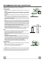
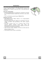
RECOMMENDATIONS AND SUGGESTIONS
The Instructions for Use apply to several versions of this appliance. Accordingly, you may find
descriptions of individual features that do not apply to your specific appliance.
INSTALLATION
• The manufacturer will not be held liable for any damages resulting from incorrect or improper
installation.
• The minimum safety distance between the cooker top and the extractor hood is 650 mm (some
models can be installed at a lower height, please refer to the paragraphs on working dimensions
and installation).
• Check that the mains voltage corresponds to that indicated on the rating plate fixed to the inside of
the hood.
• For Class I appliances, check that the domestic power supply guarantees adequate earthing.
Connect the extractor to the exhaust flue through a pipe of minimum diameter 120 mm. The route
of the flue must be as short as possible.
• Do not connect the extractor hood to exhaust ducts carrying combustion fumes (boilers, fireplaces,
etc.).
• If the extractor is used in conjunction with non-electrical appliances (e.g. gas burning appliances), a
sufficient degree of aeration must be guaranteed in the room in order to prevent the backflow of
exhaust gas. The kitchen must have an opening communicating directly with the open air in order
to guarantee the entry of clean air. When the cooker hood is used in conjunction with appliances
supplied with energy other than electric, the negative pressure in the room must not exceed 0,04
mbar to prevent fumes being drawn back into the room by the cooker hood.
• In the event of damage to the power cable, it must be replaced by the manufacturer or by the
technical service department, in order to prevent any risks.
• If the instructions for installation for the gas hob specify a greater distance specified above, this has
to be taken into account. Regulations concerning the discharge of air have to be fulfilled.
USE
• The extractor hood has been designed exclusively for domestic use to eliminate kitchen smells.
• Never use the hood for purposes other than for which it has been designed.
• Never leave high naked flames under the hood when it is in operation.
• Adjust the flame intensity to direct it onto the bottom of the pan only, making sure that it does not
engulf the sides.
• Deep fat fryers must be continuously monitored during use: overheated oil can burst into flames.
• Do not flambè under the range hood; risk of fire
• This appliance is not intended for use by persons (including children) with reduced physical, sen-
sory or mental capabilities, or lack of experience and knowledge, unless they have been given su-
pervision or instruction concerning use of the appliance by a person responsible for their safety.
• Children should be supervised to ensure that they do not play with the appliance.
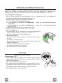
• “ CAUTION: Accessible parts may become hot when used with cooking appliances.”.
MAINTENANCE
• Switch off or unplug the appliance from the mains supply before carrying out any maintenance
work.
• Clean and/or replace the Filters after the specified time period (Fire hazard).
• Clean the hood using a damp cloth and a neutral liquid detergent.
The symbol on the product or on its packaging indicates that this product may not be treated as household waste. Instead it shall be handed over to the
applicable collection point for the recycling of electrical and electronic equipment. By ensuring this product is disposed of correctly, you will help prevent potential negative
consequences for the environment and human health, which could otherwise be caused by inappropriate waste handling of this product. For more detailed information
about recycling of this product, please contact your local city office, your household waste disposal service or the shop where you purchased the product
.
2°

EN
4
4
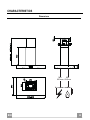
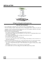
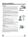
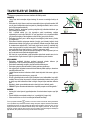
CHARACTERISTICS
Dimensions
Min.
650mm
Min.
650mm

EN
5
5
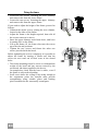
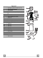
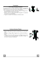
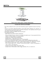
Components
Ref. Q.ty Product Components
1 1 Hood Body, complete with: Controls, Light, Blower,
Filters
2 1 Telescopic Chimney comprising:
2.1 1 Upper Section
2.2 1 Lower Section
7.1 1 Telescopic frame complete with extractor, consisting of:
7.1a 1 Upper frame
7.1b 1 Lower frame
9 1 Reducer Flange ø 150-120 mm
10 1 Flange ø 150
15 1 Air Outlet Connection
24 1 Junction box
25 Pipe clamps (not included)
Ref. Q.ty Installation Components
11 4 Wall Plugs ø 10
12c 6 Screws 2,9 x 6,5
12e 2 Screws 2,9 x 9,5
12f 2 Screws M4 x 80
12g 4 Screws M6 x 80
12h 4 Screws 5,2 x 70
12q 4 Screws 3,5 x 9,5
21 1 Drilling template
22 8 6.4 mm int. dia washers
23 4 M6 nuts
Q.ty Documentation
1 Instruction Manual
12c
7.1a
7.1
22
23
12h
7.1b
2
2.1
2.2
12c
11
21
12g
1
24
12e
15
12c
25
9
10
12f
12q
22

EN
6
6
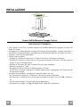
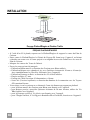
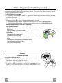
INSTALLATION
Drilling the Ceiling/shelf and fixing the frame
DRILLING THE CEILING/SHELF
• Use a plumb line to mark the centre of the hob on the ceiling/support shelf.
• Place the drilling template 21 provided on the ceiling/support shelf, making sure that the
template is in the correct position by lining up the axes of the template with those of the hob.
• Mark the centres of the holes in the template.
• Drill the holes at the points marked:
• For concrete ceilings, drill for plugs appropriate to the screw size.
• For hollow brick ceilings with wall thickness of 20 mm: drill ø 10 mm(immediately insert
the Dowels 11 supplied).
• For wooden beam ceilings, drill according to the wood screws used.
• For wooden shelf, drill ø 7 mm.
• For the power supply cable feed, drill ø 10 mm.
• For the air outlet (Ducted Version), drill according to the diameter of the external air ex-
haust duct connection.
• Insert two screws of the following type, crossing them and leaving 4-5 mm from the ceiling:
• For concrete ceilings, use the appropriate plugs for the screw size (not provided).
• for Cavity ceiling with inner space, with wall thickness of approx. 20 mm, Screws 12h,
supplied.
• For wooden beam ceilings, use 4 wood screws (not provided).
• For wooden shelf, use 4 screws 12g with washers 22 and nuts 23, provided.

EN
7
7
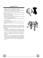
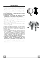
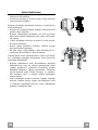
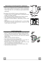
Fixing the frame
• Loosen the two screws fastening the lower chimney
and remove this from the lower frame.
• Loosen the two screws fastening the upper chimney
and remove this from the upper frame.
If you wish to adjust the height of the frame, proceed as
follows:
• Unfasten the metric screws joining the two columns,
located at the sides of the frame.
• Adjust the frame to the height required, then refit all
the screws removed as above.
• Insert the upper chimney stack from above, and leave
it running free on the frame.
• Lift up the frame, fit the frame slots onto the screws
up to the slot end positions.
• Tighten the two screws and fasten the other two
screws provided with the hood.
Before tightening the screws completely it is possible to
adjust the frame by turning it. Make sure that the
screws do not come out of their seats in the slotted
holes.
• The frame mountings must be secure to withstand the
weight of the hood and any stresses caused by the
occasional side thrust applied to the device.
On completion, check that the base is stable, even if
the frame is subjected to bending.
• In all cases where the ceiling is not strong enough at
the suspension point, the installer must provide
strengthening using suitable plates and backing
pieces anchored to the structurally sound parts.
2
2
1
1

EN
8
8
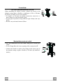
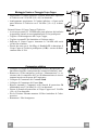
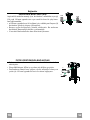
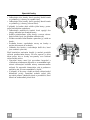
Connections
DUCTED VERSION AIR EXHAUST SYSTEM
When installing the ducted version, connect the hood to the
chimney using either a flexible or rigid pipe ø 150 or 120 mm,
the choice of which is left to the installer.
• To install a ø 120 mm air exhaust connection, insert the re-
ducer flange 9 on the hood body outlet.
• Fix the pipe in position using sufficient pipe clamps (not sup-
plied).
• Remove any activated charcoal filters.
9
ø 150
ø 120
25
25
Recirculation version air outlet
• Fix the connection 15 to the frame using the 4 screws pro-
vided.
• Fix the flange 10 to the lower opening of the connection 15.
• Connect the hood air outlet to the flange in the lower part of
the junction using a rigid or flexible ø 150 tube (by installer’s
choice).
15
10

EN
9
9
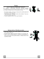
Flue assembly - Mounting the hood body
• Position the upper chimney section and fix the upper part to the
frame using the 2 screws 12c (2,9 x 6,5) provided.
• Similarly, position the lower chimney section and fix the
lower part to the frame using the 2 screws 12c (2,9 x 6,5) pro-
vided.
Before fixing the hood canopy to the frame:
• Screw the 2 screws 12f half way into the holes provided in the
sides of the bottom of the frame.
• Remove the grease filters from the hood canopy.
• Remove any activated charcoal filters.
• Lift the hood canopy and engage the screws 12f in the slots (A)
as far as they will go.
• Working from below, fix the hood canopy to the frame (B),
using the 4 screws 12q and 4 washers 22 provided, then tighten
all the screws securely.
ELECTRICAL CONNECTION
• Connect the hood to the mains through a two-pole switch hav-
ing a contact gap of at least 3 mm.
• Remove the grease filters (see paragraph Maintenance) being
sure that the connector of the feeding cable is correctly inserted
in the socket placed on the side of the fan.
• Connect the control connector Cmd.
• Connect the lights connector Lux.
• Place the connectors in the junction box 24 and close it using
the 2 screws 12e (2,9 x 9,5) provided.
• Fix the junction box to the hood body using the 2 screws 12c
(2,9 x 6,5) provided.
• For the recirculation version, fit the activated carbon odour fil-
ter.
• Replace the grease filters.
24
12e
Cmd
12c
Lux

EN
1
10
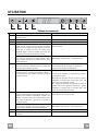
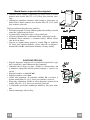
USE
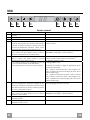
A B C D E F G H
Control panel
Button Function Display
A Turns the suction motor on and off at speed one. Displays the set speed
B Decreases the working speed. Displays the set speed
C Increases the working speed. Displays the set speed
D Activate intensive speed from any other speed,
including motor off. This speed is set to operate
for 6 minutes, after which the system returns to the
speed that was set before. Suitable to deal with
maximum levels of cooking fumes.
Displays HI and the time remaining once very second.
Press and hold the button for approximately 5
seconds, with all the loads turned off (Motor and
Lights), to turn the Activated Charcoal Filter
alarm On and Off.
FC+Punto (2 flashes)–Alarm On.
FC+Punto (1 flash)–Alarm Off.
E 24H function
Turns the suction motor on at speed one and
effects one 10 minute extraction every hour.
Displays 24 and the spot at the bottom right flashes once
every second, while the motor is running.
It is disabled by pressing the button.
When the filters alarm is triggered, the alarm can
be reset by pressing and holding this button for
approximately 3 seconds.
These indications are only visible when the motor
is turned off.
FF flashes three times.
When the procedure terminates, the indication shown
previously turns off:
FG indicates the need to wash the metal grease filters.
The alarm is triggered after the Hood has been in
operation for 100 working hours.
FC indicates the need to change the activated charcoal
filters, and also to wash the metal grease filters. The alarm
is triggered after the Hood has been in operation for 200
working hours.
F Delay function
Activate automatic switch-off with a 30’ delay.
Suitable to complete elimination of residual
odours. Can be activated from any position, and is
disabled by pressing the button or turning the
motor off.
Displays the operating speed and the spot at the bottom
right flashes once a second.
Press and hold the button for approximately 5
seconds, with all the loads turned off (Motor and
Lights), to turn the Remote Control On and Off.
IR+Punto (2 flashes)–Alarm On.
IR+Punto (1 flash)–Alarm Off.
G Turns the lighting system on and off at maximum
intensity.
H Turns the Courtesy Lighting on and off.

EN
1
11
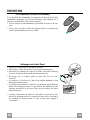
MAINTENANCE
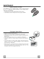
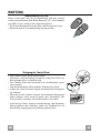
REMOTE CONTROL (OPTIONAL)
The appliance can be controlled using a remote control powered
by a 1.5 V carbon-zinc alkaline batteries of the standard LR03-
AAA type (not included).
• Do not place the remote control near to heat sources.
• Used batteries must be disposed of in the proper manner.
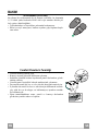
Cleaning the Comfort Panels
• Pull the Comfort Panel to open it.
• Unhook the security chain by opening the spring catch.
• Disconnect the panel from the hood canopy by sliding the fix-
ing pin lever.
• The comfort panel must never be washed in a dishwasher.
• Clean the outside by using a damp cloth and neutral liquid de-
tergent.
• Clean the inside as well by using a damp cloth and neutral de-
tergent; do not use wet cloths or sponges, or jets of water; do
not use abrasive substances.
• When the above operation has been completed, hook the panel
back and the spring catch to the hood canopy and close it by
turning the knob in the opposite direction.
11
22

EN
1
12
Metal grease filters
They can be washed in the dishwasher, and need to be cleaned
whenever the FG sign appears on the display or at least once
every 2 months use, or more frequently if use is particularly
intensive.
Resetting the alarm signal
• Turn the Lights and the Suction motor off, then disable the 24h
function, if enabled.
• Press button E (see the paragraph on Use).
Cleaning the Filters
• Open the Comfort panels by pulling on the recess.
• Remove the Filters one at a time, pushing them towards the
back of the unit and at the same time pulling downward.
• Wash the Filters without bending them, and leave them to dry
completely before replacing. (If the surface of the filter
changes colour as time goes by, this will have absolutely no
effect on the efficiency of the filter itself.)
• Replace, taking care to ensure that the handle faces forwards.
• Close the Comfort panels.

EN
1
13
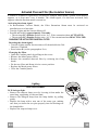
Activated Charcoal Filter (Recirculation Version)
It cannot be washed or regenerated, and must be changed when the FC symbol on the display
appears, or at least once every 4 months. The Alarm signal, if it has been activated, only
appears when the Suction motor is turned on.
Activating the alarm signal
• In Recirculation Version Hoods, the Filter Saturation Alarm must be activated on
installation or at a later date.
• Turn the Lights and the Suction Motor off.
• Press D and hold for approximately 5 Seconds:
• The message FC+Puntino flashes twice, A.C. Filter saturation alarm ACTIVATED
• The message FC+Puntino flashes once, A.C. Filter saturation alarm DEACTIVATED
CHANGING THE ACTIVATED CHARCOAL FILTER
Resetting the alarm signal
• Turn the Lights and the Suction motor off, then disable the 24h
function, if enabled.
• Press button E (see the paragraph on Use).
Changing the Filter
• Open the Comfort panels by pulling on the recess.
• Remove the Metal grease filters.
• Remove the saturated charcoal filter by releasing the fixing
hooks.
• Fit the new filter and fasten it in its correct position.
• Replace the Metal grease filters.
• Close the Comfort panels.
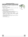
Lighting
LIGHT REPLACEMENT
20 W halogen light.
• Remove the snap-on lamp cover by levering it from under the
metal ring, supporting it with one hand.
• Remove the halogen lamp from the lamp holder by pulling
gently.
• Replace the lamp with a new one of the same type, making
sure that you insert the two pins properly into the housings on
the lamp holder.
• Replace the snap-on lamp cover.

IT
1
14
CONSIGLI E SUGGERIMENTI
Questo libretto di istruzioni per l'uso è previsto per più versioni dell' apparecchio. É possibile che siano
descritti singoli particolari della dotazione, che non riguardano il Vostro apparecchio.
INSTALLAZIONE
• Il produttore declina qualsiasi responsabilità per danni dovuti ad installazione non corretta o non conforme
alle regole dell’arte.
• La distanza minima di sicurezza tra il Piano di cottura e la Cappa deve essere di 650 mm, (alcuni modelli
possono essere installati ad un’altezza inferiore, fare riferimento ai paragrafi ingombro e installazione).
• Verificare che la tensione di rete corrisponda a quella riportata nella targhetta posta all’interno della Cappa.
• Per Apparecchi in Classe I
a
accertarsi che l’impianto elettrico domestico garantisca un corretto scarico a
terra.
• Collegare la Cappa all’uscita dell’aria aspirata con tubazione di diametro pari o superiore a 120 mm. Il
percorso della tubazione deve essere il più breve possibile.
• Non collegare la Cappa a condotti di scarico dei fumi prodotti da combustione (caldaie, caminetti, ecc.).
• Nel caso in cui nella stanza vengano utilizzati sia la Cappa che apparecchi non azionati da energia elettrica
(ad esempio apparecchi utilizzatori di gas), si deve provvedere ad una aerazione sufficiente dell’ambiente.
Se la cucina ne fosse sprovvista, praticare un’apertura che comunichi con l’esterno, per garantire il richia-
mo d’aria pulita. Un uso proprio e senza rischi si ottiene quando la depressione massima del locale non
supera i 0,04 mBar.
• In caso di danneggiamento del cavo alimentazione, esso deve essere sostituito dal costruttore o dal servi-
zio di assistenza tecnica, in modo da prevenire ogni rischio.
• Se le istruzioni di installazione del dispositivo di cottura a gas indicano che è necessaria una distanza
maggiore di quella indicato sopra, è necessario tenerne conto. Bisogna rispettare tutte le normative relative
allo scarico dell’aria.
USO
• La Cappa è stata progettata esclusivamente per uso domestico, per abbattere gli odori della cucina.
• Non fare mai uso improprio della Cappa.
• Non lasciare fiamme libere a forte intensità sotto la Cappa in funzione.
• Regolare sempre le fiamme in modo da evitare una evidente fuoriuscita laterale delle stesse rispetto al
fondo delle pentole.
• Controllare le friggitrici durante l’uso: l’olio surriscaldato potrebbe infiammarsi.
• Non preparare alimenti flambè sotto la cappa da cucina; pericolo d'incendio.
• Questo apparecchio non deve essere utilizzato da persone (bambini inclusi) con ridotte capacità psichiche,
sensoriali o mentali, oppure da persone senza esperienza e conoscenza, a meno che non siano controllati
o istruiti all’uso dell’apparecchio da persone responsabili della loro sicurezza.
• I bambini devono essere supervisionati per assicurarsi che non giochino con l’apparecchio.
• “ATTENZIONE: Le parti accessibili possono diventare molto calde se utilizzate con degli apparecchi di
cottura”.
MANUTENZIONE
• Prima di procedere a qualsiasi operazione di manutenzione, disinserire la Cappa togliendo la spina elettri-
ca o spegnendo l’interruttore generale.
• Effettuare una scrupolosa e tempestiva manutenzione dei Filtri secondo gli intervalli consigliati (Rischio di
incendio).
• Per la pulizia delle superfici della Cappa è sufficiente utilizzare un panno umido e detersivo liquido neutro.
Il simbolo sul prodotto o sulla confezione indica che il prodotto non deve essere considerato come un normale
rifiuto domestico, ma deve essere portato nel punto di raccolta appropriato per il riciclaggio di apparecchiature elettriche
ed elettroniche. Provvedendo a smaltire questo prodotto in modo appropriato, si contribuisce a evitare potenziali conse-
guenze negative per l’ambiente e per la salute, che potrebbero derivare da uno smaltimento inadeguato del prodotto.
Per informazioni più dettagliate sul riciclaggio di questo prodotto, contattare l’ufficio comunale, il servizio locale di smalti-
mento rifiuti o il negozio in cui è stato acquistato il prodotto.
2°

IT
1
15
CARATTERISTICHE
Ingombro
Min.
650mm
Min.
650mm

IT
1
16
Componenti
Rif. Q.tà Componenti di Prodotto
1 1 Corpo Cappa completo di: Comandi, Luce, Filtri
2 1 Camino telescopico formato da:
2.1 1 Camino superiore
2.2 1 Camino inferiore
7.1 1 Traliccio telescopico completo di Aspiratore, formato
da:
7.1a 1 Traliccio superiore
7.1b 1 Traliccio inferiore
9 1 Flangia di riduzione ø 150-120 mm
10 1 Flangia ø 150
15 1 Raccordo Uscita Aria
24 1 Scatola connessioni
25 Fascette stringitubo (non incluse)
Rif. Q.tà Componenti di Installazione
11 4 Tasselli ø 10
12c 6 Viti 2,9 x 6,5
12e 2 Viti 2,9 x 9,5
12f 2 Viti M4 x 80
12g 4 Viti M6 x 80
12h 4 Viti 5,2 x 70
12q 4 Viti 3,5 x 9,5
21 1 Dima di foratura
22 8 Rondelle ø 6,4
23 4 Dadi M6
Q.tà Documentazione
1 Libretto Istruzioni
12c
7.1a
7.1
22
23
12h
7.1b
2
2.1
2.2
12c
11
21
12g
1
24
12e
15
12c
25
9
10
12f
12q
22

IT
1
17
INSTALLAZIONE
Foratura Soffitto/Mensola e Fissaggio Traliccio
FORATURA SOFFITTO/MENSOLA
• Con l’ausilio di un Filo a piombo riportare sul Soffitto/Mensola di supporto il centro del
Piano di Cottura.
• Appoggiare al Soffitto/Mensola la Dima di Foratura 21 in dotazione, facendo coincidere il
suo centro al centro proiettato e allineando gli assi della Dima agli assi del Piano di Cottura.
• Segnare i centri dei Fori della Dima.
• Forare i punti seguenti:
• Soffitto in Calcestruzzo massiccio: secondo Tasselli per Calcestruzzo impiegati.
• Soffitto in Laterizio a camera d’aria, con spessore resistente di 20 mm: ø 10 mm (inserire
subito i Tasselli 11 in dotazione).
• Soffitto in Travatura di Legno: secondo Viti per Legno impiegate.
• Mensola in Legno: ø 7 mm.
• Passaggio del Cavo elettrico di Alimentazione: ø 10 mm.
• Uscita Aria (Versione Aspirante): secondo diametro del collegamento alla Tubazione di
Evacuazione Esterna.
• Avvitare, incrociandole e lasciando 4-5 mm dal soffitto, due viti:
• per Calcestruzzo massiccio, Tasselli per Calcestruzzo, non in dotazione.
• per Laterizio a camera d’aria, con spessore resistente di 20 mm circa, Viti 12h, in dotazio-
ne.
• per Travatura di legno, Viti per legno, non in dotazione.
• per Mensola in Legno, viti 12g con Rondelle 22 e Dadi 23, in dotazione.

IT
1
18
Fissaggio Traliccio
• Svitare le due viti che fissano il camino inferiore e
sfilarlo dal traliccio (dalla parte inferiore).
• Svitare le due viti che fissano il camino superiore e
sfilarlo dal traliccio (dalla parte superiore).
Nel caso in cui si voglia regolare l’altezza del traliccio
procedere come segue:
• Svitare le viti metriche che uniscono le due colonne,
poste ai lati del traliccio;
• Regolare l’altezza desiderata del traliccio e riavvitare
le viti precedentemente tolte;
• Inserire il camino superiore dall’ alto e lasciarlo libe-
ro sul traliccio;
• Sollevare il traliccio, incastrare le asole sulle viti e
scorrere fino a battuta;
• Stringere le due viti e avvitare le altre due in dotazio-
ne;
Prima di serrare definitivamente le viti è possibile effet-
tuare delle regolazioni spostando il traliccio, facendo
attenzione che le viti non escano dalla sede dell’asola di
regolazione.
• Il fissaggio del Traliccio deve essere sicuro in rela-
zione sia al peso della Cappa sia alle sollecitazioni
causate da occasionali spinte laterali all’Apparecchio
montato. A fissaggio avvenuto verificare quindi che
la base sia stabile anche se il Traliccio è sollecitato a
flessione.
• In tutti i casi in cui il Soffitto non fosse sufficiente-
mente robusto sul punto di sospensione, l’Installatore
dovrà provvedere a irrobustirlo con opportune piastre
e contropiastre ancorate a parti strutturalmente resi-
stenti.
2
2
1
1

IT
1
19
Connessioni
USCITA ARIA VERSIONE ASPIRANTE
Per installazione in Versione Aspirante collegare la Cappa alla
tubazione di uscita per mezzo di un tubo rigido o flessibile di
ø150 o 120 mm, la cui scelta è lasciata all'installatore.
• Per collegamento con tubo ø120 mm, inserire la Flangia di ri-
duzione 9 sull’Uscita del Corpo Cappa.
• Fissare il tubo con adeguate fascette stringitubo. Il materiale
occorrente non è in dotazione.
• Togliere eventuali Filtri Antiodore al Carbone attivo.
9
ø 150
ø 120
25
25
Uscita aria Versione Filtrante
• Fissare il Raccordo 15 al traliccio utilizzando le 4 Viti in dota-
zione.
• Incastrare la flangia 10 nell’apposito foro inferiore del Raccor-
do 15.
• Collegare l’uscita aria della cappa con la flangia posta sotto al
raccordo per mezzo di un tubo rigido o flessibile ø 150mm , la
cui scelta è lasciata all’installatore
15
10

IT
2
20
Montaggio Camino e Fissaggio Corpo Cappa
• Posizionare il Camino superiore e fissare nella parte superiore
al Traliccio con 2 Viti 12c (2,9 x 6,5) in dotazione.
• Analogamente posizionare il Camino inferiore e fissare nella
parte inferiore al Traliccio con 2 Viti 12c (2,9 x 6,5) in dota-
zione.
Prima di fissare il Corpo Cappa al Traliccio:
• Avvitare per metà le 2 Viti 12f sulla parte inferiore del traliccio
in posizione laterale in corrispondenza dei 2 fori predisposti.
• Togliere i Filtri antigrasso dal Corpo Cappa;
• Togliere eventuali Filtri Antiodore al Carbone attivo.
• Sollevare il Corpo Cappa e incastrare le Viti 12f sulle asole
(rif.A) fino a battuta.
• Fissare da sotto con 4 Viti 12q e 4 Rondelle 22 in dotazione il
Corpo Cappa al Traliccio predisposto (rif.B) e serrare definiti-
vamente tutte le Viti.
Connessione elettrica
• Collegare la Cappa all’Alimentazione di Rete interponendo un
Interruttore bipolare con apertura dei contatti di almeno 3 mm.
• Rimuovere i Filtri antigrasso (vedi par. “Manutenzione”) e as-
sicurarsi che il connettore del Cavo di alimentazione sia corret-
tamente inserito nella presa dell’Aspiratore
• Collegare il Connettore dei Comandi Cmd.
• Collegare il Connettore dei Faretti Lux.
• Riporre entrambi i Connettori nella Scatola di protezione 24
chiudendola con 2 Viti 12e(2,9 x 9,5) in dotazione.
• Fissare la Scatola di protezione al Corpo Cappa con 2 Viti 12c
(2,9 x 6,5) in dotazione.
• Per la Versione Filtrante montare il Filtro Antiodore al Carbo-
ne attivo.
• Rimontare i Filtri Antigrasso.
24
12e
Cmd
12c
Lux
Sayfa yükleniyor...
Sayfa yükleniyor...
Sayfa yükleniyor...
Sayfa yükleniyor...
Sayfa yükleniyor...
Sayfa yükleniyor...
Sayfa yükleniyor...
Sayfa yükleniyor...
Sayfa yükleniyor...
Sayfa yükleniyor...
Sayfa yükleniyor...
Sayfa yükleniyor...
Sayfa yükleniyor...
Sayfa yükleniyor...
Sayfa yükleniyor...
Sayfa yükleniyor...
Sayfa yükleniyor...
Sayfa yükleniyor...
Sayfa yükleniyor...
Sayfa yükleniyor...
Sayfa yükleniyor...
Sayfa yükleniyor...
Sayfa yükleniyor...
Sayfa yükleniyor...
Sayfa yükleniyor...
Sayfa yükleniyor...
Sayfa yükleniyor...
Sayfa yükleniyor...
Sayfa yükleniyor...
Sayfa yükleniyor...
Sayfa yükleniyor...
Sayfa yükleniyor...
Sayfa yükleniyor...
Sayfa yükleniyor...
Sayfa yükleniyor...
Sayfa yükleniyor...
Sayfa yükleniyor...
Sayfa yükleniyor...
Sayfa yükleniyor...
Sayfa yükleniyor...
Sayfa yükleniyor...
Sayfa yükleniyor...
Sayfa yükleniyor...
Sayfa yükleniyor...
Sayfa yükleniyor...
Sayfa yükleniyor...
Sayfa yükleniyor...
Sayfa yükleniyor...
Sayfa yükleniyor...
Sayfa yükleniyor...
Sayfa yükleniyor...
Sayfa yükleniyor...
-
 1
1
-
 2
2
-
 3
3
-
 4
4
-
 5
5
-
 6
6
-
 7
7
-
 8
8
-
 9
9
-
 10
10
-
 11
11
-
 12
12
-
 13
13
-
 14
14
-
 15
15
-
 16
16
-
 17
17
-
 18
18
-
 19
19
-
 20
20
-
 21
21
-
 22
22
-
 23
23
-
 24
24
-
 25
25
-
 26
26
-
 27
27
-
 28
28
-
 29
29
-
 30
30
-
 31
31
-
 32
32
-
 33
33
-
 34
34
-
 35
35
-
 36
36
-
 37
37
-
 38
38
-
 39
39
-
 40
40
-
 41
41
-
 42
42
-
 43
43
-
 44
44
-
 45
45
-
 46
46
-
 47
47
-
 48
48
-
 49
49
-
 50
50
-
 51
51
-
 52
52
-
 53
53
-
 54
54
-
 55
55
-
 56
56
-
 57
57
-
 58
58
-
 59
59
-
 60
60
-
 61
61
-
 62
62
-
 63
63
-
 64
64
-
 65
65
-
 66
66
-
 67
67
-
 68
68
-
 69
69
-
 70
70
-
 71
71
-
 72
72


Franke FDB 10078 I Instructions for Use and Installation
- Kategori
- Ocak davlumbazları
- Tip
- Instructions for Use and Installation
- Bu kılavuz aynı zamanda aşağıdakiler için de uygundur:
diğer dillerde
- slovenčina: Franke FDB 10078 I
- français: Franke FDB 10078 I
- italiano: Franke FDB 10078 I
- Deutsch: Franke FDB 10078 I
- English: Franke FDB 10078 I
İlgili makaleler
-
Franke FMY 907 FM Kullanım kılavuzu
-
Franke FSTPRO 608 X Extractor Hood Kullanım kılavuzu
-
Franke TALE 905 I Hood Stainless Steel Kullanım kılavuzu
-
-
Franke TRENDLINE PLUS BK 70 Matt Black Kullanım kılavuzu
-
Franke FSMD 508 smart Deco matt smokey Blue Kullanım kılavuzu
-
-
Franke FMA 2.0 607 Kullanım kılavuzu
-
Franke FSTP NG 605 X Kullanım kılavuzu
-
Franke FPJ 615 V BK A Kullanım kılavuzu
Diğer belgeler
-
V-ZUG DEHMR 5 Kullanma talimatları
-
Aeg-Electrolux X92384MI0 Kullanım kılavuzu
-
AEG DI7490-M Kullanım kılavuzu
-
Electrolux EFA9620X Kullanım kılavuzu
-
Electrolux EFA90540X Kullanım kılavuzu
-
-
ELICA Meridiana EDS IX VT/A/120X70 Yükleme Rehberi
-
 Franke Consumer Products FDF 9044 I Kullanım kılavuzu
-
 Franke Consumer Products FGC 906 I Kullanım kılavuzu
-
 Franke Consumer Products Cooktop FPL 607 I XS 645H Kullanım kılavuzu


