
DOC022.98.80363
BODTrak II
10/2019, Edition 2
Basic User Manual
Basis-Benutzerhandbuch
Manuale di base per l'utente base
Manuel d'utilisation de base
Manual básico del usuario
Manual básico do utilizador
Basisgebruikershandleiding
Podstawowa instrukcja obsługi
Grundläggande bruksanvisning
Основно ръководство за потребителя
Alapvető felhasználói útmutató
Manual de utilizare de bază
Temel Kullanım Kılavuzu
Βασικό εγχειρίδιο χρήστη

Table of Contents
English...................................................................................................................................................................................................3
Deutsch...............................................................................................................................................................................................14
Italiano................................................................................................................................................................................................. 26
Français.............................................................................................................................................................................................. 38
Español............................................................................................................................................................................................... 50
Português.......................................................................................................................................................................................... 62
Nederlands........................................................................................................................................................................................ 74
Polski................................................................................................................................................................................................... 86
Svenska.............................................................................................................................................................................................. 98
български....................................................................................................................................................................................... 108
Magyar.............................................................................................................................................................................................. 120
Română............................................................................................................................................................................................ 132
Türkçe................................................................................................................................................................................................144
Ελληνικά........................................................................................................................................................................................... 155
2

Table of Contents
1 Specifications on page 3
2 General information on page 3
3 Installation on page 5
4 User interface on page 6
5 Startup on page 7
6 Standard operation on page 7
7 Maintenance on page 9
8 Troubleshooting on page 10
9 Replacement parts and accessories
on page 11
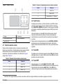
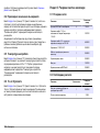
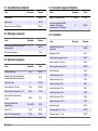
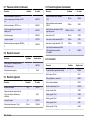
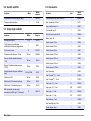
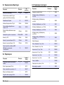
Section 1 Specifications
Specifications are subject to change without notice.
Table 1 General Specifications
Specification Details
Operating
temperature
5 to 40 ºC (41 to 104 ºF)
Altitude limit 2000 m (6500 ft)
Pollution degree 2
Installation
category
II
Storage/operating
humidity
Maximum relative humidity is 80% for temperatures up to
31 ºC (87.8 ºF), decreases linearly to 50% relative
humidity at 40 ºC (104 ºF)
Location Laboratory / Indoor
Protection class 2
Range Selectable, 0 to 35, 0 to 70, 0 to 350, 0 to 700 mg/L
Dimensions 28.9 x 26 x 9.8 cm (11.375 x 10.25 x 3.875 in.)
External power
supply
Input: 100 to 240 VAC, 50/60 Hz, 1.5 A; Output: 24 VDC,
2.7 A, UL CSA and TUV approved.
Capacity Six 492 mL bottles
Table 1 General Specifications (continued)
Specification Details
Shipping weight 4 kg (8.8 lb)
Warranty 1 year (EU 2 years)
Table 2 Method performance specifications
Specification Details
Precision Parameters:
• Standard: 150 mg/L each of glucose and glutamic acid
• Number of samples: 44
• Number of analysts: 1
• Number of BodTrak II instruments: 6
Results:
• Mean of 235 mg/L BOD
• Distribution: 11 mg/L or range of 224 to 246 mg/L BOD
• 95% confidence limit
Drift Less than 3 mg/L BOD in 5 days
Resolution 1 mg/L BOD
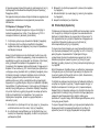
Section 2 General information
In no event will the manufacturer be liable for direct, indirect, special,
incidental or consequential damages resulting from any defect or
omission in this manual. The manufacturer reserves the right to make
changes in this manual and the products it describes at any time, without
notice or obligation. Revised editions are found on the manufacturer’s
website.
2.1 Expanded manual version
For additional information, refer to the CD for an expanded version of
this manual.
English
3

2.2 Safety information
N O T I C E
The manufacturer is not responsible for any damages due to misapplication or
misuse of this product including, without limitation, direct, incidental and
consequential damages, and disclaims such damages to the full extent permitted
under applicable law. The user is solely responsible to identify critical application
risks and install appropriate mechanisms to protect processes during a possible
equipment malfunction.
Please read this entire manual before unpacking, setting up or operating
this equipment. Pay attention to all danger and caution statements.
Failure to do so could result in serious injury to the operator or damage
to the equipment.
Make sure that the protection provided by this equipment is not impaired.
Do not use or install this equipment in any manner other than that
specified in this manual.
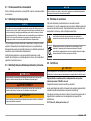
2.3 Use of hazard information
D A N G E R
Indicates a potentially or imminently hazardous situation which, if not avoided, will
result in death or serious injury.
W A R N I N G
Indicates a potentially or imminently hazardous situation which, if not avoided,
could result in death or serious injury.
C A U T I O N
Indicates a potentially hazardous situation that may result in minor or moderate
injury.
N O T I C E
Indicates a situation which, if not avoided, may cause damage to the instrument.
Information that requires special emphasis.
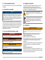
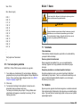
2.4 Precautionary labels
Read all labels and tags attached to the instrument. Personal injury or
damage to the instrument could occur if not observed. A symbol on the
instrument is referenced in the manual with a precautionary statement.
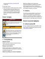
This symbol, if noted on the instrument, references the instruction
manual for operation and/or safety information.
Electrical equipment marked with this symbol may not be disposed of
in European domestic or public disposal systems. Return old or end-
of-life equipment to the manufacturer for disposal at no charge to the
user.
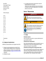
2.5 Certification
C A U T I O N
This equipment is not intended for use in residential environments and may not
provide adequate protection to radio reception in such environments.
Canadian Radio Interference-Causing Equipment Regulation,
ICES-003, Class A:
Supporting test records reside with the manufacturer.
This Class A digital apparatus meets all requirements of the Canadian
Interference-Causing Equipment Regulations.
Cet appareil numérique de classe A répond à toutes les exigences de la
réglementation canadienne sur les équipements provoquant des
interférences.
FCC Part 15, Class "A" Limits
Supporting test records reside with the manufacturer. The device
complies with Part 15 of the FCC Rules. Operation is subject to the
following conditions:
1. The equipment may not cause harmful interference.
2. The equipment must accept any interference received, including
interference that may cause undesired operation.
4
English

Changes or modifications to this equipment not expressly approved by
the party responsible for compliance could void the user's authority to
operate the equipment. This equipment has been tested and found to
comply with the limits for a Class A digital device, pursuant to Part 15 of
the FCC rules. These limits are designed to provide reasonable
protection against harmful interference when the equipment is operated
in a commercial environment. This equipment generates, uses and can
radiate radio frequency energy and, if not installed and used in
accordance with the instruction manual, may cause harmful interference
to radio communications. Operation of this equipment in a residential
area is likely to cause harmful interference, in which case the user will be
required to correct the interference at their expense. The following
techniques can be used to reduce interference problems:
1. Disconnect the equipment from its power source to verify that it is or
is not the source of the interference.
2. If the equipment is connected to the same outlet as the device
experiencing interference, connect the equipment to a different
outlet.
3. Move the equipment away from the device receiving the interference.
4. Reposition the receiving antenna for the device receiving the
interference.
5. Try combinations of the above.
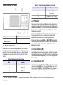
2.6 Product overview
Respirometric Biological Oxygen Demand (BOD) is a test that measures
the quantity of oxygen consumed by bacteria that oxidize organic matter
in a water sample. The test is used to measure waste loadings at
wastewater treatment plants and to examine the efficiency of wastewater
treatment.
The instrument is sealed to prevent external atmospheric pressure
changes in the test bottle. The pressure in the sample bottles is
monitored. Bacteria in the sample use oxygen when they consume
organic matter. This oxygen consumption causes the pressure in the
bottle head space to drop. The pressure drop correlates directly to BOD.
During a test period, stir bars mix the sample and cause oxygen to move
from the air in the bottle to the sample. This helps simulate natural
conditions.
Carbon dioxide is a result of the oxidation process and can interfere with
a measurement. The instrument continuously removes carbon dioxide
from the system so that the monitored pressure difference stays
proportional to the quantity of oxygen used. Pressure changes in the
closed system are shown graphically in milligrams per liter (mg/L) on a
liquid crystal display. The instrument gives 360 uniform data points over
the selected time period.
The instrument adjusts for any negative errors produced when heat is
applied to a sample. The instrument does not start the test until the
temperature gets to equilibrium.
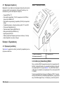
2.7 Product components
Make sure that all components have been received. If any of these items
are missing or damaged, contact the manufacturer or a sales
representative immediately.
• BODTrak
™
II instrument
• A UL/CSA approved 115 VAC power cord with a NEMA 5-15P style
plug
• A 230 VAC harmonized power cord with a continental European plug
• Power supply, auto-switching between 115 V and 230 V
• Seal cups (6x)
• BODTrak II amber sample bottles (6x)
• BODTrak II magnetic stir bars (6x)
• Spatula scoop
• Nutrient buffer solution pillows (1 pkg)
• Potassium hydroxide pellets (1 container)
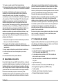
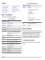
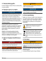
Section 3 Installation
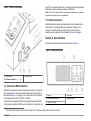
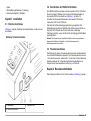
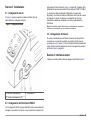
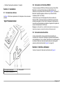
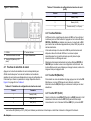
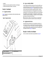
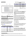
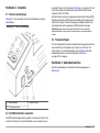
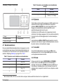
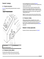
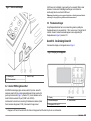
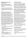
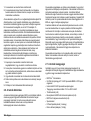
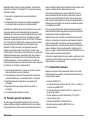
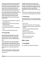
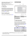
3.1 External connections
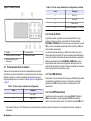
Figure 1 shows the locations of the power switch and external
connections.
English
5

Figure 1 External connections
1 Power switch 3 Serial I/O port
2 DC power connector
3.2 Connect the RS232 interface
All RS232 connections are made through the serial I/O port. Connect the
9-pin D connector of a computer interface cable to the serial I/O port on
the instrument (Figure 1 on page 6). Connect the other end of the cable
to the computer serial I/O port (COM 1 or COM 2).
The instrument is equipped as Data Communication Equipment (DCE).
The instrument operates at 9600 baud with 8 data bits, no parity and one
stop bit. The computer or printer will not receive complete transmissions
if the device cannot continuously receive at 9600 baud.
Note: The use of the specified cable or an equivalent shielded cable is necessary
to meet radio frequency emissions requirements.
3.3 Bottle connections
Each bottle position/channel has the applicable tube numbered with a
plastic sleeve. The bottle positions are numbered 1 through 6 with
number 1 in the back left corner of the chassis. Use the channel
selection keys as a guide to the bottle positions Figure 2 on page 6.
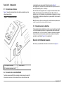
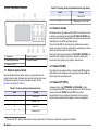
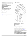
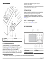
Section 4 User interface
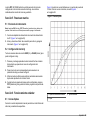
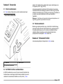
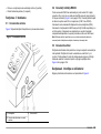
The instrument display and the keypad are shown in Figure 2.
Figure 2 Display and keypad
1 Display 4 Arrow keys
2 Channel selection keys 5 Power indicator
3 ON and OFF keys
1
1
The ON and OFF keys are used to start and stop a test. They do not power the instrument on and off.
6 English

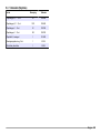
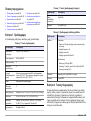
4.1 Channel selection keys
Push the related channel selection key to show data for one of the six
bottles. The channel selection keys are also used in the instrument setup
menu to select a parameter to be edited. Refer to Figure 2 on page 6
and Table 3.
Table 3 Channel key setup parameters
Channel Parameter
1 Year (0–99)
2 Month (1–12)
3 Day (1–31)
4 Hour (0–24)
5 Minute (0–59)
6 Test length (5, 7 or 10 days)
4.2 Arrow keys
The display shows a graph of BOD values on the vertical axis and time
in days on the horizontal axis. Push the LEFT and RIGHT arrows to
move the cursor along the BOD curve to show the approximate
coordinates (time, BOD) of the selected data point.
The time interval and BOD value of the data point are shown in the lower
right of the display. The cursor is automatically placed at the most
recently collected data point in a channel display.
Push and hold the LEFT and RIGHTarrows at the same time to go into
the instrument setup menu. The arrow keys are also used to change the
time, date, test length and range.
4.3 ON key
To go to the range selection menu, push ON from a channel display
screen. Then push and hold ON to start the test for the selected channel.
4.4 OFF key
When a test is in DELAY or RUN modes, push and hold OFF to
manually end the test. The instrument will show END. The OFF key is
also used to exit the instrument setup menu or range selection menu.
The changes made before the menu is exited are saved.
Section 5 Startup
5.1 Turn the instrument on
Note: The ON and OFF keys are used to start and stop a test. They do not power
the instrument on and off.
1. Connect the power adaptor to the DC power connector (Figure 1
on page 6).
2. Toggle the power switch to set the instrument to on and off. (Figure 1
on page 6).
5.2 Set the clock
All the channels must show END or CLEAR before the clock can be set.
1. Push and hold the two arrow keys at the same time until the
instrument setup menu is shown.
2. Push the applicable channel key to select the clock parameter to be
adjusted.
3. Use the arrow keys to edit the selected parameter. Adjust each
parameter in the same manner.
4. When all the time adjustments are complete, push OFF to save and
go back to the data display screen.
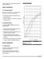
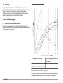
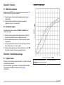
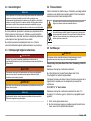
Section 6 Standard operation
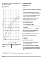
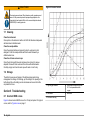
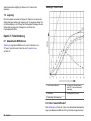
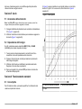
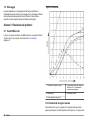
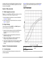
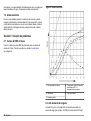
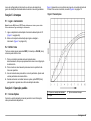
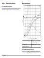
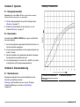
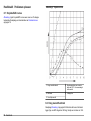
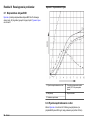
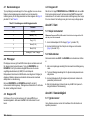
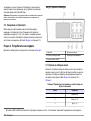
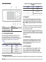
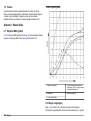
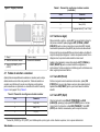
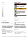
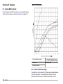
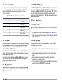
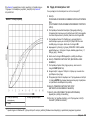
6.1 Typical curves
Refer to the expanded version of the manual for information about
specific procedures.
English
7

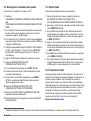
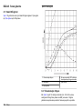
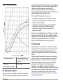
Figure 3 shows typical curves through a 10 day test period. For incorrect
curves, refer to Figure 4 on page 10.
Figure 3 Typical curves
1 Typical with substrate variation 3 Typical with time lag
2 Typical
6.2 Download test results
To transfer test results to a PC
2
:
1. Select
PROGRAMS>ACCESSORIES>COMMUNICATIONS>HYPERTERM
INAL.
2. In the Connection Description window, type in a name for the
connection and select an icon to represent the connection. Click OK.
3. In the Connect To window, use the drop-down menu to select the
COM port connected to the instrument. Click OK.
4. Configure the COM port properties: BPS = 9600, Data Bits = 8,
Parity = None, Stop Bits = 1, Flow Control = None.
5. Click OK. The connector indicator shows.
6. Select TRANSFER>CAPTURE TEXT.
7. In the Capture Text window, click START.
8. Power the instrument on. Push the key for the channel that has data
to be downloaded.
9. Type GA in the HyperTerminal window and push ENTER. The
transfer is complete when the screen stops adding new data.
10. Select TRANSFER>CAPTURE TEXT>STOP.
11. Select CALL>DISCONNECT. The disconnected indicator shows.
12. To end the HyperTerminal session, select FILE>EXIT.
6.3 Import data
To import the data from the captured text file:
1. Open a new or existing spreadsheet. Select DATA>IMPORT
EXTERNAL DATA>IMPORT DATA.
2. Select the text file captured in HyperTerminal. Click IMPORT.
3. In the Text Import Wizard, select Delimited as the file type, the start
row in the spreadsheet and Windows (ANSI) as the file origin. Click
NEXT.
2
Installed on Windows XP or older. On newer Windows versions the installation of a terminal software is necessary.
8 English

4. Click the check boxes for Space delimiter and Treat consecutive
delimiters as one. Click NEXT.
5. Select General as the column data format, then click FINISH.
6. In the Import Data window, select Existing worksheet. Select the
starting cell, then click OK. The data will appear in the spreadsheet.
6.4 Data format
The example shows the channel number, start date, start time and the
format of the downloaded data. BOD values in mg/L follow. Only the first
data points of a maximum of 360 equal distance points are shown. Each
line ends with a carriage return and a line feed. The end of the data
stream is shown by a message such as "Test Run to Completion" and a
dollar symbol ($).
If small negative BOD values are seen at the start of a test, refer to
Troubleshooting on page 10.
Example of the data format
BOD Log for Ch 1
Status: END
Full Scale: 700 mg/L
Tst length: 7 days
Start Date: 3/3/08
Time: 13:04
Days, Reading (mg/L)
0.00, 0
0.05, 10
0.11, 12
0.16, 12
0.22, 14
0.27, 14
0.33, 12
0.38, 8
0.44, 10
0.50, 12
0.55, 12
0.61, 14
-
-
-
Test Run to Completion
$
6.5 Print test results
The BODTrak II is applicable to use with the Citizen PD-24 printer.
1. Connect the printer cable to the serial I/O port on the instrument. Use
the gender adapter supplied with the printer to make the connection.
Make sure that the printer settings are correct (Connect the RS232
interface on page 6).
2. Power on the instrument.
3. Push and hold the applicable channel number for approximately
5 seconds at any time during a test.
The test results move from the instrument to the printer. The
instrument sends a copy of the graphical display and a truncated
data stream (127 data points).
Section 7 Maintenance
D A N G E R
Multiple hazards. Only qualified personnel must conduct the tasks
described in this section of the document.
English 9

C A U T I O N
Chemical exposure hazard. Obey laboratory safety procedures and
wear all of the personal protective equipment appropriate to the
chemicals that are handled. Refer to the current safety data sheets
(MSDS/SDS) for safety protocols.
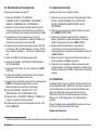
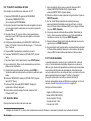
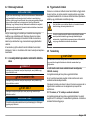
7.1 Cleaning
Clean the instrument
Clean spills on the instrument with a soft cloth that has been dampened
with deionized or distilled water.
Clean the sample bottles
Clean the sample bottles and caps with a brush, water and a mild
detergent. Flush the sample bottles with fresh water followed by a
distilled water rinse.
Clean the stir bars and seal cups
Clean the stir bars with hot water and soap. Use a brush to remove
deposits. Rinse with fresh water and then rinse with distilled water.
Carefully empty and rinse the seal cups with water. Invert to dry.
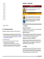
7.2 Storage
The bottle fences prevent tipping of the bottles and provide tubing
management in storage. For storage, put the tubing in the opening in the
bottle fence. Move the tubing counter-clockwise and secure the bottle
cap inside the fence.
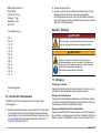
Section 8 Troubleshooting
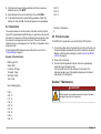
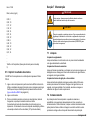
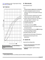
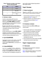
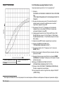
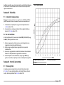
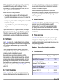
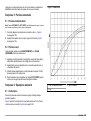
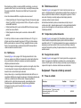
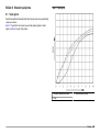
8.1 Incorrect BOD curves
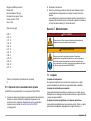
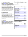
Figure 4 shows incorrect BOD curves for a 10 day test period. For typical
curves, refer to Typical curves on page 7.
Figure 4 Incorrect curves
1 High oxygen demand 4 Initial sample temperature below
20 ºC or supersaturated with
oxygen
2 Nitrification 5 Bottle leak
3 Excessive time lag
10 English

8.2 High oxygen demand
Refer to Figure 4 on page 10. Samples that are above range (for
example, a BOD over 350 mg/L when a 160-mL sample is taken) will
cause results as shown in Curve 1. Dilute the sample or use a higher
BOD range and a different sample volume. Refer to the Sample dilution,
Simplified procedure, Hach GGA procedure or the Hach Standard
method procedure for more information.
When the BOD range of a sample is unknown:
• Use the results from the Chemical Oxygen Demand (COD test).
Multiply the COD by 0.68 to get an estimated BOD value.
• Use the results from a series of BOD tests that use the same sample
but different volumes.
• Use dilution ratios to select an applicable BOD range.
Typically, effluent is in the 0–70 mg/L range while influent is in the
0-700 mg/L range. when the BOD of the sample is more than 700 mg/L,
prepare a sample dilution. Refer to the Sample dilution section in the
expanded version of this manual for more information.
8.3 Nitrification
Refer to Figure 4 on page 10. The condition shown by Curve 2 is an
example of nitrification. Deviation from the typical curve (shown as the
dashed line) is apparent by the concave increase near the end of the
test period.
Biological oxidation of organic nitrogen usually occurs after 5 days with
typical domestic waste. Nitrifying bacteria develop more slowly than
other types of bacteria.
Some samples contain a high concentration of nitrifying bacteria and
nitrification results can occur sooner. Control nitrification problems with
Hach Nitrification Inhibitor. Dispense the inhibitor powder into an empty
sample bottle and then add the sample. With the Hach Dispenser cap,
dispense 6 shots (approximately 0.48 grams) into the empty bottle. Refer
to Optional reagents on page 12.
8.4 Excessive time lag
Refer to Figure 4 on page 10. Curve 3 shows a test that did not start with
sufficient bacteria during the incubation period. To do a test on a sample
without sufficient bacteria, seed the sample. Refer to the Seed the
sample section in the expanded version of this manual for more
information.
Bacteria acclimation also causes conditions that can cause curve 3. This
sometimes occurs with standards and added seed. Add more seed or
select a different seed source.
8.5 Sample temperature
Refer to Figure 4 on page 10. The initial negative results of Curve
4 show that the initial sample temperature was below the specified range
of 20 ±1 ºC. A sample supersaturated with oxygen will also show this
type of curve. Refer to the Sample temperature and Supersaturation
sections in the expanded version of this manual for more information.
8.6 Bottle leak
Refer to Figure 4 on page 10. Curve 5 shows a bottle leak. A bottle leak
makes the system unresponsive. If such a condition occurs, examine the
seal cup and bottle cap for contamination or damage.
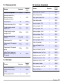
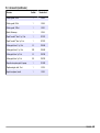
Section 9 Replacement parts and accessories
9.1 Replacement parts
Description Quantity Item no.
Bottle, BODTrak II, amber 6 714421
Power cord, 7.5 ft, for North American
115 VAC use
1 1801000
Power Cord, 8 ft, with continental
European plug for 230 VAC use
1 4683600
Power supply, 115/230 VAC 1 2952500
Computer cable for data transfer to PC 1 2959300
English 11

9.1 Replacement parts (continued)
Description Quantity Item no.
Seal cup 1 2959500
Spatula scoop 1 1225700
Stir bar, magnetic, BODTrak II 1 2959400
9.2 Required reagents
Description Quantity Item number
Respirometric BOD nutrient buffer pillows 1 2962266
Potassium hydroxide pellets 1 31425
9.3 Optional reagents
Description Quantity Item no.
Nitrification inhibitor 35 g 253335
Dispenser cap for 35 g bottle (for use with
nitrification inhibitor)
1 45901
Polyseed inoculum 50 2918700
Potassium iodide solution, 100 g/L 500 mL 1228949
Sodium Hydroxide standard solution,
1.0 N
900 mL 104553
Sodium Thiosulfate standard solution,
0.025 N
1000 mL 35253
Starch indicator solution, dropping bottle 1000 mL MDB 34932
Sulfuric acid, ACS 500 mL 97949
Sulfuric acid, 0.02 N standard solution 1000 mL 20353
9.3 Optional reagents (continued)
Description Quantity Item no.
Sulfuric acid, 1.0 N standard solution 1000 mL 127053
Voluette ampule standard for BOD,
3000 mg/L for manometric, 10-
mL/ampule
16 1486610
9.4 Accessories
Description Quantity Item number
Ampule breaker kit for voluette ampules 1 2196800
Bottle, wash, 500 mL 1 62011
Bottle, polyethylene, with spigot, 4 L 1 1486817
Brush, cylinder, size 2 1 68700
Buret, straight stopcock, 25 mL 1 1405940
Clamp, buret, double 1 32800
Cylinder, graduated, 10-mL 1 50838
Cylinder, graduated, 25-mL 1 50840
Cylinder, graduated, 50-mL 1 50841
Cylinder, graduated, 100-mL 1 50842
Cylinder, graduated, 250-mL 1 50846
Cylinder, graduated, 500-mL 1 50849
Cylinder, graduated, 1000-mL 1 50853
Flask, Erlenmeyer 1 50546
Pipet, Tensette
®
, 0.1 to 1.0 mL 1 1970001
Pipet, Tensette
®
, 1 to 10 mL 1 1970010
Pipet tips, 0.1 to 1.0 mL 50 2185696
12 English

9.4 Accessories (continued)
Description Quantity Item number
Pipet tips, 0.1 to 1.0 mL 1000 2185628
Pipet tips, 1 to 10 mL 50 2199796
Pipet tips, 1 to 10 mL 250 2199725
Pipet filler, 3 valve 1 1218900
Pipet serological, glass, 10-mL 1 53238
Support stand, buret 1 32900
English 13

Inhaltsverzeichnis
1 Technische Daten auf Seite 14
2 Allgemeine Informationen
auf Seite 14
3 Installation auf Seite 17
4 Benutzerschnittstelle auf Seite 17
5 Inbetriebnahme auf Seite 19
6 Standardbetrieb auf Seite 19
7 Wartung auf Seite 21
8 Fehlerbehebung auf Seite 22
9 Ersatzteile und Zubehör
auf Seite 24
Kapitel 1 Technische Daten
Änderungen vorbehalten.
Tabelle 1 Weitere Technische Daten
Technische Daten Details
Betriebstemperatur 5 bis 40 ºC (41 bis 104 ºF)
Maximale
Einsatzhöhe
2000 m (6500 Fuß)
Verschmutzungsgr
ad
2
Installationskategori
e
II
Luftfeuchtigkeit
Lagerung/Betrieb
Die maximale relative Feuchte beträgt 80 % bei
Temperaturen bis zu 31 °C und fällt linear auf 50 %
relative Feuchte bei 40 °C ab.
Messort Labor/Innenraum
Schutzklasse 2
Messbereich Wählbar, 0 bis 35, 0 bis 70, 0 bis 350, 0 bis 700 mg/l
Abmessungen 28.9 x 26 x 9.8 cm (11.375 x 10.25 x 3.875 Zoll)
Externes Netzteil Eingang: 100 bis 240 VAC, 50/60 Hz, 1,5 A; Ausgang:
24 VDC, 2,7 A, UL CSA- und TÜV-getestet.
Kapazität Sechs 492 ml Flaschen
Tabelle 1 Weitere Technische Daten (fortgesetzt)
Technische Daten Details
Versandgewicht 4 kg (8.8 lb)
Gewährleistung 1 Jahr (EU: 2 Jahre)
Tabelle 2 Verfahrensspezifikationen
Technische Daten Details
Präzision Parameter:
• Standard: 150 mg/l je Glukose und Glutaminsäure
• Anzahl der Proben: 44
• Anzahl der Analysen: 1
• Anzahl der BodTrak II-Instrumente: 6
Ergebnisse:
• Mittelwert von 235 mg/l BSB
• Verteilung: 11 mg/l oder Bereich zwischen 224 und
246 mg/l BSB
• 95 % Konfidenzgrenze
Nullpunktverschieb
ung
Weniger als 3 mg/l BSB in 5 Tagen
Lösung 1 mg/l BSB
Kapitel 2 Allgemeine Informationen
Der Hersteller ist nicht verantwortlich für direkte, indirekte,
versehentliche oder Folgeschäden, die aus Fehlern oder
Unterlassungen in diesem Handbuch entstanden. Der Hersteller behält
sich jederzeit und ohne vorherige Ankündigung oder Verpflichtung das
Recht auf Verbesserungen an diesem Handbuch und den hierin
beschriebenen Produkten vor. Überarbeitete Ausgaben der
Bedienungsanleitung sind auf der Hersteller-Webseite erhältlich.
14
Deutsch

2.1 Erweiterte Version des Handbuchs
Zusätzliche Informationen finden Sie in der erweiterten Version dieses
Handbuchs auf der CD.
2.2 Sicherheitshinweise
H I N W E I S
Der Hersteller ist nicht für Schäden verantwortlich, die durch Fehlanwendung
oder Missbrauch dieses Produkts entstehen, einschließlich, aber ohne
Beschränkung auf direkte, zufällige oder Folgeschäden, und lehnt jegliche
Haftung im gesetzlich zulässigen Umfang ab. Der Benutzer ist selbst dafür
verantwortlich, schwerwiegende Anwendungsrisiken zu erkennen und
erforderliche Maßnahmen durchzuführen, um die Prozesse im Fall von möglichen
Gerätefehlern zu schützen.
Bitte lesen Sie dieses Handbuch komplett durch, bevor Sie dieses Gerät
auspacken, aufstellen oder bedienen. Beachten Sie alle Gefahren- und
Warnhinweise. Nichtbeachtung kann zu schweren Verletzungen des
Bedieners oder Schäden am Gerät führen.
Stellen Sie sicher, dass die durch dieses Messgerät bereitgestellte
Sicherheit nicht beeinträchtigt wird. Verwenden bzw. installieren Sie das
Messsystem nur wie in diesem Handbuch beschrieben.
2.3 Bedeutung von Gefahrenhinweisen
G E F A H R
Kennzeichnet eine mögliche oder drohende Gefahrensituation, die, wenn sie
nicht vermieden wird, zum Tod oder zu schweren Verletzungen führt.
W A R N U N G
Kennzeichnet eine mögliche oder drohende Gefahrensituation, die, wenn sie
nicht vermieden wird, zum Tod oder zu schweren Verletzungen führen kann.
V O R S I C H T
Kennzeichnet eine mögliche Gefahrensituation, die zu leichteren Verletzungen
führen kann.
H I N W E I S
Kennzeichnet eine Situation, die, wenn sie nicht vermieden wird, das Gerät
beschädigen kann. Informationen, die besonders beachtet werden müssen.
2.4 Warnhinweise
Lesen Sie alle am Gerät angebrachten Aufkleber und Hinweise.
Nichtbeachtung kann Verletzungen oder Beschädigungen des Geräts
zur Folge haben. Im Handbuch werden auf die am Gerät angebrachten
Symbole in Form von Warnhinweisen verwiesen.
Dieses Symbol am Gerät weist auf Betriebs- und/oder
Sicherheitsinformationen im Handbuch hin.
Elektrogeräte, die mit diesem Symbol gekennzeichnet sind, dürfen
nicht im normalen öffentlichen Abfallsystem entsorgt werden. Senden
Sie Altgeräte an den Hersteller zurück. Dieser entsorgt die Geräte
ohne Kosten für den Benutzer.
2.5 Zertifizierung
V O R S I C H T
Dieses Gerät ist nicht für den Einsatz in Wohnumgebungen bestimmt und kann in
solchen Umgebungen keinen angemessenen Schutz vor Funkwellen bieten.
Kanadische Vorschriften zu Störungen verursachenden
Einrichtungen, ICES-003, Klasse A:
Entsprechende Prüfnachweise hält der Hersteller bereit.
Dieses digitale Gerät der Klasse A erfüllt alle Vorgaben der kanadischen
Normen für Interferenz verursachende Geräte.
Cet appareil numérique de classe A répond à toutes les exigences de la
réglementation canadienne sur les équipements provoquant des
interférences.
FCC Teil 15, Beschränkungen der Klasse "A"
Deutsch
15

Entsprechende Prüfnachweise hält der Hersteller bereit. Das Gerät
entspricht Teil 15 der FCC-Vorschriften. Der Betrieb unterliegt den
folgenden Bedingungen:
1. Das Gerät darf keine Störungen verursachen.
2. Das Gerät muss jegliche Störung, die es erhält, einschließlich jener
Störungen, die zu unerwünschtem Betrieb führen, annehmen.
Änderungen oder Modifizierungen an diesem Gerät, die nicht
ausdrücklich durch die für die Einhaltung der Standards verantwortliche
Stelle bestätigt wurden, können zur Aufhebung der
Nutzungsberechtigung für dieses Gerät führen. Dieses Gerät wurde
geprüft, und es wurde festgestellt, dass es die Grenzwerte für digitale
Geräte der Klasse A entsprechend Teil 15 der FCC-Vorschriften einhält.
Diese Grenzwerte sollen einen angemessenen Schutz gegen
gesundheitsschädliche Störungen gewährleisten, wenn dieses Gerät in
einer gewerblichen Umgebung betrieben wird. Dieses Gerät erzeugt und
nutzt hochfrequente Energie und kann diese auch abstrahlen, und es
kann, wenn es nicht in Übereinstimmung mit der Bedienungsanleitung
installiert und eingesetzt wird, schädliche Störungen der
Funkkommunikation verursachen. Der Betrieb dieses Geräts in
Wohngebieten kann schädliche Störungen verursachen. In diesem Fall
muss der Benutzer die Störungen auf eigene Kosten beseitigen.
Probleme mit Interferenzen lassen sich durch folgende Methoden
mindern:
1. Trennen Sie das Gerät von der Stromversorgung, um
sicherzugehen, dass dieser die Störungen nicht selbst verursacht.
2. Wenn das Gerät an die gleiche Steckdose angeschlossen ist wie das
gestörte Gerät, schließen Sie das störende Gerät an eine andere
Steckdose an.
3. Vergrößern Sie den Abstand zwischen diesem Gerät und dem
gestörten Gerät.
4. Ändern Sie die Position der Empfangsantenne des gestörten Geräts.
5. Versuchen Sie auch, die beschriebenen Maßnahmen miteinander zu
kombinieren.
2.6 Produktübersicht
Der respirometrische biologische Sauerstoffbedarf (BSB) ist ein Test,
der die Menge des von Bakterien verbrauchten Sauerstoffs misst,
welche organische Stoffe in einer Wasserprobe oxidieren. Der Test wird
verwendet, um die Abfallbelastungen in Kläranlagen zu messen und die
Wirksamkeit der Abwasserbehandlung zu untersuchen.
Das Gerät ist abgedichtet; damit werden äußere
Atmosphärendruckänderungen in der Testflasche vermieden. Der Druck
in den Probenflaschen wird überwacht. Bakterien in der Probe
verbrauchen Sauerstoff, wenn sie organische Stoffe konsumieren. Durch
diesen Sauerstoffverbrauch sinkt der Druck im Kopfraum der Flasche.
Der Druckabfall steht in direkter Beziehung zum BSB.
Während eines Testzeitraums mischen Rührstäbe die Probe, wodurch
der Sauerstoff aus der Luft in der Flasche in die Probe gelangt. Dadurch
werden natürliche Bedingungen simuliert.
Durch den Oxidationsprozess entsteht Kohlendioxid, das die Messung
beeinträchtigen kann. Das Gerät entfernt fortwährend Kohlendioxid aus
dem System, sodass die überwachte Druckdifferenz proportional zu der
Menge des verbrauchten Sauerstoffs bleibt. Druckänderungen im
geschlossenen System werden grafisch in Milligramm pro Liter (mg/l) auf
einem LCD dargestellt. Das Gerät liefert 360 gleichmäßig verteilte
Datenpunkte über den gewählten Zeitraum.
Das Gerät gleicht negative Fehler aus, die entstehen, wenn eine Probe
erwärmt wird. Das Gerät beginnt erst mit dem Test, wenn die
Temperatur ausgeglichen ist.
2.7 Produktkomponenten
Stellen Sie sicher, dass Sie alle Teile erhalten haben. Sollte eines der
aufgelisteten Teile fehlen oder defekt sein, wenden Sie sich bitte sofort
an den Hersteller oder die zuständige Vertretung.
• BODTrak II Instrument
• Ein UL/CSA zugelassenes 115 VAC Netzkabel mit einem NEMA
5-15P Stecker
• Ein harmonisiertes 230 V AC Netzkabel mit einem
kontinentaleuropäischen Stecker
• Stromversorgung, automatische Umschaltung zwischen 115 V und
230 V
• Verschlusseinsätze (6x)
• BODTrak II Probeflaschen in Gelb (6x)
• BODTrak II Magnetrührstäbe (6x)
16
Deutsch

• Spatel
• Nährstofflösungpufferkissen (1 Packung)
• Kaliumhydroxidpellets (1 Behälter)
Kapitel 3 Installation
3.1 Externe Anschlüsse
Abbildung 1 zeigt die Positionen des Hauptschalters und die externen
Anschlüsse.
Abbildung 1 Externe Anschlüsse
1 Netzschalter 3 Serieller I/O-Port
2 Gleichstromanschluss
3.2 Anschließen der RS232-Schnittstelle
Alle RS232-Anschlüsse erfolgen durch den seriellen I/O-Port. Schließen
Sie den 9-poligen D-Stecker eines Computer-Schnittstellenkabels an
den seriellen I/O-Port des Geräts an (Abbildung 1 auf Seite 17).
Schließen Sie das andere Kabelende an den seriellen I/O-Port des
Computers (COM 1 oder COM 2) an.
Das Gerät ist als Datenübertragungseinrichtung ausgestattet. Die
Datenübertragung erfolgt mit 9600 Baud (8 Datenbits, keine Parität, ein
Stoppbit). Der Computer oder Drucker wird keine vollständige
Übertragung erhalten, wenn das Gerät nicht durchgängig mit 9600 Baud
empfangen kann.
Hinweis: Die Verwendung des spezifizierten Kabels oder eines vergleichbaren
abgeschirmten Kabels ist erforderlich, um die Anforderungen an die
Hochfrequenzemission zu erfüllen.
3.3 Flaschenanschlüsse
Die Schläuche für jede(n) Flaschenposition/-kanal sind entsprechend mit
einer Kunststoff-Banderole nummeriert. Die Flaschenpositionen sind von
1 bis 6 durchnummeriert, wobei die Nr. 1 in der linken, hinteren Ecke des
Gestells positioniert ist. Verwenden Sie die Kanalauswahltasten als
Hinweis für die Flaschenpositionen Abbildung 2 auf Seite 18.
Kapitel 4 Benutzerschnittstelle
Das Display des Geräts und die Tastatur werden in Abbildung 2 gezeigt.
Deutsch 17

Abbildung 2 Display und Tastatur
1 Display 4 Pfeiltasten
2 Kanalauswahltasten 5 Netzanzeige
3 Tasten ON und OFF
1
4.1 Kanalauswahltasten
Drücken Sie die entsprechende Kanalauswahltaste zum Anzeigen der
Daten für eine der sechs Flaschen. Die Kanalauswahltasten werden
ebenfalls im Setup-Menü des Geräts verwendet, um einen Parameter
zur Bearbeitung auszuwählen. Siehe Abbildung 2 auf Seite 18 und
Tabelle 3.
Tabelle 3 Setup-Parameter Kanaltasten
Kanal Parameter
1 Jahr (0-99)
2 Monat (1-12)
3 Tag (1-31)
Tabelle 3 Setup-Parameter Kanaltasten (fortgesetzt)
Kanal Parameter
4 Stunde (0-24)
5 Minute (0-59)
6 Testdauer (5, 7 oder 10 Tage)
4.2 Pfeiltasten
Die Anzeige stellt eine Grafik der BSB-Werte auf der vertikalen Achse
und der Zeit in Tagen auf der horizontalen Achse dar. Drücken Sie den
LINKEN und RECHTEN Pfeil, um den Cursor entlang der BSB-Kurve zu
bewegen und die ungefähren Koordinaten (Zeit, BSB) der gewählten
Datenpunkte anzuzeigen.
Zeitintervall und BSB-Wert des Datenpunkts werden unten rechts in der
Anzeige dargestellt. Der Cursor wird automatisch auf die zuletzt
gesammelten Datenpunkte in einer Kanalanzeige positioniert.
Drücken und halten Sie den LINKEN und RECHTEN Pfeil gleichzeitig,
um in das Setup-Menü des Geräts zu gelangen. Die Pfeiltasten werden
auch verwendet, um die Zeit, das Datum, die Testdauer und den
Messbereich zu ändern.
4.3 Einschalttaste (ON)
Um in das Bereichsauswahlmenü zu gelangen, drücken Sie von einer
Kanalansichtsanzeige aus die Taste ON. Drücken Sie anschließend die
Taste ON und halten Sie sie gedrückt, um den Test für den gewählten
Kanal zu starten.
4.4 Ausschalttaste (OFF)
Wenn ein Test im Modus DELAY oder RUN läuft, beendet ein Drücken
und Halten der Taste OFF den Test auf manuelle Weise. Das Gerät
zeigt in diesem Falle END an. Die Taste OFF wird auch verwendet, um
das Setup-Menü des Geräts oder das Bereichsauswahlmenü zu
1
Mit den Tasten ON und OFF wird ein Test gestartet und angehalten. Diese Tasten dienen nicht zum Ein- und Ausschalten des Geräts.
18 Deutsch

verlassen. Änderungen, die vor Verlassen des Menüs vorgenommen
wurden, werden gespeichert.
Kapitel 5 Inbetriebnahme
5.1 Einschalten des Geräts
Hinweis: Mit den Tasten ON und OFF wird ein Test gestartet und angehalten.
Diese Tasten dienen nicht zum Ein- und Ausschalten des Geräts.
1. Verbinden Sie den Netzstecker mit dem Gleichstromanschluss
(Abbildung 1 auf Seite 17).
2. Drücken Sie den Netzschalter, um das Gerät ein- und auszuschalten
(Abbildung 1 auf Seite 17).
5.2 Einstellen der Uhrzeit
Alle Kanäle müssen END oder CLEAR anzeigen, bevor die Uhr
eingestellt werden kann.
1. Drücken und halten Sie die zwei Pfeiltasten gleichzeitig, bis das
Setup-Menü des Instruments angezeigt wird.
2. Drücken Sie auf die Taste für den entsprechenden Kanal, um den
einzustellenden Uhrparameter auszuwählen.
3. Verwenden Sie die Pfeiltasten zum Ändern des gewählten
Parameters. Stellen Sie jeden Parameter auf die beschriebene Art
und Weise ein.
4. Wenn alle Zeiteinstellungen abgeschlossen sind, drücken Sie OFF
zum Speichern und kehren zur Datenbildschirmansicht zurück.
Kapitel 6 Standardbetrieb
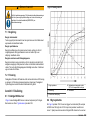
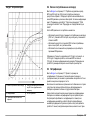
6.1 Typische Kurven
Informationen zu speziellen Vorgehensweisen finden Sie in der
erweiterten Version des Handbuchs.
Abbildung 3 zeigt typische Kurven während eines 10-tägigen
Testzeitraums. Eine Darstellung fehlerhafter Kurven finden Sie in
Abbildung 4 auf Seite 22.
Abbildung 3 Typische Kurven
1 Typisch mit Substratabweichung 3 Typisch mit Zeitversatz
2 Typisch
Deutsch 19

6.2 Herunterladen der Testergebnisse
Übertragung der Ergebnisse auf einen PC
2
:
1. Wählen Sie PROGRAMS > ACCESSORIES >
COMMUNICATIONS > HYPERTERMINAL (PROGRAMME >
ZUBEHÖR > KOMMUNIKATION > HYPERTERMINAL).
2. Geben Sie im Feld „Connection Description“ (Beschreibung der
Verbindung) einen Namen für die Verbindung ein und wählen ein
Symbol für die Darstellung der Verbindung aus. Klicken Sie auf OK.
3. Verwenden Sie im Feld mit der Bezeichnung „Connect To“
(Verbinden mit) das Dropdown Menü zur Wahl des COM-Ports, mit
dem das Gerät verbunden ist. Klicken Sie auf OK.
4. Konfigurieren Sie die Anschlusseinstellungen wie folgt: „BPS“ (Bits
pro Sekunde) = 9600, „Data Bits“ (Datenbits) = 8, „Parity“ (Parität) =
Keine, „Stop Bits“ (Stoppbits) = 1, „Flow Control“ (Flusssteuerung) =
Kein.
5. Klicken Sie auf OK. Die Verbindungsanzeige leuchtet.
6. Wählen Sie TRANSFER > CAPTURE TEXT (ÜBERTRAGUNG >
TEXT AUFZEICHNEN).
7. Klicken Sie im Feld „Capture Text“ (Text aufzeichnen) auf START
(STARTEN).
8. Schalten Sie das Gerät ein. Drücken Sie die Taste für den Kanal,
dessen Daten heruntergeladen werden sollen.
9. Geben Sie „GA“ in das HyperTerminal-Fenster ein und drücken dann
ENTER. Die Übertragung ist abgeschlossen, wenn die
Bildschirmanzeige keine neuen Daten mehr hinzufügt.
10. Wählen Sie TRANSFER > CAPTURE TEXT > STOP
(ÜBERTRAGUNG > TEXT AUFZEICHNEN > STOP).
11. Wählen Sie CALL > DISCONNECT (ANRUFEN > TRENNEN). Die
Anzeige für die getrennte Verbindung leuchtet.
12. Zum Beenden der HyperTerminal-Sitzung wählen Sie FILE > EXIT
(DATEI > BEENDEN).
6.3 Importieren von Daten
Importieren der Daten aus der erfassten Textdatei:
1. Öffnen Sie eine neue oder vorhandene Tabellenkalkulation. Wählen
Sie DATA > IMPORT EXTERNAL DATA > IMPORT DATA
(DATEN > EXTERNE DATEN IMPORTIEREN > DATEN
IMPORTIEREN).
2. Wählen Sie die mit HyperTerminal erfasste Textdatei aus. Klicken
Sie aufIMPORT (IMPORTIEREN).
3. Wählen Sie im Textimport-Assistent die Option „Delimited“ als
Dateiart, die Startreihe in der Kalkulationstabelle und „Windows
(ANSI)“ als Datenquelle. Klicken Sie auf NEXT (WEITER).
4. Aktivieren Sie die Kontrollkästchen für „Space delimiter“
(Trennzeichen) und „Treat consecutive delimiters as one“
(Aufeinanderfolgende Trennzeichen als eins behandeln). Klicken Sie
auf NEXT (WEITER).
5. Wählen Sie „General“ (Allgemein) als Datenformat der Spalte und
klicken abschließend auf Finish (Fertig stellen).
6. Wählen Sie im Feld „Import Data“ (Daten importieren) die Option
„Existing Worksheet“ (Vorhandenes Arbeitsblatt) aus. Wählen Sie die
Startzelle und klicken dann auf OK. Die Daten werden im Arbeitsblatt
angezeigt.
6.4 Datenformat
Das Beispiel zeigt Kanalnummer, Startdatum, Startzeit und das Format
der heruntergeladenen Daten. BSB-Werte in mg/l folgen. Es werden nur
die ersten Datenpunkte, mit maximal 360 gleichen Abstandspunkten,
gezeigt. Jede Zeile endet mit einem Zeilenumbruch und einem
Zeilenvorschub. Das Ende der Datenübertragung wird durch eine
Meldung (z. B. „Testlauf fertig gestellt“) und ein Dollarsymbol ($)
angezeigt.
Wenn bei Testbeginn kleine negative BSB-Werte zu sehen sind, lesen
Sie bitte unter Fehlerbehebung auf Seite 22 weiter.
Beispiel des Datenformats
2
Installiert auf Windows XP oder älter. Bei neueren Windows-Versionen ist die Installation einer Terminalsoftware notwendig.
20 Deutsch
Sayfa yükleniyor...
Sayfa yükleniyor...
Sayfa yükleniyor...
Sayfa yükleniyor...
Sayfa yükleniyor...
Sayfa yükleniyor...
Sayfa yükleniyor...
Sayfa yükleniyor...
Sayfa yükleniyor...
Sayfa yükleniyor...
Sayfa yükleniyor...
Sayfa yükleniyor...
Sayfa yükleniyor...
Sayfa yükleniyor...
Sayfa yükleniyor...
Sayfa yükleniyor...
Sayfa yükleniyor...
Sayfa yükleniyor...
Sayfa yükleniyor...
Sayfa yükleniyor...
Sayfa yükleniyor...
Sayfa yükleniyor...
Sayfa yükleniyor...
Sayfa yükleniyor...
Sayfa yükleniyor...
Sayfa yükleniyor...
Sayfa yükleniyor...
Sayfa yükleniyor...
Sayfa yükleniyor...
Sayfa yükleniyor...
Sayfa yükleniyor...
Sayfa yükleniyor...
Sayfa yükleniyor...
Sayfa yükleniyor...
Sayfa yükleniyor...
Sayfa yükleniyor...
Sayfa yükleniyor...
Sayfa yükleniyor...
Sayfa yükleniyor...
Sayfa yükleniyor...
Sayfa yükleniyor...
Sayfa yükleniyor...
Sayfa yükleniyor...
Sayfa yükleniyor...
Sayfa yükleniyor...
Sayfa yükleniyor...
Sayfa yükleniyor...
Sayfa yükleniyor...
Sayfa yükleniyor...
Sayfa yükleniyor...
Sayfa yükleniyor...
Sayfa yükleniyor...
Sayfa yükleniyor...
Sayfa yükleniyor...
Sayfa yükleniyor...
Sayfa yükleniyor...
Sayfa yükleniyor...
Sayfa yükleniyor...
Sayfa yükleniyor...
Sayfa yükleniyor...
Sayfa yükleniyor...
Sayfa yükleniyor...
Sayfa yükleniyor...
Sayfa yükleniyor...
Sayfa yükleniyor...
Sayfa yükleniyor...
Sayfa yükleniyor...
Sayfa yükleniyor...
Sayfa yükleniyor...
Sayfa yükleniyor...
Sayfa yükleniyor...
Sayfa yükleniyor...
Sayfa yükleniyor...
Sayfa yükleniyor...
Sayfa yükleniyor...
Sayfa yükleniyor...
Sayfa yükleniyor...
Sayfa yükleniyor...
Sayfa yükleniyor...
Sayfa yükleniyor...
Sayfa yükleniyor...
Sayfa yükleniyor...
Sayfa yükleniyor...
Sayfa yükleniyor...
Sayfa yükleniyor...
Sayfa yükleniyor...
Sayfa yükleniyor...
Sayfa yükleniyor...
Sayfa yükleniyor...
Sayfa yükleniyor...
Sayfa yükleniyor...
Sayfa yükleniyor...
Sayfa yükleniyor...
Sayfa yükleniyor...
Sayfa yükleniyor...
Sayfa yükleniyor...
Sayfa yükleniyor...
Sayfa yükleniyor...
Sayfa yükleniyor...
Sayfa yükleniyor...
Sayfa yükleniyor...
Sayfa yükleniyor...
Sayfa yükleniyor...
Sayfa yükleniyor...
Sayfa yükleniyor...
Sayfa yükleniyor...
Sayfa yükleniyor...
Sayfa yükleniyor...
Sayfa yükleniyor...
Sayfa yükleniyor...
Sayfa yükleniyor...
Sayfa yükleniyor...
Sayfa yükleniyor...
Sayfa yükleniyor...
Sayfa yükleniyor...
Sayfa yükleniyor...
Sayfa yükleniyor...
Sayfa yükleniyor...
Sayfa yükleniyor...
Sayfa yükleniyor...
Sayfa yükleniyor...
Sayfa yükleniyor...
Sayfa yükleniyor...
Sayfa yükleniyor...
Sayfa yükleniyor...
Sayfa yükleniyor...
Sayfa yükleniyor...
Sayfa yükleniyor...
Sayfa yükleniyor...
Sayfa yükleniyor...
Sayfa yükleniyor...
Sayfa yükleniyor...
Sayfa yükleniyor...
Sayfa yükleniyor...
Sayfa yükleniyor...
Sayfa yükleniyor...
Sayfa yükleniyor...
Sayfa yükleniyor...
Sayfa yükleniyor...
Sayfa yükleniyor...
Sayfa yükleniyor...
Sayfa yükleniyor...
Sayfa yükleniyor...
Sayfa yükleniyor...
Sayfa yükleniyor...
Sayfa yükleniyor...
Sayfa yükleniyor...
Sayfa yükleniyor...
-
 1
1
-
 2
2
-
 3
3
-
 4
4
-
 5
5
-
 6
6
-
 7
7
-
 8
8
-
 9
9
-
 10
10
-
 11
11
-
 12
12
-
 13
13
-
 14
14
-
 15
15
-
 16
16
-
 17
17
-
 18
18
-
 19
19
-
 20
20
-
 21
21
-
 22
22
-
 23
23
-
 24
24
-
 25
25
-
 26
26
-
 27
27
-
 28
28
-
 29
29
-
 30
30
-
 31
31
-
 32
32
-
 33
33
-
 34
34
-
 35
35
-
 36
36
-
 37
37
-
 38
38
-
 39
39
-
 40
40
-
 41
41
-
 42
42
-
 43
43
-
 44
44
-
 45
45
-
 46
46
-
 47
47
-
 48
48
-
 49
49
-
 50
50
-
 51
51
-
 52
52
-
 53
53
-
 54
54
-
 55
55
-
 56
56
-
 57
57
-
 58
58
-
 59
59
-
 60
60
-
 61
61
-
 62
62
-
 63
63
-
 64
64
-
 65
65
-
 66
66
-
 67
67
-
 68
68
-
 69
69
-
 70
70
-
 71
71
-
 72
72
-
 73
73
-
 74
74
-
 75
75
-
 76
76
-
 77
77
-
 78
78
-
 79
79
-
 80
80
-
 81
81
-
 82
82
-
 83
83
-
 84
84
-
 85
85
-
 86
86
-
 87
87
-
 88
88
-
 89
89
-
 90
90
-
 91
91
-
 92
92
-
 93
93
-
 94
94
-
 95
95
-
 96
96
-
 97
97
-
 98
98
-
 99
99
-
 100
100
-
 101
101
-
 102
102
-
 103
103
-
 104
104
-
 105
105
-
 106
106
-
 107
107
-
 108
108
-
 109
109
-
 110
110
-
 111
111
-
 112
112
-
 113
113
-
 114
114
-
 115
115
-
 116
116
-
 117
117
-
 118
118
-
 119
119
-
 120
120
-
 121
121
-
 122
122
-
 123
123
-
 124
124
-
 125
125
-
 126
126
-
 127
127
-
 128
128
-
 129
129
-
 130
130
-
 131
131
-
 132
132
-
 133
133
-
 134
134
-
 135
135
-
 136
136
-
 137
137
-
 138
138
-
 139
139
-
 140
140
-
 141
141
-
 142
142
-
 143
143
-
 144
144
-
 145
145
-
 146
146
-
 147
147
-
 148
148
-
 149
149
-
 150
150
-
 151
151
-
 152
152
-
 153
153
-
 154
154
-
 155
155
-
 156
156
-
 157
157
-
 158
158
-
 159
159
-
 160
160
-
 161
161
-
 162
162
-
 163
163
-
 164
164
-
 165
165
-
 166
166
-
 167
167
-
 168
168


diğer dillerde
- español: Hach BODTrak II
- français: Hach BODTrak II
- italiano: Hach BODTrak II
- svenska: Hach BODTrak II
- polski: Hach BODTrak II
- Deutsch: Hach BODTrak II
- português: Hach BODTrak II
- English: Hach BODTrak II
- Nederlands: Hach BODTrak II
- română: Hach BODTrak II
İlgili makaleler
-
Hach SC200 Quick Manual
-
 Hach AS950 Basic Operations
-
 Hach ORBISPHERE K-M1100 Basic User Manual
-
 Hach ORBISPHERE 510 Basic User Manual
-
 Hach BOD Direct plus Basic User Manual
-
 Hach Lange ORBISPHERE 3100 Basic User Manual
-
Hach CL17sc Kullanım kılavuzu
-
 Hach Lange ORBISPHERE 3100 Basic User Manual
-
 Hach 51 Series Kullanım kılavuzu
-
 Hach AS950 AWRS Basic Installation And Maintenance


