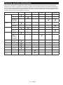
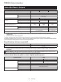
Makita DUC254 Kullanım kılavuzu
- Kategori
- Akülü motorlu testereler
- Tip
- Kullanım kılavuzu
Bu kılavuz aynı zamanda aşağıdakiler için de uygundur:

DUC204
DUC254
DUC254C
EN Cordless Chain Saw INSTRUCTION MANUAL 7
FR Tronçonneuse sans Fil MANUEL D’INSTRUCTIONS 19
DE Akku-Kettensäge BETRIEBSANLEITUNG 33
IT Motosega a batteria ISTRUZIONI PER L’USO 47
NL Accukettingzaag GEBRUIKSAANWIJZING 62
ES Electrosierra Inalámbrica MANUAL DE
INSTRUCCIONES 76
PT Motosserra a Bateria MANUAL DE INSTRUÇÕES 90
DA Akku-kædesav BRUGSANVISNING 103
EL 116
TR KULLANMA KILAVUZU 131

2
Fig.1
12 34
5
6
12
13
14
7
8
10
9
11
16
17
18
15
Fig.2
1
2
3
Fig.3
1
2
Fig.4

3
1
2
Fig.5
1
2
Fig.6
1
23
23
Fig.7
1
Fig.8
1
2
Fig.9
2
3
4
1
Fig.10
1
Fig.11

4
12
Fig.12
1
Fig.13
1
2
3
Fig.14
1
Fig.15
12
Fig.16
1
2
Fig.17
Fig.18
Fig.19

5
Fig.20
1
2
Fig.21
Fig.22
1
2
Fig.23
22
11
31
Fig.24
30
30
55 55
Fig.25
1
2
Fig.26
30
1/5
1
Fig.27

6
Fig.28
Fig.29
Fig.30
1
2
Fig.31
1
2
Fig.32
1
2
Fig.33

7ENGLISH
ENGLISH (Original instructions)
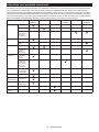
SPECIFICATIONS
Model: DUC204 DUC254 DUC254C
Overall length (without guide bar) 256 mm
Rated voltage D.C. 18 V
Net weight *1 2.0 kg
*2 2.8 - 3.3 kg
Standard guide bar length 200 mm 250 mm
Recommended guide bar
length
with 90PX 200 - 250 mm -
with 91PX -250 mm -
with 25AP -250 mm
Applicable saw chain type
(refer to the table below)
90PX 90PX
91PX
25AP
Standard sprocket Number of teeth 6 9
Pitch
Chain speed 0 - 24 m/s
(0 - 1,440 m/min)
0 - 22.5 m/s
(0 - 1,350 m/min)
Chain oil tank volume 140 cm3
without notice.
*1: Weight, without the saw chain, guide bar, guide bar cover, oil and battery cartridge(s).
depending on the attachment(s), including the battery cartridge(s).
Applicable battery cartridge and charger
Battery cartridge BL1815N / BL1820B / BL1830B / BL1840B / BL1850B / BL1860B
Charger DC18RC / DC18RD / DC18RE / DC18SD / DC18SE / DC18SF /
DC18SH
• Some of the battery cartridges and chargers listed above may not be available depending on your region of
residence.
WARNING: Only use the battery cartridges and chargers listed above. Use of any other battery cartridges
Saw chain, guide bar, and sprocket combination
Saw chain type 90PX
Number of drive links 33 40
Guide bar Guide bar length 200 mm 250 mm
Cutting length 171 mm 235 mm
Pitch
Gauge 1.1 mm
Type Sprocket nose bar
Sprocket Number of teeth 6
Pitch

8ENGLISH
Saw chain type 91PX
Number of drive links 40
Guide bar Guide bar length 250 mm
Cutting length 235 mm
Pitch
Gauge 1.3 mm
Type Sprocket nose bar
Sprocket Number of teeth 6
Pitch
Saw chain type 25AP
Number of drive links 60
Guide bar Guide bar length 250 mm
Cutting length 250 mm
Pitch
Gauge 1.3 mm
Type Carving bar
Sprocket Number of teeth 9
Pitch
NOTICE: When using 25AP saw chain, use with Sprocket 9 (optional accessory).
WARNING:
result.
Symbols
The followings show the symbols which may be used
for the equipment. Be sure that you understand their
meaning before use.
Read instruction manual.
Wear safety glasses.
Wear ear protection.
Wear a helmet, goggles and ear protection.
Use appropriate protection for foot-leg and
hand-arm.
This saw is to be used by properly trained
operators only.
Do not expose to moisture.
Maximum permissible cut length
Always use two hands when operating the
chain saw.
Direction of chain travel
Ni-MH
Li-ion
Only for EU countries
Due to the presence of hazardous com-
ponents in the equipment, waste electrical
and electronic equipment, accumulators
and batteries may have a negative impact
on the environment and human health.
Do not dispose of electrical and electronic
appliances or batteries with household
waste!
In accordance with the European Directive
on waste electrical and electronic equip-
ment and on accumulators and batteries
and waste accumulators and batteries,
as well as their adaptation to national law,
waste electrical equipment, batteries and
accumulators should be stored separately
and delivered to a separate collection point
for municipal waste, operating in accor-
dance with the regulations on environmen-
tal protection.
This is indicated by the symbol of the
crossed-out wheeled bin placed on the
equipment.
Guaranteed sound power level according
to EU Outdoor Noise Directive.
Sound power level according to Australia
NSW Noise Control Regulation.
Intended use
The tool is intended for cutting branches and pruning
trees. It is also suitable for tree service.

9ENGLISH
Noise
The typical A-weighted noise level determined accord-
ing to EN62841-1 and EN ISO 11681-2 as applicable:
Model DUC204
Sound pressure level (LpA) : 93 dB(A)
Sound power level (LWA) : 101 dB (A)
Uncertainty (K) : 3 dB(A)
Model DUC254
Sound pressure level (LpA) : 93 dB(A)
Sound power level (LWA) : 101 dB (A)
Uncertainty (K) : 3 dB(A)
Model DUC254C
Sound pressure level (LpA) : 93 dB(A)
Sound power level (LWA) : 101 dB (A)
Uncertainty (K) : 3 dB(A)
NOTE: The declared noise emission value(s) has
been measured in accordance with a standard test
method and may be used for comparing one tool with
another.
NOTE: The declared noise emission value(s)
may also be used in a preliminary assessment of
exposure.
WARNING: Wear ear protection.
WARNING: The noise emission during actual
value(s) depending on the ways in which the
tool is used especially what kind of workpiece is
processed.
WARNING: Be sure to identify safety mea-
sures to protect the operator that are based on an
estimation of exposure in the actual conditions of
use (taking account of all parts of the operating
cycle such as the times when the tool is switched
trigger time).
Vibration
The vibration total value (tri-axial vector sum) deter-
mined according to EN62841-1 and EN ISO 11681-2 as
applicable:
Model DUC204
Work mode: cutting wood
Vibration emission (ah,W) : 2.5 m/s2
Uncertainty (K) : 1.5 m/s2
Model DUC254
Work mode: cutting wood
Vibration emission (ah,W) : 2.5 m/s2
Uncertainty (K) : 1.5 m/s2
Model DUC254C
Work mode: cutting wood
Vibration emission (ah,W) : 3.6 m/s2
Uncertainty (K) : 1.5 m/s2
NOTE: The declared vibration total value(s) has been
measured in accordance with a standard test method
and may be used for comparing one tool with another.
NOTE: The declared vibration total value(s) may also
be used in a preliminary assessment of exposure.
WARNING: The vibration emission during
declared value(s) depending on the ways in which
the tool is used especially what kind of workpiece
is processed.
WARNING: Be sure to identify safety mea-
sures to protect the operator that are based on an
estimation of exposure in the actual conditions of
use (taking account of all parts of the operating
cycle such as the times when the tool is switched
trigger time).
EC Declaration of Conformity
For European countries only
The EC declaration of conformity is included as Annex A
to this instruction manual.
SAFETY WARNINGS
General power tool safety warnings
WARNING: Read all safety warnings, instruc-
with this power tool. Failure to follow all instructions
Save all warnings and instruc-
tions for future reference.
The term "power tool" in the warnings refers to your
mains-operated (corded) power tool or battery-operated
(cordless) power tool.
Cordless Chain saw safety warnings
1. Keep all parts of the body away from the saw
chain when the chain saw is operating. Before
you start the chain saw, make sure the saw
chain is not contacting anything. A moment of
inattention while operating chain saws may cause
entanglement of your clothing or body with the
saw chain.
2. Always hold the chain saw with your right
hand on the top handle and your left hand on
the front handle. Holding the chain saw with a
3. Hold the power tool by insulated gripping
surfaces only, because the saw chain may con-
tact hidden wiring. Saw chains contacting a "live"
wire may make exposed metal parts of the power
tool "live" and could give the operator an electric
shock.
4. Wear safety glasses and hearing protection.
Further protective equipment for head, hands,
legs and feet is recommended. Adequate protec-
debris or accidental contact with the saw chain.
5. Always keep proper footing.

10 ENGLISH
6.
When cutting a limb that is under tension be alert
for spring back.
is released the spring loaded limb may strike the
operator and/or throw the chain saw out of control.
7. Use extreme caution when cutting brush and
saplings. The slender material may catch the saw
balance.
8. Carry the chain saw by the front handle with
body. When transporting or storing the chain
Proper
handling of the chain saw will reduce the likelihood
of accidental contact with the moving saw chain.
9. Follow instructions for lubricating, chain ten-
sioning and changing accessories. Improperly
tensioned or lubricated chain may either break or
increase the chance for kickback.
10. Keep handles dry, clean, and free from oil and
grease. Greasy, oily handles are slippery causing
loss of control.
11. Cut wood only. Do not use chain saw for pur-
poses not intended. For example: do not use
chain saw for cutting plastic, masonry or non-
wood building materials. Use of the chain saw for
hazardous situation.
12. Causes and operator prevention of kickback:
Kickback may occur when the nose or tip of the
closes in and pinches the saw chain in the cut.
Tip contact in some cases may cause a sudden
reverse reaction, kicking the guide bar up and
back towards the operator. Pinching the saw chain
along the top of the guide bar may push the guide
bar rapidly back towards the operator. Either of
these reactions may cause you to lose control of
the saw which could result in serious personal
devices built into your saw. As a chain saw user,
you should take several steps to keep your cutting
Kickback is the result of tool misuse and/or incor-
rect operating procedures or conditions and can be
avoided by taking proper precautions as given below:
encircling the chain saw handles, with both
hands on the saw and position your body
and arm to allow you to resist kickback
forces. Kickback forces can be controlled by
the operator, if proper precautions are taken.
Do not let go of the chain saw.
Fig.1
• Do not overreach and do not cut above
shoulder height. This helps prevent unin-
tended tip contact and enables better control
of the chain saw in unexpected situations.
• Only use replacement bars and chains spec-
-
ment bars and chains may cause chain
breakage and/or kickback.
• Follow the manufacturer’s sharpening and
maintenance instructions for the saw chain.
Decreasing the depth gauge height can lead
to increased kickback.
13. Before starting work, check that the chain
saw is in proper working order and that its
condition complies with the safety regulations.
Check in particular that:
• The chain brake is working properly;
• The run-down brake is working properly;
correctly;
• The chain has been sharpened and ten-
sioned in accordance with the regulations.
14. Do not start the chain saw with the chain cover
being installed on it. Starting the chain saw with
the chain cover being installed on it may cause
the chain cover to thrown out forward resulting in
operator.
Additional Safety Warnings:
1. When using the tool with battery adapter,
be careful not to trip over the cord during
operation.
2. When using the tool with battery adapter, keep
the cord away from obstacles such as a work-
piece and branches during operation. The cord
warnings
1. This chain saw is designed especially for tree
care and surgery. The chain saw is intended
to be used by properly trained persons only.
Observe all instructions, procedures and rec-
ommendations from the relevant professional
organization. Otherwise fatal accidents may
occur. It is recommend that always using a
rising platform (cherry picker, lift) for sawing
in trees. Rappelling techniques are extremely
dangerous and require special training. The
operators must be trained to become familiar
with safety equipment usage and climbing
techniques. Always use the appropriate belts,
ropes and carabiners when working in trees.
Always use restraining equipment for both the
operator and the saw.
2. Perform cleaning and maintenance before
storage in accordance with the instruction
manual.
3. Ensure safe positioning of the chain saw
during car transportation to avoid fuel or chain
oil leakage, damage to the tool and personal
injury.
4. Regularly check the functionality of chain
brake.
5.
6. National regulation may restrict the use of the
chain saw.
7. If the equipment gets heavy impact or fall,
check the condition before continuing work.
Check the controls and safety devices for mal-
function. If there is any damage or doubt, ask
our authorized service center for the inspec-
tion and repair.
8. Always activate the chain brake before starting
the chain saw.

11 ENGLISH
9.
(skid movement) or bouncing of the saw when
starting a cut.
10. At the end of the cut, be careful to keep your
balance due to the “drop”.
11. Take into account the direction and speed of
the wind. Avoid sawdust and chain oil mist.
Protective equipment
1. In order to avoid head, eye, hand or foot
injuries as well as to protect your hearing the
following protective equipment must be used
during operation of the chain saw:
—
The kind of clothing should be appropriate, i. e.
become entangled with bushes or shrubs. If
you have long hair, always wear a hairnet!
— It is necessary to wear a protective helmet
whenever working with the chain saw. The
protective helmet is to be checked in regu-
lar intervals for damage and is to be replaced
after 5 years at the latest. Use only approved
protective helmets.
— The face shield of the protective helmet (or
the goggles) protects against sawdust and
wood chips. During operation of the chain
saw always wear a goggle or a face shield to
— Wear adequate noise protection equip-
ment
— The protective jacket consists of 22 layers
of nylon and protects the operator against
cuts. It is always to be worn when working
from elevated platforms (cherry pickers,
lifts), from platforms mounted on ladders or
when climbing with ropes.
— The protective brace and bib overall is
made of a nylon fabric with 22 layers and
protects against cuts. We strongly recom-
mend its use.
—
Protective gloves made of thick leather are part
of the prescribed equipment and must always be
worn during operation of the chain saw.
— During operation of the chain saw safety
shoes or safety boots
sole, steel toe caps and protection for the
leg must always to be worn. Safety shoes
equipped with a protective layer provide
protection against cuts and ensure a secure
footing. For working in trees the safety boots
must be suitable for climbing techniques.
Vibration
1. Individuals with poor circulation who are exposed
blood vessels or the nervous system. Vibration
may cause the following symptoms to occur in the
-
ness), tingling, pain, stabbing sensation, alteration
of skin colour or of the skin. If any of these symp-
toms occur, see a physician! To reduce the risk
during operation and well maintain the equipment
and accessories.
SAVE THESE INSTRUCTIONS.
WARNING: DO NOT let comfort or familiarity
with product (gained from repeated use) replace
strict adherence to safety rules for the subject
product. MISUSE or failure to follow the safety
rules stated in this instruction manual may cause
serious personal injury.
Important safety instructions for
battery cartridge
1. Before using battery cartridge, read all instruc-
tions and cautionary markings on (1) battery
charger, (2) battery, and (3) product using
battery.
2. Do not disassemble or tamper with the battery
cartridge.
or explosion.
3. If operating time has become excessively
shorter, stop operating immediately. It may
result in a risk of overheating, possible burns
and even an explosion.
4. If electrolyte gets into your eyes, rinse them
out with clear water and seek medical atten-
tion right away. It may result in loss of your
eyesight.
5. Do not short the battery cartridge:
(1) Do not touch the terminals with any con-
ductive material.
(2) Avoid storing battery cartridge in a con-
tainer with other metal objects such as
nails, coins, etc.
(3) Do not expose battery cartridge to water
or rain.
A battery short can cause a large current
breakdown.
6. Do not store and use the tool and battery car-
tridge in locations where the temperature may
reach or exceed 50 °C (122 °F).
7. Do not incinerate the battery cartridge even if
it is severely damaged or is completely worn
8. Do not nail, cut, crush, throw, drop the battery
cartridge, or hit against a hard object to the
battery cartridge. Such conduct may result in a
9. Do not use a damaged battery.
10. The contained lithium-ion batteries are subject
to the Dangerous Goods Legislation require-
ments.
For commercial transports e.g. by third parties,
forwarding agents, special requirement on pack-
aging and labeling must be observed.
For preparation of the item being shipped, consult-
ing an expert for hazardous material is required.
Please also observe possibly more detailed
national regulations.
battery in such a manner that it cannot move
around in the packaging.
11. When disposing the battery cartridge, remove
it from the tool and dispose of it in a safe
place. Follow your local regulations relating to
disposal of battery.

12 ENGLISH
12. Use the batteries only with the products
Installing the batteries to
-
sive heat, explosion, or leak of electrolyte.
13. If the tool is not used for a long period of time,
the battery must be removed from the tool.
14. During and after use, the battery cartridge may
take on heat which can cause burns or low
temperature burns. Pay attention to the han-
dling of hot battery cartridges.
15. Do not touch the terminal of the tool imme-
diately after use as it may get hot enough to
cause burns.
16. Do not allow chips, dust, or soil stuck into the
terminals, holes, and grooves of the battery
cartridge.
burst and malfunction of the tool or battery car-
17. Unless the tool supports the use near
high-voltage electrical power lines, do not use
the battery cartridge near high-voltage electri-
cal power lines. It may result in a malfunction or
breakdown of the tool or battery cartridge.
18. Keep the battery away from children.
SAVE THESE INSTRUCTIONS.
CAUTION: Only use genuine Makita batteries.
Use of non-genuine Makita batteries, or batteries that
have been altered, may result in the battery bursting
also void the Makita warranty for the Makita tool and
charger.
Tips for maintaining maximum
battery life
1. Charge the battery cartridge before completely
discharged. Always stop tool operation and
charge the battery cartridge when you notice
less tool power.
2. Never recharge a fully charged battery car-
tridge. Overcharging shortens the battery
service life.
3. Charge the battery cartridge with room tem-
perature at 10 °C - 40 °C (50 °F - 104 °F). Let
a hot battery cartridge cool down before
charging it.
4. When not using the battery cartridge, remove
it from the tool or the charger.
5. Charge the battery cartridge if you do not use
it for a long period (more than six months).
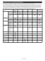
PARTS DESCRIPTION
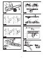
Fig.2
1Switch trigger 2Top handle 3
4Front hand guard 5Guide bar 6Saw chain
7Chain catcher 8Retaining nut 9
10 Chip guide 11 Battery cartridge 12 Main power lamp
13 Main power switch 14 15 Carabiner
16 Front handle 17 Oil tank cap 18 Guide bar cover
FUNCTIONAL
DESCRIPTION
CAUTION: Always be sure that the tool is
before adjusting or checking function on the tool.
Installing or removing battery
cartridge
CAUTION:
installing or removing of the battery cartridge.
CAUTION: Hold the tool and the battery car-
cartridge. Failure to hold the tool and the battery
and result in damage to the tool and battery cartridge
Fig.3: 1. Red indicator 2. Button 3. Battery cartridge
To remove the battery cartridge, slide it from the tool
while sliding the button on the front of the cartridge.
To install the battery cartridge, align the tongue on the
battery cartridge with the groove in the housing and slip
it into place. Insert it all the way until it locks in place
with a little click. If you can see the red indicator as
CAUTION: Always install the battery cartridge
fully until the red indicator cannot be seen. If not,
you or someone around you.
CAUTION: Do not install the battery cartridge
forcibly. If the cartridge does not slide in easily, it is
not being inserted correctly.

13 ENGLISH
Indicating the remaining battery capacity
Only for battery cartridges with the indicator
Fig.4: 1. Indicator lamps 2. Check button
Press the check button on the battery cartridge to indi-
cate the remaining battery capacity. The indicator lamps
light up for a few seconds.
Indicator lamps Remaining
capacity
Lighted Blinking
75% to 100%
50% to 75%
25% to 50%
0% to 25%
Charge the
battery.
The battery
may have
malfunctioned.
NOTE: Depending on the conditions of use and the
from the actual capacity.
NOTE:
the battery protection system works.
Tool / battery protection system
The tool is equipped with a tool/battery protection sys-
motor to extend tool and battery life. The tool will auto-
matically stop during operation if the tool or battery is
placed under one of the following conditions:
Overload protection
When the battery is operated in a manner that causes it to
draw an abnormally high current, the tool automatically stops
and the main power lamp blinks in green. In this situation,
to become overloaded. Then turn the tool on to restart.
Overheat protection
When the tool or battery is overheated, the tool stops automat-
ically and the main power lamp lights up in red. In this case, let
the tool and battery cool before turning the tool on again.
NOTE: In high temperature environment, the over-
heat protection likely to work and the tool stops
automatically.
Overdischarge protection
When the battery capacity is not enough, the tool stops
automatically and the main power lamp blinks in red. In
this case, remove the battery from the tool and charge
the battery.
Main power switch
WARNING:
switch when not in use.
To turn on the tool, press the main power switch until
press the main power switch again.
Fig.5: 1. Main power lamp 2. Main power switch
NOTE: The main power lamp blinks in green if the
switch trigger is pulled under unoperatable conditions.
The lamp blinks in one of the following conditions.
• When you turn on the main power switch while
trigger.
• When you pull the switch trigger while the chain
brake is applied.
• When you release the chain brake while holding
trigger.
NOTE:
To avoid unintentional start up, the main power switch
will automatically shut down when the switch trigger
is not pulled for a certain period after the main power
switch is turned on.
You can use the tool in the Torque Boost mode for
cutting thick branches or hard branches. To use the tool
press the main power switch for a few seconds until the
main power lamp lights up in yellow.
NOTE: You can use the tool in the Torque Boost
mode up to 60 seconds. Depending on the usage
conditions, this mode shifts to the normal mode in
less than 60 seconds.
NOTE: If the main power lamp blinks in yellow when
you press the main power switch for a few seconds,
the Torque Boost mode is not available. In this case,
follow the steps below.
• The Torque Boost mode is not available right
after the cutting operation. Wait for more than 10
seconds, and then press the main power switch
again.
• If you use the Torque Boost mode several times,
the use of the Torque Boost mode is restricted to
protect the battery. If the Torque Boost mode is
not available after waiting for more than 10 sec-
onds, replace the battery cartridge with a fully
charged one, or recharge the battery cartridge.
NOTE: If the main power lamp lights up in red or
blinks in red or green, refer to the instructions for tool/
battery protection system.
NOTE: The Torque Boost mode cannot be used when
the battery cartridge BL1815N, BL1820, or BL1820B
is installed.

14 ENGLISH
Switch action
WARNING: For your safety, this tool is
tool from unintended starting. NEVER use the tool
if it runs when you simply pull the switch trigger
tool to our authorized service center for proper
repairs BEFORE further usage.
WARNING: NEVER tape down or defeat pur-
CAUTION: Before installing the battery car-
tridge into the tool, always check to see that the
switch trigger actuates properly and returns to
the "OFF" position when released.
NOTICE: Do not pull the switch trigger hard with-
switch breakage.
To prevent the switch trigger from being accidentally
The tool speed increases by increasing pressure on the
switch trigger. Release the switch trigger to stop.
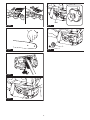
Fig.6: 1. Switch trigger 2.
Checking the chain brake
CAUTION: Hold the chain saw with both
hands when switching it on. Hold the top handle
with your right hand, the front handle with your
left. The bar and the chain must not be in contact
with any object.
CAUTION: Should the saw chain not stop
immediately when this test is performed, the
saw may not be used under any circumstances.
Consult our authorized service center.
1. -
ger. The saw chain starts immediately.
2. Push the front hand guard forwards with the back
of your hand. Make sure that the chain saw comes to an
immediate standstill.
Fig.7: 1. Front hand guard 2. Unlocked position
3. Locked position
Checking the run-down brake
CAUTION: If the saw chain does not stop
within two seconds in this test, stop using the
chain saw and consult our authorized service
center.
Run the chain saw then release the switch trigger completely.
The saw chain must come to a standstill within two seconds.
Adjusting the chain lubrication
screw using the universal wrench. The amount of oil
Fig.8: 1.
Carabiner (rope attachment point)
You can hang the tool by attaching the rope to the cara-
biner. Pull up the carabiner, and then tie it with the rope.
Electronic function
The tool is equipped with the electronic functions for easy operation.
• Soft start
The soft-start function minimizes start-up shock,
and makes the tool start smoothly.
ASSEMBLY
CAUTION: Always be sure that the tool is
before carrying out any work on the tool.
CAUTION: Do not touch the saw chain with
bare hands. Always wear gloves when handling
the saw chain.
Removing or installing saw chain
CAUTION:
The saw chain and the guide bar are
still hot just after the operation. Let them cool down
enough before carrying out any work on the tool.
CAUTION: Carry out the procedure of install-
ing or removing saw chain in a clean place free
from sawdust and the like.
To install the saw chain, perform the following steps:
1.
Check the direction of the saw chain. Match the direction
of the saw chain with that of the mark on the chain saw body.
2.
Fit one end of the saw chain on the top of the guide bar.
3. Fit the other end of the saw chain around the
sprocket, then attach the guide bar to the chain saw
body, aligning the hole on the guide bar with the pin on
the chain saw body.
Fig.9: 1. Sprocket 2. Hole
4. Insert the protrusion on the sprocket cover to the
chain saw body, and then close the cover so that the
bolt and pins on the chain saw body meet their counter-
parts on the cover.
Fig.10: 1. Protrusion 2. Sprocket cover 3. Bolt
4. Pin
5. Tighten the retaining nut to secure the sprocket
procedure.)
Fig.11: 1. Retaining nut
To remove the saw chain, perform the following steps:
1.
Release the chain brake by pulling the front hand guard.
2. -
ing nut.
Fig.12: 1.2. Retaining nut
3. Remove the sprocket cover then remove the saw
chain and guide bar from the chain saw body.

15 ENGLISH
Adjusting saw chain tension
CAUTION: Do not tighten the saw chain too
much. Excessively high tension of saw chain may
cause breakage of saw chain and wear of the guide
bar.
CAUTION: A chain which is too loose can
accident.
The saw chain may become loose after many hours
of use. From time to time check the saw chain tension
before use.
1. Release the chain brake by pulling the front hand
guard.
2. Loosen the retaining nut a bit to loosen the
sprocket cover lightly.
Fig.13: 1. Retaining nut
3.
to tighten, turn it counterclockwise to loosen.
For chain blade 90PX and 91PX:
Tighten the saw chain until the lower side of the saw
Fig.14: 1. Guide bar 2. Saw chain 3.-
ing screw
For chain blade 25AP:
Tighten the saw chain so that the gap between the cen-
ter of the lower side of the guide bar and the saw chain
becomes approximately 1 mm to 2 mm.
4. Keep holding the guide bar lightly and tighten the
sprocket cover.
For chain blade 90PX and 91PX:
Make sure that the saw chain does not loose at the
lower side.
For chain blade 25AP:
Make sure that the gap between the center of the lower
side of the guide bar and the saw chain is approximately
1 mm to 2 mm.
5. Tighten the retaining nut to secure the sprocket
cover.
Fig.15: 1. Retaining nut
side of the bar.
Spike bumper
Optional accessory
When cutting thick branches, using the spike bumper is
recommended. To install the spike bumper, perform the
following steps:
1. Remove the sprocket cover, saw chain, and guide
bar.
2. Align the holes of the spike bumper with the holes
on the chain saw body, and then tighten the screws
Fig.16: 1. Screw 2. Spike bumper
OPERATION
Lubrication
Saw chain is automatically lubricated when the tool is in
operation. Check the amount of remaining oil in the oil
tank periodically through the oil inspection window.
the tank, make sure that the oil tank cap is tightened securely.
Fig.17: 1. Oil tank cap 2. Oil inspection window
and wait until lubrication on saw chain is adequate.
Fig.18
NOTICE:
-
The oil delivery may otherwise be impaired.
NOTICE:
Use the saw chain oil exclusively for Makita
chain saws or equivalent oil available in the market.
NOTICE: Never use oil including dust and parti-
cles or volatile oil.
NOTICE: When pruning trees, use botanical oil.
Mineral oil may harm trees.
NOTICE: Before the cutting operation, make sure
that the provided oil tank cap is screwed in place.
WORKING WITH THE CHAIN SAW
CAUTION: Keep all parts of the body away
from the saw chain when the motor is operating.
CAUTION:
both hands when the motor is running.
CAUTION: Do not overreach. Keep proper
footing and balance at all times.
NOTICE: Never toss or drop the tool.
NOTICE: Do not cover the vents of the tool.
Pruning trees
Bring the chain saw body into contact with the branch to be cut
before switching on. Otherwise it may cause the guide bar to
Fig.19
If you cannot cut the timber right through with a single stroke:
Apply light pressure to the handle and continue sawing
and draw the chain saw back a little.
Fig.20
Fig.21
branch may close in and pinch the saw chain in the cut.
shallow undercut, the branch may splinter.
Fig.22

16 ENGLISH
Carrying tool
Before carrying the tool, always apply the chain brake
and remove the battery cartridges from the tool. Then
attach the guide bar cover. Also cover the battery car-
tridge with the battery cover.
Fig.23: 1. Guide bar cover 2. Battery cover
MAINTENANCE
CAUTION: Always be sure that the tool is
before attempting to perform inspection or
maintenance.
CAUTION: Always wear gloves when perform-
ing any inspection or maintenance.
NOTICE: Never use gasoline, benzine, thinner,
alcohol or the like. Discoloration, deformation or
cracks may result.
To maintain product SAFETY and RELIABILITY,
be performed by Makita Authorized or Factory Service
Centers, always using Makita replacement parts.
Sharpening the saw chain
Sharpen the saw chain when:
• Mealy sawdust is produced when damp wood is
cut;
when heavy pressure is applied;
• The cutting edge is obviously damaged;
• The saw pulls to the left or right in the wood.
(caused by uneven sharpening of the saw chain or
damage to one side only)
Sharpen the saw chain frequently but a little each time.
routine resharpening. When the saw chain has been
resharpened several times, have it sharpened in our
authorized service center.
Sharpening criteria:
WARNING: An excessive distance between
the cutting edge and depth gauge increases the
risk of kickback.
Fig.24: 1. Cutter length 2. Distance between cutting
edge and depth gauge 3. Minimum cutter
length (3 mm)
lengths prevent the saw chain from running
smoothly and may cause the saw chain to break.
— Do not sharpen the chain when the cutter length
has reached 3 mm or shorter. The chain must be
replaced with new one.
— The chip thickness is determined by the distance
between the depth gauge (round nose) and the
cutting edge.
— The best cutting results are obtained with following
distance between cutting edge and depth gauge.
• Chain blade 90PX : 0.65 mm
• Chain blade 91PX : 0.65 mm
• Chain blade 25AP : 0.65 mm
Fig.25
— The sharpening angle of 30° must be the same on
to run roughly and unevenly, accelerate wear, and
lead to chain breaks.
-
ening angle is kept against the teeth.
• Chain blade 90PX : 55°
• Chain blade 91PX : 55°
• Chain blade 25AP : 55°
saw chains to sharpen the chain. Normal round
follows:
• Chain blade 90PX : 4.5 mm
• Chain blade 91PX : 4.0 mm
• Chain blade 25AP : 4.0 mm
-
stroke.
of this shortest cutter becomes the standard for all
other cutters on the saw chain.
Fig.26: 1. File 2. Saw chain
has markings for the correct sharpening angle of
30° (align the markings parallel to the saw chain)
and limits the depth of penetration (to 4/5 of the
Fig.27: 1. File holder
— After sharpening the chain, check the height of the
depth gauge using the chain gauge tool (optional
accessory).
Fig.28
Cleaning the guide bar
Chips and sawdust will build up in the guide bar groove.
Clean out the chips and sawdust every time when you
sharpen or replace the saw chain.
Fig.29
Cleaning the sprocket cover
Chips and saw dust will accumulate inside of the
sprocket cover. Remove the sprocket cover and saw
chain from the tool then clean the chips and saw dust.
Fig.30

17 ENGLISH
Cleaning the oil discharge hole
Small dust or particles may be built up in the oil dis-
charge hole during operation. These dust or particles
lubrication on the whole saw chain. When a poor chain
oil delivery occurs at the top of guide bar, clean the oil
discharge hole as follows.
1. Remove the sprocket cover and saw chain from
the tool.
2. Remove the small dust or particles using a slotted
screwdriver or the like.
Fig.31: 1. Slotted screwdriver 2. Oil discharge hole
3. Insert the battery cartridge into the tool. Pull the
discharge hole by discharging chain oil.
4. Remove the battery cartridge from the tool.
Reinstall the sprocket cover and saw chain on the tool.
Replacing the sprocket
CAUTION:
A worn sprocket will damage a new
saw chain. Have the sprocket replaced in this case.
Fig.32: 1. Sprocket 2. Areas to be worn out
Fig.33: 1. Locking ring 2. Sprocket
NOTICE: Make sure that the sprocket is installed
Storing the tool
1.
Clean the tool before storing. Remove any chips and
sawdust from the tool after removing the sprocket cover.
2. After cleaning the tool, run it under no load to lubri-
cate the saw chain and guide bar.
3. Cover the guide bar with the guide bar cover.
4. Empty the oil tank.
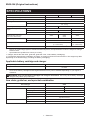
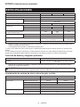
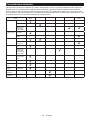
Instructions for periodic maintenance
To ensure long life, prevent damage and ensure the full functioning of the safety features, the following maintenance must
be performed regularly. Warranty claims can be recognized only if this work is performed regularly and properly. Failure to
perform the prescribed maintenance work can lead to accidents! The user of the chain saw must not perform maintenance
work which is not described in the instruction manual. All such work must be carried out by our authorized service center.
Check item / Operating time Before
operation
Everyday Every week Every 3
month
Annually Before
storage
Chain saw Inspection. -----
Cleaning. -----
Check at
authorized
service center.
----
Saw chain Inspection. -----
Sharpening if
necessary.
-----
Guide bar Inspection. ----
Remove from
the chain saw.
-----
Chain brake Check the
function.
-----
Have it inspected
regularly at
authorized
service center.
--- --
Chain
lubrication
Check the oil
feed rate.
-----
Switch trigger Inspection. -----
Inspection. -----
Oil tank cap Check
tightness.
-----
Chain catcher Inspection. - - ---
Screws and
nuts
Inspection. - - ---

18 ENGLISH
TROUBLESHOOTING
do not attempt to dismantle the tool. Instead, ask Makita Authorized Service Centers, always using Makita replace-
ment parts for repairs.
Malfunction status Cause Action
The chain saw does not start. Battery cartridge is not installed. Install a charged battery cartridge.
Battery problem (low voltage).
Recharge the battery cartridges. If recharging
it is un-operated for a certain period. Turn
on the main power switch again.
The saw chain does not run. Chain brake activated. Release chain brake.
The motor stops running after a little use. Battery's charge level is low.
Recharge the battery cartridges. If recharging
No oil on the chain. Oil tank is empty. Fill the oil tank.
Oil guide groove is dirty. Clean the groove.
Poor oil delivery.
The chain saw does not reach maximum
RPM.
Battery cartridge is installed improperly. Install the battery cartridges as described
in this manual.
Battery power is dropping.
Recharge the battery cartridge. If recharging
The drive system does not work correctly. Ask the authorized service center in your
region for repair.
The main power lamp is blinking in green. Switch trigger is pulled under an unoperat-
able condition.
Pull the switch trigger after the main power
switch is turned on and the chain brake is
released.
Chain does not stop even the chain brake
is activated:
Stop the machine immediately!
The brake band is worn down. Ask the authorized service center in your
region for repair.
Abnormal vibration:
Stop the machine immediately!
Loose guide bar or saw chain.
tension.
Tool malfunction. Ask the authorized service center in your
region for repair.
The Torque Boost mode is not available
after replacing the battery cartridge with a
fully charged one.
Depending on the usage conditions, the
Torque Boost mode is not available after
replacing the battery cartridge.
Use the tool in the normal mode until the
installed battery cartridge becomes empty, and
then replace the battery cartridge with a fully
charged one, or recharge the battery cartridge.
The saw chain cannot be installed. The combination of saw chain and
sprocket is not correct.
Use the correct combination of saw chain
and sprocket by referring to the section for
OPTIONAL ACCESSORIES
CAUTION: These accessories or attachments
are recommended for use with your Makita tool
The use of any other
accessories or attachments might present a risk of
for its stated purpose.
If you need any assistance for more details regard-
ing these accessories, ask your local Makita Service
Center.
• Saw chain
• Guide bar
• Guide bar cover
• Sprocket
• Spike bumper
• File
• Tool bag
• Makita genuine battery and charger
WARNING: If you purchase a guide bar of
purchase a suitable guide bar cover together. It
saw.
NOTE: Some items in the list may be included in the
tool package as standard accessories. They may

19 FRANÇAIS
FRANÇAIS (Instructions originales)
SPÉCIFICATIONS
Modèle : DUC204 DUC254 DUC254C
Longueur totale (sans guide-chaîne) 256 mm
Tension nominale 18 V CC
Poids net *1 2,0 kg
*2 2,8 - 3,3 kg
Longueur du guide-chaîne standard 200 mm 250 mm
Longueur de guide-chaîne
recommandée
avec 90PX 200 - 250 mm -
avec 91PX -250 mm -
avec 25AP -250 mm
Type de chaîne applicable
(reportez-vous au tableau ci-dessous.)
90PX 90PX
91PX
25AP
Pignon standard Nombre de dents 6 9
Pas
Vitesse de la chaîne 0 - 24 m/s
(0 - 1 440 m/min)
0 - 22,5 m/s
(0 - 1 350 m/min)
Capacité du réservoir d’huile pour chaîne 140 cm3
*1 : Poids, sans la chaîne, le guide-chaîne, le garde-chaîne, l’huile et la ou les batteries.
selon le ou les accessoires, notamment la ou les batteries.
Batterie et chargeur applicables
Batterie BL1815N / BL1820B / BL1830B / BL1840B / BL1850B / BL1860B
Chargeur DC18RC / DC18RD / DC18RE / DC18SD / DC18SE / DC18SF /
DC18SH
• Certains chargeurs et batteries répertoriés ci-dessus peuvent ne pas être disponibles selon la région où vous
résidez.
AVERTISSEMENT : N’utilisez que les batteries et les chargeurs répertoriés ci-dessus. L’utilisation
d’autres batteries et chargeurs peut provoquer des blessures et/ou un incendie.
Combinaison de chaîne, guide-chaîne et pignon
Type de chaîne 90PX
Nombre de maillons d’entraînement 33 40
Guide-chaîne Longueur du guide-chaîne 200 mm 250 mm
Longueur de coupe 171 mm 235 mm
Pas
Jauge 1,1 mm
Type
Pignon Nombre de dents 6
Pas

20 FRANÇAIS
Type de chaîne 91PX
Nombre de maillons d’entraînement 40
Guide-chaîne Longueur du guide-chaîne 250 mm
Longueur de coupe 235 mm
Pas
Jauge 1,3 mm
Type
Pignon Nombre de dents 6
Pas
Type de chaîne 25AP
Nombre de maillons d’entraînement 60
Guide-chaîne Longueur du guide-chaîne 250 mm
Longueur de coupe 250 mm
Pas
Jauge 1,3 mm
Type Guide-chaîne pour sculpture
Pignon Nombre de dents 9
Pas
REMARQUE :
Lorsque vous utilisez la chaîne 25AP, utilisez-la en association avec le pignon 9 (accessoire en option).
AVERTISSEMENT : Associez correctement guide-chaîne et chaîne. Le non-respect de cette consigne peut
entraîner des blessures.
Symboles
Vous trouverez ci-dessous les symboles susceptibles
Lire le mode d’emploi.
Portez des lunettes de sécurité.
Portez un dispositif de protection auditive.
un serre-tête antibruit.
Portez des protections adaptées pour les
Cette scie ne doit être utilisée que par des
opérateurs correctement formés.
Longueur de coupe maximale admise
lorsque vous utilisez la tronçonneuse.
Sens de déplacement de la chaîne
Ni-MH
Li-ion
Pour les pays de l’Union européenne
uniquement
En raison de la présence de composants
dangereux dans l’équipement, les déchets
d’équipements électriques et électro-
niques, les accumulateurs et les batteries
peuvent avoir un impact négatif sur l’envi-
ronnement et la santé humaine.
électroniques ou les batteries avec les
ordures ménagères !
relative aux déchets d’équipements élec-
triques et électroniques et aux déchets
les déchets d’équipements électriques,
les batteries et les accumulateurs doivent
être collectés séparément et déposés
dans un point de collecte distinct pour
déchets urbains, conformément aux régle-
mentations en matière de protection de
l’environnement.
Cela est indiqué par le symbole de la pou-
Niveau de puissance sonore garanti selon
la directive européenne sur le bruit dans
l’environnement.
Niveau de puissance sonore selon la
réglementation australienne NSW sur le
contrôle du bruit
Utilisations
L’outil est conçu pour la coupe des branches et l’éla-
arbres.
Sayfa yükleniyor...
Sayfa yükleniyor...
Sayfa yükleniyor...
Sayfa yükleniyor...
Sayfa yükleniyor...
Sayfa yükleniyor...
Sayfa yükleniyor...
Sayfa yükleniyor...
Sayfa yükleniyor...
Sayfa yükleniyor...
Sayfa yükleniyor...
Sayfa yükleniyor...
Sayfa yükleniyor...
Sayfa yükleniyor...
Sayfa yükleniyor...
Sayfa yükleniyor...
Sayfa yükleniyor...
Sayfa yükleniyor...
Sayfa yükleniyor...
Sayfa yükleniyor...
Sayfa yükleniyor...
Sayfa yükleniyor...
Sayfa yükleniyor...
Sayfa yükleniyor...
Sayfa yükleniyor...
Sayfa yükleniyor...
Sayfa yükleniyor...
Sayfa yükleniyor...
Sayfa yükleniyor...
Sayfa yükleniyor...
Sayfa yükleniyor...
Sayfa yükleniyor...
Sayfa yükleniyor...
Sayfa yükleniyor...
Sayfa yükleniyor...
Sayfa yükleniyor...
Sayfa yükleniyor...
Sayfa yükleniyor...
Sayfa yükleniyor...
Sayfa yükleniyor...
Sayfa yükleniyor...
Sayfa yükleniyor...
Sayfa yükleniyor...
Sayfa yükleniyor...
Sayfa yükleniyor...
Sayfa yükleniyor...
Sayfa yükleniyor...
Sayfa yükleniyor...
Sayfa yükleniyor...
Sayfa yükleniyor...
Sayfa yükleniyor...
Sayfa yükleniyor...
Sayfa yükleniyor...
Sayfa yükleniyor...
Sayfa yükleniyor...
Sayfa yükleniyor...
Sayfa yükleniyor...
Sayfa yükleniyor...
Sayfa yükleniyor...
Sayfa yükleniyor...
Sayfa yükleniyor...
Sayfa yükleniyor...
Sayfa yükleniyor...
Sayfa yükleniyor...
Sayfa yükleniyor...
Sayfa yükleniyor...
Sayfa yükleniyor...
Sayfa yükleniyor...
Sayfa yükleniyor...
Sayfa yükleniyor...
Sayfa yükleniyor...
Sayfa yükleniyor...
Sayfa yükleniyor...
Sayfa yükleniyor...
Sayfa yükleniyor...
Sayfa yükleniyor...
Sayfa yükleniyor...
Sayfa yükleniyor...
Sayfa yükleniyor...
Sayfa yükleniyor...
Sayfa yükleniyor...
Sayfa yükleniyor...
Sayfa yükleniyor...
Sayfa yükleniyor...
Sayfa yükleniyor...
Sayfa yükleniyor...
Sayfa yükleniyor...
Sayfa yükleniyor...
Sayfa yükleniyor...
Sayfa yükleniyor...
Sayfa yükleniyor...
Sayfa yükleniyor...
Sayfa yükleniyor...
Sayfa yükleniyor...
Sayfa yükleniyor...
Sayfa yükleniyor...
Sayfa yükleniyor...
Sayfa yükleniyor...
Sayfa yükleniyor...
Sayfa yükleniyor...
Sayfa yükleniyor...
Sayfa yükleniyor...
Sayfa yükleniyor...
Sayfa yükleniyor...
Sayfa yükleniyor...
Sayfa yükleniyor...
Sayfa yükleniyor...
Sayfa yükleniyor...
Sayfa yükleniyor...
Sayfa yükleniyor...
Sayfa yükleniyor...
Sayfa yükleniyor...
Sayfa yükleniyor...
Sayfa yükleniyor...
Sayfa yükleniyor...
Sayfa yükleniyor...
Sayfa yükleniyor...
Sayfa yükleniyor...
Sayfa yükleniyor...
Sayfa yükleniyor...
Sayfa yükleniyor...
Sayfa yükleniyor...
Sayfa yükleniyor...
Sayfa yükleniyor...
-
 1
1
-
 2
2
-
 3
3
-
 4
4
-
 5
5
-
 6
6
-
 7
7
-
 8
8
-
 9
9
-
 10
10
-
 11
11
-
 12
12
-
 13
13
-
 14
14
-
 15
15
-
 16
16
-
 17
17
-
 18
18
-
 19
19
-
 20
20
-
 21
21
-
 22
22
-
 23
23
-
 24
24
-
 25
25
-
 26
26
-
 27
27
-
 28
28
-
 29
29
-
 30
30
-
 31
31
-
 32
32
-
 33
33
-
 34
34
-
 35
35
-
 36
36
-
 37
37
-
 38
38
-
 39
39
-
 40
40
-
 41
41
-
 42
42
-
 43
43
-
 44
44
-
 45
45
-
 46
46
-
 47
47
-
 48
48
-
 49
49
-
 50
50
-
 51
51
-
 52
52
-
 53
53
-
 54
54
-
 55
55
-
 56
56
-
 57
57
-
 58
58
-
 59
59
-
 60
60
-
 61
61
-
 62
62
-
 63
63
-
 64
64
-
 65
65
-
 66
66
-
 67
67
-
 68
68
-
 69
69
-
 70
70
-
 71
71
-
 72
72
-
 73
73
-
 74
74
-
 75
75
-
 76
76
-
 77
77
-
 78
78
-
 79
79
-
 80
80
-
 81
81
-
 82
82
-
 83
83
-
 84
84
-
 85
85
-
 86
86
-
 87
87
-
 88
88
-
 89
89
-
 90
90
-
 91
91
-
 92
92
-
 93
93
-
 94
94
-
 95
95
-
 96
96
-
 97
97
-
 98
98
-
 99
99
-
 100
100
-
 101
101
-
 102
102
-
 103
103
-
 104
104
-
 105
105
-
 106
106
-
 107
107
-
 108
108
-
 109
109
-
 110
110
-
 111
111
-
 112
112
-
 113
113
-
 114
114
-
 115
115
-
 116
116
-
 117
117
-
 118
118
-
 119
119
-
 120
120
-
 121
121
-
 122
122
-
 123
123
-
 124
124
-
 125
125
-
 126
126
-
 127
127
-
 128
128
-
 129
129
-
 130
130
-
 131
131
-
 132
132
-
 133
133
-
 134
134
-
 135
135
-
 136
136
-
 137
137
-
 138
138
-
 139
139
-
 140
140
-
 141
141
-
 142
142
-
 143
143
-
 144
144


Makita DUC254 Kullanım kılavuzu
- Kategori
- Akülü motorlu testereler
- Tip
- Kullanım kılavuzu
- Bu kılavuz aynı zamanda aşağıdakiler için de uygundur:
diğer dillerde
- español: Makita DUC254 Manual de usuario
- français: Makita DUC254 Manuel utilisateur
- italiano: Makita DUC254 Manuale utente
- Deutsch: Makita DUC254 Benutzerhandbuch
- português: Makita DUC254 Manual do usuário
- dansk: Makita DUC254 Brugermanual
- Nederlands: Makita DUC254 Handleiding