INSTRUCTION AND
SERVICE MANUAL
ORIGINAL INSTRUCTION
AV™10 Installation Tool – 73430-02000
Hydro-Electric Power Tool
EN Hydro-Electric Power Tool
BG Хидро-електрически електроинструмент
HR Hidroelektrični alat
CZ Hydraulicko-elektrické nářadí
RO Unealtă hidro-electro-pneumatică
HU Hidroelektromos szerszám
SK Hydro-elektrické náradie
SL Hidravlično električno orodje
RU Электрогидравлический электроинструмент
AR
LV Hidropneimatiskais elektroinstruments
LT Hidraulinis-elektrinis įrankis
ET Hüdroelektriline tööriist
EL Υδραυλικό-Ηλεκτρικό Εργαλείο Ισχύος
TR Elektro Hidrolik Elektrikli Alet

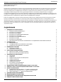
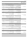
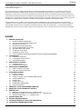
CONTENT
1. SAFETY DEFINITIONS 3
1.1 GENERAL SAFETY RULES 3
1.2 PROJECTILE HAZARDS 3
1.3 OPERATING HAZARDS 4
1.4 REPETITIVE MOTIONS HAZARDS 4
1.5 ACCESSORY HAZARDS 4
1.6 WORKPLACE HAZARDS 4
1.7 NOISE HAZARDS 4
1.8 VIBRATION HAZARDS 5
1.9 ADDITIONAL SAFETY INSTRUCTIONS FOR HYDRAULIC POWER TOOLS 5
2. SPECIFICATIONS 6
2.1 INTENT OF USE 6
2.2 PLACING TOOL SPECIFICATION 6
2.3 PLACING TOOL DIMENSIONS 7
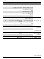
3. PUTTING INTO SERVICE 8
3.1 PRINCIPLE OF OPERATION 8
3.2 PREPARATION FOR USE 9
4. OPERATING INSTRUCTIONS 10
4.1 TO INSTALL AN AVBOLT® FASTENER 10
4.2 TO INSTALL AN AVDELOK® FASTENER 10
5. SERVICING THE TOOL 11
5.1 DAILY 11
5.2 WEEKLY 11
5.3 ANNUALLY OR EVERY 250K OPERATIONS 11
5.4 SERVICE KIT 11
5.5 SERVICING TOOLS' 11
5.6 HYDRAULIC OIL 12
5.7 DISMANTLING INSTRUCTIONS 12
5.8 PROTECTING THE ENVIRONMENT 14
6. GENERAL ASSEMBLY OF INSTALLATION TOOL 73430-02000 15
7. PARTS LIST FOR INSTALLATION TOOL 73430-02000 17
8. SAFETY DATA 18
8.1 ENERPAC® HF HYDRAULIC OIL - SAFETY DATA 18
8.2 MOLYLITHIUM GREASE EP 3753 - SAFETY DATA 18
8.3 MOLYKOTE® 111 GREASE - SAFETY DATA 19
9. FAULT DIAGNOSIS 20
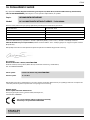
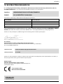
10. EC DECLARATION OF CONFORMITY 22
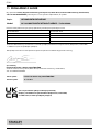
11. UK DECLARATION OF CONFORMITY 23
12. PROTECT YOUR INVESTMENT! 24
©2019STANLEY Black & Decker
All rights reserved.
The information provided may not be reproduced and/or made public in any way and through any means (electronically
or mechanically) without prior explicit and written permission from STANLEY Engineered Fastening. The information
provided is based on the data known at the moment of the introduction of this product. STANLEY Engineered Fastening
pursues apolicy of continuous product improvement and therefore the products may be subject to change. The information
provided is applicable to the product as delivered by STANLEY Engineered Fastening. Therefore, STANLEY Engineered
Fastening cannot be held liable for any damage resulting from deviations from the original specications of the product.
The information available has been composed with the utmost care. However, STANLEY Engineered Fastening will not
accept any liability with respect to any faults in the information nor for the consequences thereof. STANLEY Engineered
Fastening will not accept any liability for damage resulting from activities carried out by third parties. The working names,
trade names, registered trademarks, etc. used by STANLEY Engineered Fastening should not be considered as being free,
pursuant to the legislation with respect to the protection of trade marks.
2
ENGLISH ORIGINAL INSTRUCTION

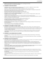
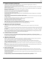
This instruction manual must be read by any person installing or operating this tool with particular attention to
the following safety rules.
Always wear impact-resistant eye protection during operation of the tool. The grade of protection required
should be assessed for each use.
Use of the tool can expose the operator’shands to hazards, including crushing, impacts, cuts and abrasions and
heat. Wear suitable gloves to protect hands.
Use hearing protection in accordance with employer’sinstructions and as required by occupational health and
safety regulations.
1. SAFETY DEFINITIONS
The definitions below describe the level of severity for each signal word. Please read the manual and pay attention to these
symbols.
DANGER: Indicates an imminently hazardous situation which, if not avoided, will result in death or serious injury.
WARNING: Indicates apotentially hazardous situation which, if not avoided, could result in death or serious injury.
CAUTION: Indicates apotentially hazardous situation which, if not avoided, may result in minor or moderate injury.
CAUTION: Used without the safety alert symbol indicates apotentially hazardous situation which, if not avoided, may
result in property damage.
Improper operation or maintenance of this product could result in serious injury and property damage. Read and
understand all warnings and operating instructions before using this equipment.
When using power tools, basic safety precautions must always be followed to reduce the risk of personal injury.
SAVE ALL WARNINGS AND INSTRUCTIONS FOR FUTURE REFERENCE
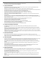
1.1 GENERAL SAFETY RULES
• For multiple hazards, read and understand the safety instructions before installing, operating, repairing, maintaining,
changing accessories on, or working near the tool. Failure to do so can result in serious bodily injury.
• Only qualied and trained operators must install, adjust or use the tool.
• DO NOT use outside the design intent of placing STANLEY Engineered Fastening Blind Rivets.
• Use only parts, fasteners, and accessories recommended by the manufacturer.
• DO NOT modify the tool. Modications can reduce the eectiveness of safety measures and increase the risks to the
operator. Any modication to the tool undertaken by the customer will be the customer’sentire responsibility and void
any applicable warranties.
• Do not discard the safety instructions; give them to the operator.
• Do not use the tool if it has been damaged.
• Prior to use, check for misalignment or binding of moving parts, breakage of parts, and any other condition that aects
the tool’soperation. If damaged, have the tool serviced before using. Remove any adjusting key or wrench before use.
• Tools shall be inspected periodically to verify that the ratings and markings required by this part of ISO 11148are legibly
marked on the tool. The employer/user shall contact the manufacturer to obtain replacement marking labels when
necessary.
• The tool must be maintained in asafe working condition at all times and examined at regular intervals for damage
and function by trained personnel. Any dismantling procedure will be undertaken only by trained personnel. Do not
dismantle this tool without prior reference to the maintenance instructions.
1.2 PROJECTILE HAZARDS
• Disconnect the tool from the hydraulic pump unit before performing any maintenance, attempting to adjust, fit or
remove anose assembly or accessories.
• Be aware that failure of the workpiece or accessories, or even of the inserted tool itself can generate high-velocity
projectiles.
• Always wear impact-resistant eye protection during operation of the tool. The grade of protection required should be
assessed for each use.
• The risks to others should also be assessed at this time.
• Ensure that the workpiece is securely fixed.
• Check that the means of protection from ejection of fastener and/or mandrel is in place and is operative.
• Warn against the possible forcible ejection of mandrels from the front of the tool.
• DO NOT operate atool that is directed towards any person(s).
3
ENGLISH

1.3 OPERATING HAZARDS
• Use of the tool can expose the operator’shands to hazards, including crushing, impacts, cuts and abrasions and heat.
Wear suitable gloves to protect hands.
• Operators and maintenance personnel shall be physically able to handle the bulk, weight and power of the tool.
• Hold the tool correctly; be ready to counteract normal or sudden movements and have both hands available.
• Keep tool handles dry, clean, and free from oil and grease.
• Maintain abalanced body position and secure footing when operating the tool.
• Release the start-and-stop device in the case of an interruption of the hydraulic supply.
• Use only lubricants recommended by the manufacturer.
• Contact with hydraulic fluid should be avoided. To minimise the possibility of rashes, care should be taken to wash
thoroughly if contact occurs.
• Material Safety Data Sheets for all hydraulic oils and lubricants is available on request from your tool supplier.
• Avoid unsuitable postures as it is likely for these positions not to allow counteracting of normal or unexpected
movement of the tool.
• If the tool is fixed to asuspension device, make sure that the fixation is secure.
• Beware of the risk of crushing or pinching if nose equipment is not fitted.
• DO NOT operate tool with the nose casing removed.
• Adequate clearance is required for the tool operator’shands before proceeding.
• When carrying the tool from place to place keep hands away from the trigger to avoid inadvertent activation.
• DO NOT abuse the tool by dropping or using it as ahammer.
• Care should be taken to ensure that spent mandrels do not create ahazard.
1.4 REPETITIVE MOTIONS HAZARDS
• When using the tool, the operator can experience discomfort in the hands, arms, shoulders, neck or other parts of the
body.
• While using the tool, the operator should adopt acomfortable posture whilst maintaining asecure footing and
avoiding awkward or off-balance postures. The operator should change posture during extended tasks; this can help
avoid discomfort and fatigue.
• If the operator experiences symptoms such as persistent or recurring discomfort, pain, throbbing, aching, tingling,
numbness, burning sensations or stiffness, these warning signs should not be ignored. The operator should tell the
employer and consult aqualified health professional.
1.5 ACCESSORY HAZARDS
• Disconnect the tool from the hydraulic and electrical supply before fitting or removing the nose assembly or accessory.
• Use only sizes and types of accessories and consumables that are recommended by the manufacturer of the tool; do
not use other types or sizes of accessories or consumables.
1.6 WORKPLACE HAZARDS
• Slips, trips and falls are major causes of workplace injury. Be aware of slippery surfaces caused by use of the tool and
also of trip hazards caused by the air line or hydraulic hose.
• Proceed with care in unfamiliar surroundings. There can be hidden hazards, such as electricity or other utility lines.
• The tool is not intended for use in potentially explosive atmospheres and is not insulated against contact with electric
power.
• Ensure that there are no electrical cables, gas pipes, etc., which can cause ahazard if damaged by use of the tool.
• Dress properly. Do not wear loose clothing or jewellery. Keep your hair, clothing and gloves away from moving parts.
Loose clothes, jewellery or long hair can be caught in moving parts.
• Care should be taken to ensure that spent mandrels do not create ahazard.
1.7 NOISE HAZARDS
• Exposure to high noise levels can cause permanent, disabling hearing loss and other problems, such as tinnitus
(ringing, buzzing, whistling or humming in the ears). Therefore, risk assessment and the implementation of appropriate
controls for these hazards are essential.
• Appropriate controls to reduce the risk may include actions such as damping materials to prevent workpieces from
“ringing”.
• Use hearing protection in accordance with employer’sinstructions and as required by occupational health and safety
regulations.
• Operate and maintain the tool as recommended in the instruction manual, to prevent an unnecessary increase in the
noise level.
4
ENGLISH

1.8 VIBRATION HAZARDS
• Exposure to vibration can cause disabling damage to the nerves and blood supply of the hands and arms.
• Wear warm clothing when working in cold conditions and keep your hands warm and dry.
• If you experience numbness, tingling, pain or whitening of the skin in your fingers or hands, stop using the tool, tell
your employer and consult aphysician.
• Where possible Support the weight of the tool in astand, tensioner or balancer, because alighter grip can then be used
to support the tool.
1.9 ADDITIONAL SAFETY INSTRUCTIONS FOR HYDRAULIC POWER TOOLS
• The operating hydraulic supply must not exceed 550bar (8000PSI).
• Oil under pressure can cause severe injury.
• Do not fit flexible hydraulic hoses rated at less than 700 bar (10,000 PSI) working pressure at a flow rate of 2.73 l/min
(200 in3/min).
• Never leave operating tool unattended. Disconnect hydraulic hose and electrical cable from the pump unit when tool is
not in use, before changing accessories or when making repairs.
• Whipping hoses can cause severe injury. Always check for damaged or loose hoses and fittings.
• Prior to use, inspect hydraulic hoses for damage, all hydraulic connections must be clean, fully engaged and tight
before operation. Do not drop heavy objects on hoses. Asharp impact may cause internal damage and lead to
premature hose failure.
• Whenever universal twist couplings (claw couplings) are used, lock pins shall be installed and whipcheck safety cables
shall be used to safeguard against possible hose-to-tool or hose-to-hose connection failure.
• DO NOT lift the placing tool by the hose or electrical cable. Always use the placing tool handle.
• DO NOT pull or move the hydraulic pump unit using the hoses. Always use the pump unit handle or roll cage.
• Keep dirt and foreign matter out of the hydraulic system of the tool as this will cause the tool to malfunction.
• Use only clean oil and filling equipment.
• Only recommended hydraulic fluids may be used.
• Power units require a free flow of air for cooling purposes and should therefore be positioned in a well ventilated area
free from hazardous fumes.
• Maximum temperature of the hydraulic fluid at the inlet is 110°C (230°F).
STANLEY Engineered Fastening policy is one of continuous product development and improvement and we reserve
the right to change the specification of any product without prior notice.
5
ENGLISH

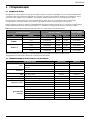
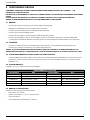
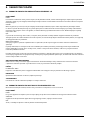
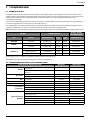
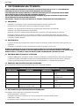
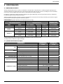
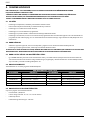
2. SPECIFICATIONS
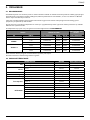
2.1 INTENT OF USE
The AV™10 Installation Tool is principally a piston and cylinder assembly. When coupled hydraulically and electrically to
acompatible hydraulic power source and the relevant nose assembly is attached, it is then used to install 3/8” Avdelok®,
5/16” to 3/8” Avbolt® and Ø18mm Avseal® II in Industrial Environments.
The placing tool and hydraulic pump unit may only be used in accordance with the operating instructions for placing
Stanley Engineered Fastening structural rivets.
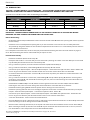
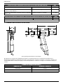
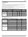
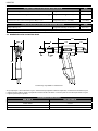
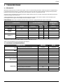
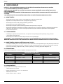
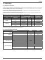
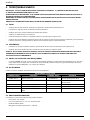
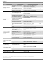
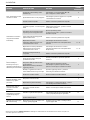
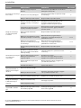
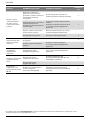
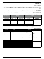
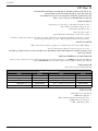
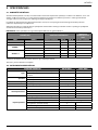
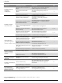
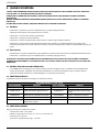
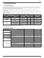
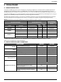
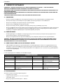
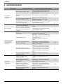
Refer to the table below for the list of applicable fasteners and associated nose equipment. Refer to the datasheets listed in
the table for the relevant nose assembly instructions.
DO NOT use under wet conditions or in the presence of flammable liquids or gases.
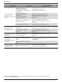
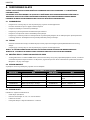
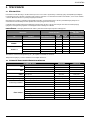
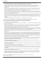
FASTENER NOSE ASSEMBLY
NOSE ASSEMBLY
DATASHEET
TYPE SIZE PART NUMBER DIM. ‘A’ DIM. ‘B’ PART NUMBER
AVDELOK® 3/8” 73430-03100 87 mm 28 mm 07900-00919
AVBOLT® 5/16” 73430-03300 92 mm 27 mm 07900-00905
3/8” 73430-03200 92 mm 29 mm 07900-00905
AVSEAL® II
16 mm 73430-05000 95 mm 27 mm 07900-00840
16 mm flanged 73430-05000 95 mm 27 mm 07900-00840
18 mm 73430-05200 95 mm 27 mm 07900-00840
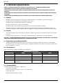
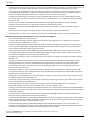
Refer to the illustration on page 7 for the identification of the nose assembly dimensions ‘A’ and ‘B’.
The safety instructions must be followed at all times.
2.2 PLACING TOOL SPECIFICATION
SPECIFICATION METRIC IMPERIAL
Force: Pull at stated pull pressure 55.0 kN 12364.0 lbf
Push O at stated return pressure 26.0 kN 5485.0 lbf
Pressure: Pull 510 bar 7397 PSI
Return 200 bar 2901 PSI
Stroke: Piston Stroke 25.0 mm 0.98 in
Weight: Without nose equipment 3.5 kg 7.7 lb
Hydraulic Oil: Enerpac® Hydraulic Oil – HF-95X
Product Range:
Avbolt® 10.0 mm 3/8 in
Avseal® II 18.0 mm
Avdelok® 10.0 mm 3/8 in
Additional Features:
Stem Ejection – Front or Rear Rear
Seal Arrangement Twin Lip and Wiper Seals
Hydraulic Bearing Rings Yes – Front and Rear
Protective Handle / Hose Gator Yes
Protective Hose Guard Yes
Hose
/
Cable Retention Clamps
Yes
6
ENGLISH

Noise values determined according to noise test code ISO 15744and ISO 3744. AV10
A-weighted sound power level dB(A), LWA Uncertainty noise: kWA = 3.0dB(A) 93.3 dB(A)
A-weighted emission sound pressure level at the work station
dB(A), LpA
Uncertainty noise: kpA = 3.0dB(A) 82.3 dB(A)
C-weighted peak emission sound pressure level dB(C), LpC, peak Uncertainty noise: kpC = 3.0dB(C) 127.7 dB(C)
Vibration values determined according to vibration test code ISO 20643and ISO 5349. AV10
Vibration emission level, ahd: Uncertainty vibration: k= 0.33m/s20.661 m/s2
Declared vibration emission values in accordance with EN 12096
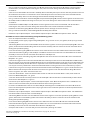
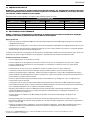
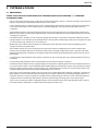
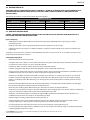
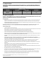
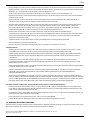
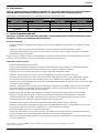
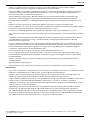
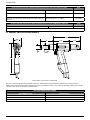
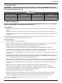
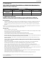
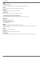
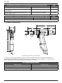
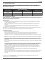
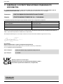
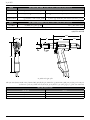
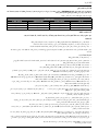
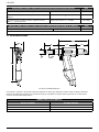
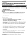
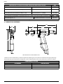
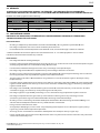
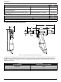
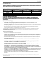
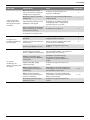
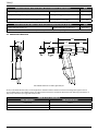
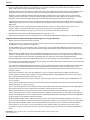
2.3 PLACING TOOL DIMENSIONS
117
236
56
33
79
197
A
B
All dimensions are shown in millimetres.
The tool is fitted with two Hydraulic Hoses and an electrical Control Cable, 0.6m in length. Additional hydraulic hose
and cable extension lengths are available to order separately as required. Refer to the table below for the available hose
assembly lengths and associated part numbers.
HYDRAULIC HOSE ASSEMBLY
PART NUMBER HOSE LENGTH
07008–00448 5 Metre
07008–00449 10 Metre
07008–00450 15 Metre
7
ENGLISH

3. PUTTING INTO SERVICE
3.1 PRINCIPLE OF OPERATION
IMPORTANT - READ BOTH THE SAFETY RULES ON PAGES
3 – 5
AND THE PUMP UNIT INSTRUCTION MANUAL
CAREFULLY BEFORE PUTTING INTO SERVICE.
•
When both hoses and control cable are connected to the Avdel®
/
Enerpac® hydraulic pump unit, the pull and return
cycles of
the tool are controlled by depressing and releasing the trigger located in the handle.
• When the switch is depressed the solenoid valve, located in the hydraulic pump unit, is energised and directs the
pressurised oil flow to the pull side of the piston in the placing tool. This also allows the oil in the return side of the
placing tool to return to the reservoir.
•
During the pull cycles the piston/collet assembly moves towards the rear of the tool allowing the O-ring type cushion to push
the follower and jaws forward. If a fastener pin has been inserted in the nose assembly, the jaw set will clamp onto
the pintail
and assembly will commence.
•
For Avbolt® and Avdelok® the cycle of installation will first clamp the joint to be fastened and then as the anvil continues to
move forward the collar will be swaged into the locking grooves of the pin. At the end of the swaging cycle the anvil
will
come up against the joint and as movement continues the pintail will be broken off.
•
The trigger switch should be released immediately after pin break occurs. Releasing the trigger switch will cause the
solenoid
to de-energise and reverse the flow of pressurised oil.
•
If the trigger is not released, the placing tool piston will continue to move towards the rear of the tool until it reaches the end
of its stroke. The pressure in the pull side will then increase until a preset ‘High Pressure’ value is achieved at the pump.
At this point the solenoid valve will automatically de-energise and reverse the flow of pressurised oil to the return
side of the
placing tool.
•
In either case, pressurised oil will now flow into the return side of the placing tool, with the oil in the pull side returning
to the
reservoir.
• The forward movement of the piston/collet assembly will eject the installed fastener from the anvil.
•
At the point of releasing the trigger or when the ‘High Pressure’ value is achieved, the solenoid valve will de-energise and
activate a preset ‘Return Timer’. This controls the time that the pump motor will continue run before switching to the idle
mode. The timer can be manually set between 5 and 20 seconds to ensure that the placing tool piston always fully
returns to the forward position (refer to pump manual 07900-01030, pages 11 and 14).
•
When the piston returns to the fully forward position, the pressure will increase to preset low pressure value - c200bar.
The pump motor will continue to run until the Return Timer has expired. After this time period the motor will stop
automatically and valve will switch to the idle position. The solenoid valve will then automatically cycle to release
pressurised
oil to the reservoir from both the pull and return side of the placing tool.
•
This keeps the installation tool in the forward position. No pressure will be present in the hydraulic system at this point.
The
hydraulic pump unit will automatically start up on depression of the tool trigger switch.
8
ENGLISH

3.2 PREPARATION FOR USE
CAUTION - CORRECT PULL AND RETURN PRESSURES ARE IMPORTANT FOR PROPER FUNCTION OF THE ISTALLATION
TOOL. PERSONAL INJURY OR DAMAGE TO EQUIPMENT MAY OCCUR WITHOUT CORRECT PRESSURES. THE PULL AND
RETURN PRESSURES SUPPLIED BY THE HYDRAULIC PUMP UNIT MUST NOT EXCEED THOSE PRESSURES LISTED IN THE
PLACING TOOL SPECIFICATION.
IMPORTANT – BEFORE PUTTING THE PLACING TOOL AND HYDRAULIC HOSE SET INTO SERVICE:
ENSURE THAT THE PUMP PRESSURE RELIEF VALVES HAVE BEEN SET IN ACCORDANCE WITH THE PUMP INSTRUCTIONS
AND THE MAXIMUM PRESSURES SPECIFIED FOR THE PLACING TOOL AND HOSES.
ENSURE THAT THE HOSE KIT IS PRIMED WITH HYDRAULIC FLUID IN ACCORDANCE WITH THE PROCEDURE IN THE
PUMP INSTRUCTION MANUAL 07900-01030.
• Ensure the mains power supply to the hydraulic pump unit is switched off.
• Connect the placing tool hydraulic hose quick couplers directly to the pump unit before connecting the electrical
control cable. Hoses and control cable must be connected in this order and disconnected in reverse order.
• Switch on the mains supply to the hydraulic pump unit. Wait 5 seconds for the pump unit to complete the boot
sequence, before pressing the trigger switch. When all set the LCD screen on the pump unit will display ‘AVDEL’.
• During the boot sequence the pump control system identifies any trigger operation as a potential malfunction and
prevents the motor from starting. The LCD screen will display ‘BUTTON FAULT’ in this instance. Reset by switching off the
power supply for 10 seconds.
• Ensure that the placing tool is positioned below the pump reservoir tanks. Depress and release the placing tool trigger
switch a few times to almost the full stroke of the tool to circulate hydraulic fluid and expel any air from the tool.
• Observe action of tool. Check for fluid leaks and ensure that in the idler mode the piston is in the fully forward position.
The placing tool will now be primed.
• Switch off the mains power supply to the hydraulic pump unit and then disconnect the placing tool from the pump
unit in reverse order to that described above.
• Now connect the placing tool to the primed hydraulic hose kit and electrical control cable. Then connect hydraulic hose
kit quick couplers and the electrical control cable to the pump unit.
• Attach the nose assembly to the tool as per the instructions in the relevant nose assembly datasheet.
• Switch on the mains supply to the hydraulic pump unit as described above.
• Depress and release the placing tool trigger switch a few times to almost the full stroke of the tool to circulate hydraulic
fluid.
• The placing tool is now ready for use.
9
ENGLISH

4. OPERATING INSTRUCTIONS
4.1 TO INSTALL AN AVBOLT® FASTENER
• Check work and remove excessive gap. (Gap is the space between components of the Joint. Gap is excessive if not
enough pintail sticks through the collar for the nose assembly jaws to grab onto).
• Put Avbolt® fastener into hole.
• Push nose assembly onto the pin until the nose assembly anvil stops against the collar. Tool and nose assembly must be
held at right angles (90°) to the work.
• Depress tool trigger switch to start installation cycle.
• When the forward motion of the nose assembly anvil stops and the pintail breaks o, release the trigger. The tool will
go into its return stroke and push o the installed fastener. At the end of the return stroke the jaws will partially release
the expended pintail which can then be pushed through the jaws with the next installation and then ejected through
the rear of the tool.
• Once the installed fastener has been ejected, the tool and nose assembly is ready for the next installation.
4.2 TO INSTALL AN AVDELOK® FASTENER
• Check work and remove excessive gap. (Gap is the space between components of the Joint. Gap is excessive if not
enough pintail sticks through the collar for the nose assembly jaws to grab onto).
• Put Avdelok® fastener into hole.
• Slide Avdelok® collar over the pin. (The beveled end of the collar must be towards the nose assembly and tool.)
• Push nose assembly onto the pin until the nose assembly anvil stops against the collar. Tool and nose assembly must be
held at right angles (90°) to the work.
• Depress tool trigger switch to start installation cycle.
• When the forward motion of the nose assembly anvil stops and the pintail breaks off, release the trigger. The tool will
go into its return stroke and push off the installed fastener. At the end of the return stroke the jaws will partially release
the expended pintail which can then be pushed through the jaws with the next installation and then ejected through
the rear of the tool.
• Once the installed fastener been ejected, the tool and nose assembly is ready for the next installation.
CAUTION - DO NOT ATTEMPT TO BREAK OFF A PINTAIL WITHOUT THE INSTALLATION OF A COLLAR AS THIS WILL
CAUSE THE UNSECURED PORTION OF THE AVDELOK® OR AVBOLT® PINTAIL TO EJECT FROM THE NOSE AT A HIGH
SPEED AND FORCE.
10
ENGLISH

5. SERVICING THE TOOL
IMPORTANT - READ BOTH THE SAFETY RULES ON PAGES 3 – 5 AND THE PUMP UNIT INSTRUCTION MANUAL
CAREFULLY BEFORE PUTTING INTO SERVICE.
THE EMPLOYER IS RESPONSIBLE FOR
ENSURING THAT TOOL MAINTENANCE INSTRUCTIONS ARE GIVEN TO THE
APPROPRIATE PERSONNEL.
THE OPERATOR SHOULD NOT BE INVOLVED IN MAINTENANCE OR REPAIR OF THE TOOL UNLESS PROPERLY
TRAINED.
THE TOOL SHALL BE EXAMINED REGULARLY FOR DAMAGE AND MALFUNCTION.
5.1 DAILY
• Check placing tool, hoses and quick couplers for oil leaks.
• Worn or damaged hoses and couplings should be replaced.
• Check that the stroke of tool meets the specification.
• Check that the stem deflector is fitted.
• Check that the pump pull / advance pressure relief valve is functioning correctly.
• Check for worn anvil indicated by score marks on the installed collar. This can also be confirmed by referring to the
installed data in the fastener catalogue. Excessive wear can cause the anvil to rupture.
5.2 WEEKLY
• Dismantle and clean the nose assembly especially the jaws as described in the relevant nose assembly datasheet.
• Check for oil leaks in placing tool, hoses and quick couplers.
CAUTION NEVER USE SOLVENTS OR OTHER HARSH CHEMICALS FOR CLEANING THE NONMETALLIC PARTS OF
THE TOOL. THESE CHEMICALS MAY WEAKEN THE MATERIALS USED IN THESE PARTS
5.3 ANNUALLY OR EVERY 250K OPERATIONS
• Every 250,000 cycles the tool should be completely dismantled and new components should be used where worn,
damaged or as recommended. All O-rings, back-up rings and seals should be renewed and lubricated with MolyKote®
111 grease before assembling.
5.4 SERVICE KIT
For a complete service the following Service Kit is available:
SERVICE KIT: 73430-99990
PART NUMBER DESCRIPTION PART NUMBER DESCRIPTION
07005-10118 Quick Coupler - Male 07900-00956 AV10 Piston Guide Sleeve
07005-10120 Quick Coupler - Female 07900-00957 AV10 End Cap Assembly Tool
07900-00951 AV10 Piston Bullet - Front 07992-00020 Grease – MolyLithium EP3753
07900-00952 AV10 Piston Bullet - Rear 07900-00755 Grease – Molykote 111
07900-00955 AV10 Front Gland Guide Rod 07900-00756 Loctite® 243 Threadlocker
5.5 SERVICING TOOLS'
The following standard tools are also required:
• Allen Key: 2.0 / 3.0 mm
• Open End Flat Spanner: 12 / 14 / 18 / 24 / 45 mm A/F
• PTFE Tape: 10 mm
• Engineers Vice with Jaw Guards – 150 mm
11
ENGLISH

5.6 HYDRAULIC OIL
CAUTION USE ONLY ENERPAC® HF HYDRAULIC OIL THE USE OF ANY OTHER OIL MAY CAUSE THE PLACING TOOL
AND PUMP TO MALFUNCTION AND WILL RENDER THE PLACING TOOL WARRANTY NULL AND VOID.
Hydraulic oil is available to order under the following part numbers.
HYDRAULIC OIL
PART NUMBER 07992-00081 07992-00082 07992-00083
Enerpac® Part Number HF-95X
HF-95Y HF-95T
Volume 1 Litre 5 Litres 20 Litres
Viscosity 32 mm2/s 32 mm2/s 32 mm2/s
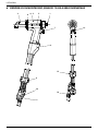
5.7 DISMANTLING INSTRUCTIONS
IMPORTANT – ENSURE THE MAINS POWER SUPPLY TO THE HYDRAULIC PUMP UNIT IS SWITCHED OFF BEFORE
REMOVING THE NOSE ASSEMBLY OR DISMANTLING THE PLACING TOOL.
Before Dismantling:
• Uncouple the Quick Couplers 10 and 11 and the electrical Control Cable 14 between the placing tool and the Hydraulic
Hose Assembly.
• Remove the nose assembly from the placing tool as per the instructions in the relevant nose assembly datasheet.
• The potentially dangerous substances that could have deposited on the machine as a result of work processes must be
removed before maintenance.
For a complete service of the tool, we advise that you proceed with dismantling the tool in the order shown on pages 12
to 14. After dismantling the tool we recommend that you replace all seals.
Head Piston Assembly:
• Remove the Deflector 3, from the End Cap 17.
• Clamp the tool handle in a vice with soft jaws so that the tool is pointing nose down. Insert the dowel pins on the *End
Cap Assembly Tool into the three holes in the End Cap 17.
• Using a 24 mm A/F spanner, unscrew and remove the End Cap 17, from the Body 2.
• Using a small flat screwdriver, remove O-Ring 33 from the End Cap 17 and discard.
• Connect the spare *Quick Coupler – Male to the Quick Coupler – Female 11 on the Hydraulic Hose - Return 18. This will
release any pressure from the return side of the Piston 1 and ease the removal of the Rear Seal Gland 16.
• Insert three M4 screws into the Rear Seal Gland 16, and use them to pull the part off the rear shaft of the Piston 1 and
out of the Body 2.
• Using a small flat screwdriver or similar tool, remove O-Ring 30 and Spiral Back-up Ring 36, from the external groove
on the Rear Seal Gland 16, and discard. When removing the seals, take care not to damage the surface of the Rear Seal
Gland with the screwdriver.
• Remove Rod Seal 28 and Wiper Seal 31, from the internal grooves on the Rear Seal Gland 16, and discard. When
removing the seals, take care not to damage the surface of the Rear Seal Gland with the screwdriver.
• Remove Rear Bearing Ring 29 and check the part for wear or damage. Discard if necessary.
• Remove the placing tool from the vice and empty the hydraulic oil from the rear of the tool. Remove the spare *Quick
Coupler – Male from the Quick Coupler – Female 11 on Hydraulic Hose - Return 18.
• Connect the spare *Quick Coupler - Female to the Quick Coupler – Male 10 on the Hydraulic Hose - Pull 19. This will
release any pressure from the pull side of the Piston 1 and ease the removal of the Piston.
• Screw the *Piston Bullet - Front on to the front of the Piston 1.
• Place the Body 2 nose up on a bench. Then using a soft mallet, tap the Piston 1 towards the rear of the Body and out the
back end, taking care not to damage the bore within the Body.
• Note that when removing the Piston 1, oil on the pull side of the Piston will leak from the front and rear of the Body 2.
• When removing the Piston 1, the Front Seal Gland 15 may be retained on the Piston shaft. If this is the case, unscrew
the *Piston Bullet - Front and pull the Front Seal Gland off of the Piston.
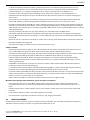
All numbers in bold refer to the General Assembly and Parts List on pages 15, 16 and 17.
*Service Kit on page 11
12
ENGLISH

• Using a small flat screwdriver remove Piston Seal 26 and the two Anti-Extrusion Rings 27, from the external groove
on the Piston 1, and discard. When removing the seals, take care not to damage the surface of the Piston with the
screwdriver.
• If the Front Seal Gland 15 is still retained in the Body 2. Place the Body nose up on a bench and then push the Front Seal
Gland from the front until it is free from the recess within Body. The Front Seal Gland can then be removed from the
back end of the Body. Take care not to damage the bore within the Body when doing so.
• Using a small flat screwdriver remove O-Ring 23 and Spiral Back-up Ring 34, from the external groove on the Front Seal
Gland 15, and discard. When removing the seals, take care not to damage the surface of the Front Seal Gland with the
screwdriver.
• Remove Rod Seal 25 and Wiper Seal 22, from the internal grooves on the Front Seal Gland 15, and discard. When
removing the seals, take care not to damage the surface of the Front Seal Gland with the screwdriver.
• Remove the Front Bearing Ring 24 and check the part for wear or damage. Discard if necessary.
• Using a small flat screwdriver, remove O-Ring 21 from the Body 2 and discard.
• Remove the spare *Quick Coupler - Female from the Quick Coupler - Male 10 on the Hydraulic Hose - Pull 19.
Assemble in reverse order to dismantling noting the following points:
• Clean all components before assembling.
• To aid assembly of seals apply a light coating of Molykote® 111 grease to all seals, seal grooves, back-up rings and the
assembly tools.
• Slide O-Ring 23 over the Front Seal Gland 15 and into the external groove. Insert the Spiral Back-up Ring 34 in the same
groove, in front of the installed O-Ring. Refer to the General Assembly and Parts List for the correct orientation of the
O-Ring and Spiral Back-up Ring.
• Press the Front Bearing Ring 24 into the internal recess within the Front Seal Gland 15 and then install Rod Seal 25
behind the Front Bearing Ring. Install the Wiper Seal 22 in the front recess of the Front Seal Gland. Refer to the General
Assembly to ensure the correct orientation of the Rod Seal and Wiper Seal.
• Lubricate the surface and leading edge of the Body 2 bore into which the Front Seal Gland 15 is to be installed with
Molykote® 111 grease.
• Lubricate the spigot on the *Front Gland Guide Rod tool and then place the Front Seal Gland 15, Rod Seal 25 end first,
fully over spigot. Insert *Front Gland Guide Rod into the rear of the Body 2 and then push the Front Seal Gland fully into
the bore within the Body. Reasonable force is required to insert Front Seal Gland into the Body, so the use of a press or
vice may be necessary. Remove the *Front Gland Guide Rod while ensuring that the Front Seal Gland stays in place.
• Lubricate the seal groove and major external diameter of the Piston 1 with Molykote® 111 grease. Slide the Piston Seal
26 over the front of the major Piston diameter and into the seal groove. Install two Anti-Extrusion Rings 27 into the
Piston seal groove, one either side of the Piston Seal.
• Screw the *Piston Bullet - Front onto the front of the Piston 1. Lubricate the *Piston Bullet - Front, Piston shaft and
Piston Seal 26 with Molykote® 111 grease.
• Screw the *Piston Guide Sleeve fully into the rear of the Body 2. Lubricate the bores in both the Body and the *Piston
Guide Sleeve with Molykote® 111 grease.
• Connect the spare *Quick Coupler - Female to the Quick Coupler - Male 10 on the Hydraulic Hose - Pull 19. This will
allow air to be released from the pull side of the Piston 1 when inserting the Piston.
• Insert the assembled Piston 1 into the rear of the Body 2 and through the assembled Front Seal Gland 15. Push the
Piston into the fully forward position until it stops against the Front Seal Gland. Hydraulic oil will be expelled from the
Hydraulic Hose - Pull 19.
• Remove the spare *Quick Coupler - Female from the Quick Coupler - Male 10 on the Hydraulic Hose - Pull 19. Remove
the *Piston Guide Sleeve from the rear of the Body 2.
• Slide O-Ring 30 over the Rear Seal Gland 16 and into the external groove. Insert the Spiral Back-up Ring 36 in the same
groove, behind the installed O-Ring. Refer to the General Assembly and Parts List for the correct orientation of the
O-Ring and Spiral Back-up Ring.
• Press the Rear Bearing Ring 29 into the internal recess within the Rear Seal Gland 16 and then install Rod Seal 28
behind the Rear Bearing Ring. Install the Wiper Seal 31 in the rear recess of the Rear Seal Gland. Refer to the General
Assembly to ensure the correct orientation of the Rod Seal and Wiper Seal.
• Clamp the tool handle in a vice with soft jaws so that the tool is pointing nose down.
All numbers in bold refer to the General Assembly and Parts List on pages 15, 16 and 17.
*Service Kit on page 11
13
ENGLISH

• Lubricate the surface and leading edge of the Body 2 bore into which the Rear Seal Gland 16 is to be installed with
Molykote® 111 grease. Lubricate the rear Piston 1 shaft with Molykote® 111 grease.
• Insert the *Piston Bullet - Rear into the rear Piston 1 shaft and Lubricate with Molykote® 111 grease.
• Fill the rear of the Body 2 with Enerpac® HF hydraulic oil. Oil level should be just above the rear inlet bore into the Body.
• Connect the spare *Quick Coupler - Male to the Quick Coupler - Female 11 on the Hydraulic Hose – Return 18. This will
allow air to be released from the return side of the Piston 1 when inserting the Rear Seal Gland 16.
• Place the Rear Seal Gland 16 over the *Piston Bullet - Rear. Then push the Rear Seal Gland over the Piston 1 shaft and
into the rear of the Body 2. Push the Rear Seal Gland into the Body until a few internal threads are exposed at the rear
of the Body. Take care not to damage the O-Ring 30 and Spiral Back-up Ring 36 on the threads when inserting the Rear
Seal Gland.
• Lubricate both the internal thread in the Body 2 and the external thread on End Cap 17 with MolyLithium Grease.
• Screw the End Cap 17 fully into the rear of the Body 2 using the *End Cap Assembly Tool. In doing so, the Rear Seal
Gland 16 will be pressed into position within the Body and a small amount of oil will be expelled from the Hydraulic
Hose - Return 18.
• Remove the spare *Quick Coupler - Male from the Quick Coupler - Female 11 on the Hydraulic Hose - Return 18.
• Push the Deflector 3, onto the End Cap 17.
• Prime the placing tool as described in Preparation for Use on page 9.
Hose Assembly:
• Remove the two Screws 9 from the Hose Clamp 13 using a 3.0mm Allen Key. Remove the Hose Clamp and Clamp Insert
20 from the Protective Sleeve 37 and Hydraulic Hoses - Return 18 and Pull 19.
• Using the small flat screwdriver prize the Handle Gator 8 from the handle of Body 2. Pull the Handle Gator over the
Protective Sleeve 37, Hydraulic Hoses-Return 18 and Pull 19 and remove.
• Cut the Cable Tie 35 and slide back the Protective Sleeve 37 to expose the fittings on the Hydraulic Hoses - Return 18
and Pull 19. The Hydraulic Hoses can be removed form the Body 2 using 12mm and 14mm spanners.
• The Quick Couplers - Male 10 and Female 11 can be removed from the Hydraulic Hoses - Return 18 and Pull 19 using
18mm and 24mm spanners.
• To remove Trigger Switch 7, first loosen Cable Gland 38, so that the Control Cable 14 is free to move within the Body 2.
Then undo M4 Set Screw 12 using a 2.0mm Allen Key.
• Push the Control Cable 14 into the Body 2 and simultaneously pull the Trigger Switch 7 out of the Body to expose the
solder joints on the Trigger Switch terminals. Unsolder the terminals to remove the Trigger Switch and Trigger Insert 39.
The Trigger Insert is bonded to the Trigger Switch and cannot be removed.
• The Control Cable 14 can now be pulled from the Body 2 and removed from the Protective Sleeve 37.
Assemble in reverse order to dismantling noting the following points:
• Prior to assembly clean all threads on the Quick Couplers - Male 10 and Female 11 and the Hydraulic Hoses - Return 18
and Pull 19. Then apply two to three layers of 10mm PTFE tape to the male threads on both of the Hydraulic Hoses.
• When replacing the Trigger Switch 7 apply *Loctite® 243 to the male thread on the Trigger Switch before assembling
the Trigger Insert 39.
• Apply *Loctite® 243 to M4 Set Screw 12 prior to assembly.
• Once assembled, prime the tool as per the instructions on page 9.
5.8 PROTECTING THE ENVIRONMENT
Assure conformity with applicable disposal regulations. Dispose all waste products at an approved waste facility or site so as
not to expose personnel and the environment to hazards.
All numbers in bold refer to the General Assembly and Parts List on pages 15, 16 and 17.
*Service Kit on page 11
14
ENGLISH

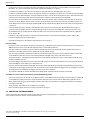
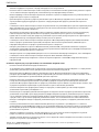
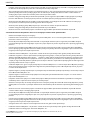
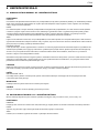
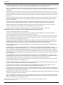
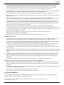
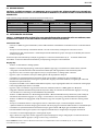
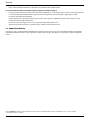
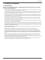
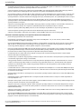
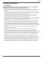
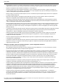
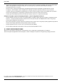
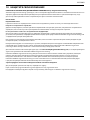
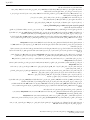
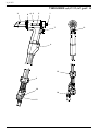
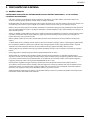
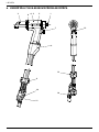
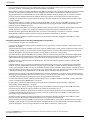
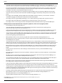
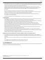
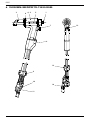
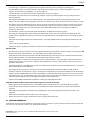
6. GENERAL ASSEMBLY OF INSTALLATION TOOL 73430-02000
34, 25 1
7
8
9
10
11
13
14
1
2
6
15
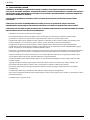
ENGLISH

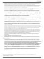
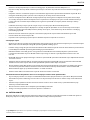
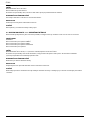
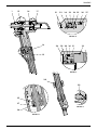
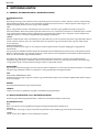
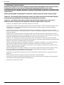
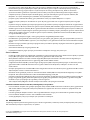
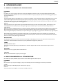
115161721 22 34 23 24 25 26 27
39
20
28 29 30 36 31 33
35
37
38
B
C
E
D
18
19
DETAIL B
DETAIL C
DETAIL D
DETAIL E
GENERAL ASSEMBLY OF INSTALLATION TOOL 73430-02000
16
ENGLISH

7. PARTS LIST FOR INSTALLATION TOOL 73430-02000
73430-02000 Parts List
ITEM PART NUMBER DESCRIPTION QTY.
1 73430-02003 PISTON 1
2 73430-02001 BODY 1
3 73430-02011 DEFLECTOR 1
4 73425-02016 SAFETY LABEL 1
5 73430-02026 AV10 LABEL 2
6 07007-01504 CE & UKCA LABEL 1
7 07007-02103 TRIGGER SWITCH 1
8 73430-02020 HANDLE GATOR 1
9 07001-00686 M4 X 16 SKT CAP HD SCREW 2
10 07005-10118 QUICK COUPLER – MALE 1
11 07005-10120 QUICK COUPLER – FEMALE 1
12 07001-00479 M4 X 4 SKT SET SCREW 1
13 73430-02023 HOSE CLAMP 1
14 07007-02105 CONTROL CABLE 1
15 73430-02004 FRONT SEAL GLAND 1
16 73430-02006 REAR SEAL GLAND 1
17 73430-02005 END CAP 1
18 07005-10119 HYDRAULIC HOSE – RETURN 1
19 07005-10117 HYDRAULIC HOSE – PULL 1
20 73430-02024 CLAMP INSERT 1
21 07003-00457 O-RING 1
22 07003-00440 WIPER SEAL 1
23 07003-00458 O-RING 1
24 73430-02009 FRONT BEARING RING 1
25 07003-00439 ROD SEAL 1
26 07003-00443 PISTON SEAL 1
27 07003-00444 ANTI-EXTRUSION RING 2
28 07003-00441 ROD SEAL 1
29 73430-02010 REAR BEARING RING 1
30 07003-00459 O-RING 1
31 07003-00442 WIPER SEAL 1
32
33 07003-00460 O-RING 1
34 07003-00492 SPIRAL BACK-UP RING 1
35 07007-02032 CABLE TIE 1
36 07003-00493 SPIRAL BACK-UP RING 1
37 07005-10121 PROTECTIVE SLEEVE 0.6 m
38 07007-02104 CABLE GLAND 1
39 73430-02008 TRIGGER INSERT 1
- 07900-01020 AV10 TOOL INSTRUCTION MANUAL 1
17
ENGLISH

8. SAFETY DATA
8.1 ENERPAC® HF HYDRAULIC OIL - SAFETY DATA
FIRST AID
SKIN:
Unlikely to cause harm to the skin on brief or occasional contact but prolonged or exposure may lead to dermatitis. Wash
skin thoroughly with soap and water as soon as reasonably practicable. Remove heavily contaminated clothing and wash
underlying skin.
ORAL:
Unlikely to cause harm if accidentally swallowed in small doses, though larger quantities may cause nausea and diarrhea.
If contamination of the mouth occurs, wash out thoroughly with water. Except as a deliberate act, the ingestion of large
amounts of product is unlikely. If it should occur, do not induce vomiting; obtain medical advice. Take person to nearest
medical centre.
EYES:
Unlikely to cause more than transient stinging or redness if accidental eye contact occurs. Wash eyes thoroughly with
copious quantities of water, ensuring eyelids are held open. Obtain medical advice if any pain or redness develops or
persists.
MEDICAL ADVICE:
Treatment should in general be symptomatic and directed to relieving any effects. Note: High Pressure Applications:
Injections through the skin, resulting from contact with the product at high pressure, constitute a major medical emergency.
Injuries may not appear serious at first but within a few hours tissue becomes swollen, discolored and extremely painful with
extensive subcutaneous necrosis.
Surgical exploration should be undertaken without delay. Thorough and extensive debridement of the wound and
underlying tissue is necessary to minimize tissue loss and prevent or limit permanent damage. Note that high pressure may
force the product considerable distances along tissue planes.
DISPOSAL
Remove all spills with inert absorbent material. Ventilate spill area. Place contaminated materials in a disposable container
and dispose in a manner consistent with local regulations.
FIRE
FLASH POINT: 200°C.
Extinguish with either dry chemical, foam or carbon dioxide. Do not enter confined space without self contained breathing
apparatus.
HANDLING
Use barrier cream or oil resistant gloves.
STORAGE
Undercover and consistent with local regulations for inflammable material.
8.2 MOLYLITHIUM GREASE EP 3753 - SAFETY DATA
Grease can be ordered as a single item, the part number is shown in the Service Kit page 11.
FIRST AID
SKIN:
As the grease is completely water resistant it is best removed with an approved emulsifying skin cleaner.
INGESTION:
Ensure the individual drinks 30ml Milk of Magnesia, preferably in a cup of milk.
EYES:
Irritant but not harmful. Irrigate with water and seek medical attention.
18
ENGLISH

FIRE
FLASH POINT: Above 220°C.
Not classified as flammable.
Suitable extinguishing media: CO2, Halon or water spray if applied by an experienced operator.
ENVIRONMENT
Scrape up for incineration or disposal on approved site.
HANDLING
Use barrier cream or oil resistant gloves
STORAGE
Away from heat and oxidising agent.
8.3 MOLYKOTE® 111 GREASE - SAFETY DATA
Grease can be ordered as a single item, the part number is shown in the Service Kit page 11.
FIRST AID
SKIN:
No first aid should be needed. INGESTION:
No first aid should be needed. EYES:
No first aid should be needed. INHALATION:
No first aid should be needed.
FIRE
FLASH POINT: Above 101.1°C. (closed cup) Explosive Properties: No
Suitable Extinguishing Media: Carbon Dioxide Foam, Dry Powder or fine water spray. Water can be used to cool fire exposed
containers.
ENVIRONMENT
No adverse effects are predicted.
HANDLING
General ventilation is recommended. Avoid eye contact.
STORAGE
Do not store with oxidizing agents. Keep container closed and store away from water or moisture
19
ENGLISH

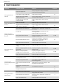
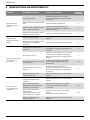
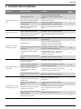
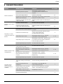
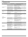
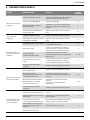
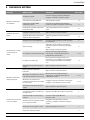
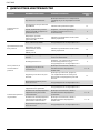
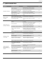
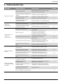
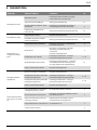
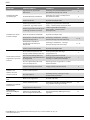
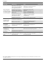
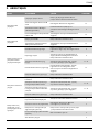
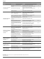
9. FAULT DIAGNOSIS
SYMPTOMPOSSIBLE CAUSE REMEDY PAGE REF.
Placing Tool will not
operate
Inoperative pump unit Check pump power supply and refer to
pump unit instruction manual
Faulty Quick Couplers 10 and 11 Replace Quick Couplers 14
Trigger Control Cable 14 not
connected correctly
Check Control Cable is correctly connected
at pump and placing tool 9
Damaged Trigger Switch 7 or
Control Cable 14
Replace Trigger Switch and/or Control
Cable 14
Trigger Switch 7 does not
function
Pump in local mode Refer to pump instruction manual
Trigger Switch 7, Control Cable
14 or connector damaged
Replace Trigger Switch and/or Control
Cable 14
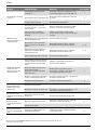
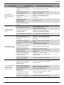
Pump running but
placing tools does not
function
Hydraulic Hoses not connected Check for correct connections at pump and
placing tool 9
Low oil level
Ensure placing tool is lled with oil and
correctly primed.
Refer to pump instruction manual
9
Placing tool external oil leak Inspect placing tool – replace worn or
damaged components 12–14
Hose Assembly external oil leak
Inspect Hose Assembly – ensure hose
connections are tight and/or replace
damaged hose connectors
14
Pump internal/external oil leak Refer to pump instruction manual
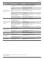
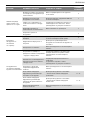
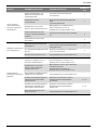
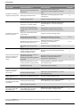
Placing tool operates
erratically
Low or erratic hydraulic pressure
supply Refer to pump instruction manual
Worn or damaged hydraulic seals in
placing tool
Inspect placing tool – replace worn or
damaged seals 12–14
Worn or damaged hydraulic
sealing surfaces in placing tool
Inspect placing tool – replace
worn or damaged components 12–14
Pump internal/external oil leak Refer to pump instruction manual
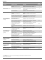
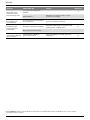
Pump builds full
pressure, but pintail does
not break
Breakload greater than placing tool
capacity at full pressure Refer to placing tool specication 6
Flow to placing tool blocked Check Quick Couplers 10 and 11
for full engagement 8
Pump pressure relief value set too
low
Adjust pressure relief valve settings – refer
to pump instruction manual
Pull grooves on fastener pintail
stripped See symptom on page 20 10
Improper tool operation 10
Placing tool Piston 1
will not return
Return ow restricted or blocked Check Quick Couplers 10 and 11 for full
engagement and/or fault 9
Hydraulic Hoses not connected Check for correct connections at pump and
placing tool 9
Pump valve malfunction Refer to pump instruction manual
20
ENGLISH
Sayfa yükleniyor...
Sayfa yükleniyor...
Sayfa yükleniyor...
Sayfa yükleniyor...
Sayfa yükleniyor...
Sayfa yükleniyor...
Sayfa yükleniyor...
Sayfa yükleniyor...
Sayfa yükleniyor...
Sayfa yükleniyor...
Sayfa yükleniyor...
Sayfa yükleniyor...
Sayfa yükleniyor...
Sayfa yükleniyor...
Sayfa yükleniyor...
Sayfa yükleniyor...
Sayfa yükleniyor...
Sayfa yükleniyor...
Sayfa yükleniyor...
Sayfa yükleniyor...
Sayfa yükleniyor...
Sayfa yükleniyor...
Sayfa yükleniyor...
Sayfa yükleniyor...
Sayfa yükleniyor...
Sayfa yükleniyor...
Sayfa yükleniyor...
Sayfa yükleniyor...
Sayfa yükleniyor...
Sayfa yükleniyor...
Sayfa yükleniyor...
Sayfa yükleniyor...
Sayfa yükleniyor...
Sayfa yükleniyor...
Sayfa yükleniyor...
Sayfa yükleniyor...
Sayfa yükleniyor...
Sayfa yükleniyor...
Sayfa yükleniyor...
Sayfa yükleniyor...
Sayfa yükleniyor...
Sayfa yükleniyor...
Sayfa yükleniyor...
Sayfa yükleniyor...
Sayfa yükleniyor...
Sayfa yükleniyor...
Sayfa yükleniyor...
Sayfa yükleniyor...
Sayfa yükleniyor...
Sayfa yükleniyor...
Sayfa yükleniyor...
Sayfa yükleniyor...
Sayfa yükleniyor...
Sayfa yükleniyor...
Sayfa yükleniyor...
Sayfa yükleniyor...
Sayfa yükleniyor...
Sayfa yükleniyor...
Sayfa yükleniyor...
Sayfa yükleniyor...
Sayfa yükleniyor...
Sayfa yükleniyor...
Sayfa yükleniyor...
Sayfa yükleniyor...
Sayfa yükleniyor...
Sayfa yükleniyor...
Sayfa yükleniyor...
Sayfa yükleniyor...
Sayfa yükleniyor...
Sayfa yükleniyor...
Sayfa yükleniyor...
Sayfa yükleniyor...
Sayfa yükleniyor...
Sayfa yükleniyor...
Sayfa yükleniyor...
Sayfa yükleniyor...
Sayfa yükleniyor...
Sayfa yükleniyor...
Sayfa yükleniyor...
Sayfa yükleniyor...
Sayfa yükleniyor...
Sayfa yükleniyor...
Sayfa yükleniyor...
Sayfa yükleniyor...
Sayfa yükleniyor...
Sayfa yükleniyor...
Sayfa yükleniyor...
Sayfa yükleniyor...
Sayfa yükleniyor...
Sayfa yükleniyor...
Sayfa yükleniyor...
Sayfa yükleniyor...
Sayfa yükleniyor...
Sayfa yükleniyor...
Sayfa yükleniyor...
Sayfa yükleniyor...
Sayfa yükleniyor...
Sayfa yükleniyor...
Sayfa yükleniyor...
Sayfa yükleniyor...
Sayfa yükleniyor...
Sayfa yükleniyor...
Sayfa yükleniyor...
Sayfa yükleniyor...
Sayfa yükleniyor...
Sayfa yükleniyor...
Sayfa yükleniyor...
Sayfa yükleniyor...
Sayfa yükleniyor...
Sayfa yükleniyor...
Sayfa yükleniyor...
Sayfa yükleniyor...
Sayfa yükleniyor...
Sayfa yükleniyor...
Sayfa yükleniyor...
Sayfa yükleniyor...
Sayfa yükleniyor...
Sayfa yükleniyor...
Sayfa yükleniyor...
Sayfa yükleniyor...
Sayfa yükleniyor...
Sayfa yükleniyor...
Sayfa yükleniyor...
Sayfa yükleniyor...
Sayfa yükleniyor...
Sayfa yükleniyor...
Sayfa yükleniyor...
Sayfa yükleniyor...
Sayfa yükleniyor...
Sayfa yükleniyor...
Sayfa yükleniyor...
Sayfa yükleniyor...
Sayfa yükleniyor...
Sayfa yükleniyor...
Sayfa yükleniyor...
Sayfa yükleniyor...
Sayfa yükleniyor...
Sayfa yükleniyor...
Sayfa yükleniyor...
Sayfa yükleniyor...
Sayfa yükleniyor...
Sayfa yükleniyor...
Sayfa yükleniyor...
Sayfa yükleniyor...
Sayfa yükleniyor...
Sayfa yükleniyor...
Sayfa yükleniyor...
Sayfa yükleniyor...
Sayfa yükleniyor...
Sayfa yükleniyor...
Sayfa yükleniyor...
Sayfa yükleniyor...
Sayfa yükleniyor...
Sayfa yükleniyor...
Sayfa yükleniyor...
Sayfa yükleniyor...
Sayfa yükleniyor...
Sayfa yükleniyor...
Sayfa yükleniyor...
Sayfa yükleniyor...
Sayfa yükleniyor...
Sayfa yükleniyor...
Sayfa yükleniyor...
Sayfa yükleniyor...
Sayfa yükleniyor...
Sayfa yükleniyor...
Sayfa yükleniyor...
Sayfa yükleniyor...
Sayfa yükleniyor...
Sayfa yükleniyor...
Sayfa yükleniyor...
Sayfa yükleniyor...
Sayfa yükleniyor...
Sayfa yükleniyor...
Sayfa yükleniyor...
Sayfa yükleniyor...
Sayfa yükleniyor...
Sayfa yükleniyor...
Sayfa yükleniyor...
Sayfa yükleniyor...
Sayfa yükleniyor...
Sayfa yükleniyor...
Sayfa yükleniyor...
Sayfa yükleniyor...
Sayfa yükleniyor...
Sayfa yükleniyor...
Sayfa yükleniyor...
Sayfa yükleniyor...
Sayfa yükleniyor...
Sayfa yükleniyor...
Sayfa yükleniyor...
Sayfa yükleniyor...
Sayfa yükleniyor...
Sayfa yükleniyor...
Sayfa yükleniyor...
Sayfa yükleniyor...
Sayfa yükleniyor...
Sayfa yükleniyor...
Sayfa yükleniyor...
Sayfa yükleniyor...
Sayfa yükleniyor...
Sayfa yükleniyor...
Sayfa yükleniyor...
Sayfa yükleniyor...
Sayfa yükleniyor...
Sayfa yükleniyor...
Sayfa yükleniyor...
Sayfa yükleniyor...
Sayfa yükleniyor...
Sayfa yükleniyor...
Sayfa yükleniyor...
Sayfa yükleniyor...
Sayfa yükleniyor...
Sayfa yükleniyor...
Sayfa yükleniyor...
Sayfa yükleniyor...
Sayfa yükleniyor...
Sayfa yükleniyor...
Sayfa yükleniyor...
Sayfa yükleniyor...
Sayfa yükleniyor...
Sayfa yükleniyor...
Sayfa yükleniyor...
Sayfa yükleniyor...
Sayfa yükleniyor...
Sayfa yükleniyor...
Sayfa yükleniyor...
Sayfa yükleniyor...
Sayfa yükleniyor...
Sayfa yükleniyor...
Sayfa yükleniyor...
Sayfa yükleniyor...
Sayfa yükleniyor...
Sayfa yükleniyor...
Sayfa yükleniyor...
Sayfa yükleniyor...
Sayfa yükleniyor...
Sayfa yükleniyor...
Sayfa yükleniyor...
Sayfa yükleniyor...
Sayfa yükleniyor...
Sayfa yükleniyor...
Sayfa yükleniyor...
Sayfa yükleniyor...
Sayfa yükleniyor...
Sayfa yükleniyor...
Sayfa yükleniyor...
Sayfa yükleniyor...
Sayfa yükleniyor...
Sayfa yükleniyor...
Sayfa yükleniyor...
Sayfa yükleniyor...
Sayfa yükleniyor...
Sayfa yükleniyor...
Sayfa yükleniyor...
Sayfa yükleniyor...
Sayfa yükleniyor...
Sayfa yükleniyor...
Sayfa yükleniyor...
Sayfa yükleniyor...
Sayfa yükleniyor...
Sayfa yükleniyor...
Sayfa yükleniyor...
Sayfa yükleniyor...
Sayfa yükleniyor...
Sayfa yükleniyor...
Sayfa yükleniyor...
Sayfa yükleniyor...
Sayfa yükleniyor...
Sayfa yükleniyor...
Sayfa yükleniyor...
Sayfa yükleniyor...
Sayfa yükleniyor...
Sayfa yükleniyor...
Sayfa yükleniyor...
Sayfa yükleniyor...
Sayfa yükleniyor...
Sayfa yükleniyor...
Sayfa yükleniyor...
Sayfa yükleniyor...
Sayfa yükleniyor...
Sayfa yükleniyor...
Sayfa yükleniyor...
Sayfa yükleniyor...
Sayfa yükleniyor...
Sayfa yükleniyor...
Sayfa yükleniyor...
Sayfa yükleniyor...
Sayfa yükleniyor...
Sayfa yükleniyor...
Sayfa yükleniyor...
Sayfa yükleniyor...
Sayfa yükleniyor...
Sayfa yükleniyor...
Sayfa yükleniyor...
Sayfa yükleniyor...
Sayfa yükleniyor...
Sayfa yükleniyor...
Sayfa yükleniyor...
Sayfa yükleniyor...
Sayfa yükleniyor...
Sayfa yükleniyor...
Sayfa yükleniyor...
Sayfa yükleniyor...
Sayfa yükleniyor...
Sayfa yükleniyor...
Sayfa yükleniyor...
Sayfa yükleniyor...
Sayfa yükleniyor...
Sayfa yükleniyor...
Sayfa yükleniyor...
Sayfa yükleniyor...
Sayfa yükleniyor...
Sayfa yükleniyor...
Sayfa yükleniyor...
Sayfa yükleniyor...
Sayfa yükleniyor...
Sayfa yükleniyor...
Sayfa yükleniyor...
Sayfa yükleniyor...
Sayfa yükleniyor...
Sayfa yükleniyor...
Sayfa yükleniyor...
Sayfa yükleniyor...
Sayfa yükleniyor...
Sayfa yükleniyor...
Sayfa yükleniyor...
Sayfa yükleniyor...
Sayfa yükleniyor...
Sayfa yükleniyor...
Sayfa yükleniyor...
Sayfa yükleniyor...
Sayfa yükleniyor...
Sayfa yükleniyor...
Sayfa yükleniyor...
Sayfa yükleniyor...
Sayfa yükleniyor...
Sayfa yükleniyor...
Sayfa yükleniyor...
Sayfa yükleniyor...
Sayfa yükleniyor...
Sayfa yükleniyor...
Sayfa yükleniyor...
Sayfa yükleniyor...
Sayfa yükleniyor...
Sayfa yükleniyor...
Sayfa yükleniyor...
Sayfa yükleniyor...
-
 1
1
-
 2
2
-
 3
3
-
 4
4
-
 5
5
-
 6
6
-
 7
7
-
 8
8
-
 9
9
-
 10
10
-
 11
11
-
 12
12
-
 13
13
-
 14
14
-
 15
15
-
 16
16
-
 17
17
-
 18
18
-
 19
19
-
 20
20
-
 21
21
-
 22
22
-
 23
23
-
 24
24
-
 25
25
-
 26
26
-
 27
27
-
 28
28
-
 29
29
-
 30
30
-
 31
31
-
 32
32
-
 33
33
-
 34
34
-
 35
35
-
 36
36
-
 37
37
-
 38
38
-
 39
39
-
 40
40
-
 41
41
-
 42
42
-
 43
43
-
 44
44
-
 45
45
-
 46
46
-
 47
47
-
 48
48
-
 49
49
-
 50
50
-
 51
51
-
 52
52
-
 53
53
-
 54
54
-
 55
55
-
 56
56
-
 57
57
-
 58
58
-
 59
59
-
 60
60
-
 61
61
-
 62
62
-
 63
63
-
 64
64
-
 65
65
-
 66
66
-
 67
67
-
 68
68
-
 69
69
-
 70
70
-
 71
71
-
 72
72
-
 73
73
-
 74
74
-
 75
75
-
 76
76
-
 77
77
-
 78
78
-
 79
79
-
 80
80
-
 81
81
-
 82
82
-
 83
83
-
 84
84
-
 85
85
-
 86
86
-
 87
87
-
 88
88
-
 89
89
-
 90
90
-
 91
91
-
 92
92
-
 93
93
-
 94
94
-
 95
95
-
 96
96
-
 97
97
-
 98
98
-
 99
99
-
 100
100
-
 101
101
-
 102
102
-
 103
103
-
 104
104
-
 105
105
-
 106
106
-
 107
107
-
 108
108
-
 109
109
-
 110
110
-
 111
111
-
 112
112
-
 113
113
-
 114
114
-
 115
115
-
 116
116
-
 117
117
-
 118
118
-
 119
119
-
 120
120
-
 121
121
-
 122
122
-
 123
123
-
 124
124
-
 125
125
-
 126
126
-
 127
127
-
 128
128
-
 129
129
-
 130
130
-
 131
131
-
 132
132
-
 133
133
-
 134
134
-
 135
135
-
 136
136
-
 137
137
-
 138
138
-
 139
139
-
 140
140
-
 141
141
-
 142
142
-
 143
143
-
 144
144
-
 145
145
-
 146
146
-
 147
147
-
 148
148
-
 149
149
-
 150
150
-
 151
151
-
 152
152
-
 153
153
-
 154
154
-
 155
155
-
 156
156
-
 157
157
-
 158
158
-
 159
159
-
 160
160
-
 161
161
-
 162
162
-
 163
163
-
 164
164
-
 165
165
-
 166
166
-
 167
167
-
 168
168
-
 169
169
-
 170
170
-
 171
171
-
 172
172
-
 173
173
-
 174
174
-
 175
175
-
 176
176
-
 177
177
-
 178
178
-
 179
179
-
 180
180
-
 181
181
-
 182
182
-
 183
183
-
 184
184
-
 185
185
-
 186
186
-
 187
187
-
 188
188
-
 189
189
-
 190
190
-
 191
191
-
 192
192
-
 193
193
-
 194
194
-
 195
195
-
 196
196
-
 197
197
-
 198
198
-
 199
199
-
 200
200
-
 201
201
-
 202
202
-
 203
203
-
 204
204
-
 205
205
-
 206
206
-
 207
207
-
 208
208
-
 209
209
-
 210
210
-
 211
211
-
 212
212
-
 213
213
-
 214
214
-
 215
215
-
 216
216
-
 217
217
-
 218
218
-
 219
219
-
 220
220
-
 221
221
-
 222
222
-
 223
223
-
 224
224
-
 225
225
-
 226
226
-
 227
227
-
 228
228
-
 229
229
-
 230
230
-
 231
231
-
 232
232
-
 233
233
-
 234
234
-
 235
235
-
 236
236
-
 237
237
-
 238
238
-
 239
239
-
 240
240
-
 241
241
-
 242
242
-
 243
243
-
 244
244
-
 245
245
-
 246
246
-
 247
247
-
 248
248
-
 249
249
-
 250
250
-
 251
251
-
 252
252
-
 253
253
-
 254
254
-
 255
255
-
 256
256
-
 257
257
-
 258
258
-
 259
259
-
 260
260
-
 261
261
-
 262
262
-
 263
263
-
 264
264
-
 265
265
-
 266
266
-
 267
267
-
 268
268
-
 269
269
-
 270
270
-
 271
271
-
 272
272
-
 273
273
-
 274
274
-
 275
275
-
 276
276
-
 277
277
-
 278
278
-
 279
279
-
 280
280
-
 281
281
-
 282
282
-
 283
283
-
 284
284
-
 285
285
-
 286
286
-
 287
287
-
 288
288
-
 289
289
-
 290
290
-
 291
291
-
 292
292
-
 293
293
-
 294
294
-
 295
295
-
 296
296
-
 297
297
-
 298
298
-
 299
299
-
 300
300
-
 301
301
-
 302
302
-
 303
303
-
 304
304
-
 305
305
-
 306
306
-
 307
307
-
 308
308
-
 309
309
-
 310
310
-
 311
311
-
 312
312
-
 313
313
-
 314
314
-
 315
315
-
 316
316
-
 317
317
-
 318
318
-
 319
319
-
 320
320
-
 321
321
-
 322
322
-
 323
323
-
 324
324
-
 325
325
-
 326
326
-
 327
327
-
 328
328
-
 329
329
-
 330
330
-
 331
331
-
 332
332
-
 333
333
-
 334
334
-
 335
335
-
 336
336
-
 337
337
-
 338
338
-
 339
339
-
 340
340
-
 341
341
-
 342
342
-
 343
343
-
 344
344
-
 345
345
-
 346
346
-
 347
347
-
 348
348
-
 349
349
-
 350
350
-
 351
351
-
 352
352
-
 353
353
-
 354
354
-
 355
355
-
 356
356
-
 357
357
-
 358
358
-
 359
359
-
 360
360
-
 361
361
-
 362
362
-
 363
363
-
 364
364
-
 365
365
-
 366
366
-
 367
367
-
 368
368


diğer dillerde
- eesti: Stanley AV10 Kasutusjuhend
- slovenčina: Stanley AV10 Používateľská príručka
- română: Stanley AV10 Manual de utilizare