
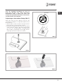
stampa_cop_indesit 11-02-2008 9:34 Pagina 1


I
3
Indice
Istruzioni per l’utente
Installazione, 4
Uso, 4
Manutenzione, 4
Istruzioni per l’installatore
Installazione, 6
Collegamento gas, 6
Collegamento elettrico, 6
Caratteristiche utilizzatori, 7
Assistenza, 8
QUESTO PRODOTTO È STATO CONCEPITO
PER UN IMPIEGO DI TIPO DOMESTICO. IL
COSTRUTTORE DECLINA OGNI RESPON-
SABILITÀ NEL CASO DI EVENTUALI DANNI
A COSE O PERSONE DERIVANTI DA UNA
NON CORRETTA INSTALLAZIONE O DA USO
IMPROPRIO, ERRONEO OD ASSURDO.
I
Italiano
I
English
GB
Français
FR
Deutsch
DE
Español
Persian
ES
IR
Português
PT
TR
AR
Caro Cliente,
sentitamente La ringraziamo e ci congratuliamo
per la scelta da Lei fatta. Questo nuovo
prodotto, accuratamente progettato e costruito
con materiali di primissima qualità, è stato
accuratamente collaudato per poter soddisfare
tutte le Sue esigenze di una perfetta cottura.
La preghiamo pertanto di leggere e rispettare
le facili istruzioni che Le permetteranno di
raggiungere eccellenti risultati sin dalla prima
utilizzazione. Con questo moderno apparecchio
Le formuliamo i nostri più vivi auguri.
IL COSTRUTTORE
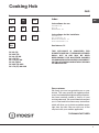
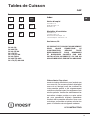
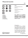
Piano di Cottura
GAS
DP 2G (IX)
DP 2GS (IX)
DP 2G (IX) GH
DP 1TC (IX)
DP 1TC (IX) GH
DP 2G (IX)AG
DP 2GS (IX) AUS
DP 1TC (IX) GH AUS
ϱΰϴϠϜϧ
ϲδϧήϓ
·ϲϧΎΒγ
͂ΎϐΗήΑ
ϲΑήϋ
ϲγέΎϓ
RU
Türkçe

I
4
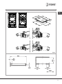
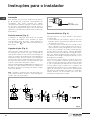
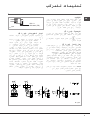
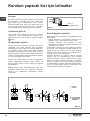
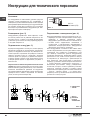
Gas
Fig.1
corona Ø 20-32
rapido Ø 20-26
ausiliario Ø 10-14
Manutenzione Gas/Elettrico
Prima di ogni operazione disinserire elettricamente
l’apparecchiatura.
Per una maggiore durata dell’apparecchiatura è
indispensabile eseguire periodicamente un’accurata
pulizia generale tenendo presente quanto segue:
- le partiin vetro, acciaio e/o smaltate devono essere
pulite con prodottiidonei (reperibili in commercio)
non abrasivi o corrosivi. Evitare prodotti a base di
cloro (varechina, ecc.) evitare di lasciare sul piano
lavoro sostanze acide o alcaline (aceto, sale, succo
di limone, ecc.)
- gli spartifiamma ed icoperchietti (parti mobili del
bruciatore) vanno frequentemente lavati con acqua
bollente e detersivo avendo cura di togliere ogni
eventuale incrostazione, asciugati accuratamente,
controllare che nessuno dei fori dello spartifiamma
risulti otturato anche parzialmente.
- le griglie inox del piano di lavoro dopo essere state
riscaldate assumono una colorazione bluastra che
non ne deteriora la qualità. Per riportarle all’aspetto
originale usare un prodotto legger-mente abrasivo.
N.B. - L’eventuale lubrificazione dei rubinetti deve
essere eseguita da personale qualificato al quale è
bene rivolgersiin caso di anomalie di funzionamento.
Controllare periodicamente lo stato di conservazione
del tubo flessibile dialimentazione gas. In caso di
perdite richiedere l’immediato intervento del personale
qualificato per la sostituzione.
NON UTILIZZARE PULITORI A VAPORE
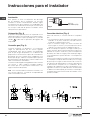
Installazione
Tutte le operazioni relative all’installazione (allacciamento
elettrico, allacciamento gas, adattamento al tipo di gas,
conseguenti regolazioni, ecc.) devono essere eseguite
da personale qualificato secondo le norme vigenti.
Per le istruzioni specifiche vedi la parte riservata
all’installatore.
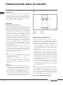
Uso
Bruciatori gas (Fig. 1-3).
L’accensione del bruciatore avviene avvicinando una
fiammella ai fori della parte superiore dello stesso
premendo e ruotando in senso antiorario la ma-nopola
corrispondente sino a farne coincidere l’indice con
la posizione di massimo. Ad accensione avvenuta
regolare la fiamma secondo la necessità. La posizione
di minimo si trova al termine delle rotazione antioraria.
Nei modelli con accensione automatica agire sulla
manopola come sopra descritto, premendo con-
temporaneamente l’apposito pulsante. Nei modelli
con accensione automatica/ simultanea (a una
mano) è sufficiente agire come sopra descritto sulla
sola manopola corrispondente. La scarica elettrica
fra candelina e bruciatore dà luogo all’accensione
del bruciatore interessato. Ad accensione avvenuta
rilasciare immediatamente il pulsante regolando la
fiamma secondo necessità. L’accensione del bruciatore
nei modelli con sicurezza termoelettrica avviene come
nei diversi casi sopra descritti tenendo premuta a fondo
la manopola nella posizione di massimo per circa 3/5
secondi. Nel rilasciare la manopola assicurarsi che il
bruciatore rimanga acceso.
N.B.:
- si consiglia di usare pentole di diametro adatto
ai bruciatori evitando che la fiamma al massimo
fuoriesca dal fondo delle stesse
- non lasciare pentole vuote sul fuoco acceso
- sui piani Crystal non usare accessori di cottura
alla griglia. Al termine della cottura è buona norma
provvedere anche alla chiusura del rubinetto
principale del condotto e/o della bombola.
Importante
a) nei piani con sicurezza termoelettrica non azionare
l’accensione oltre 15 secondi. Se dopo 15 secondi il
bruciatore non si è acceso, aprire la porta del locale
e attendere almeno un minuto prima di ritentare.
b) nei piani senza sicurezza in caso di estinzione
delle fiamme di un bruciatore chiudere il rubinetto
corrispondente e non ritentare l’accensione prima di
un minuto.
Istruzioni per l’utente

I
5
Fig. 2

I
6
ISO 7/1
ISO 228/1 (FR)
Fig. 3
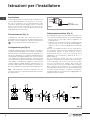
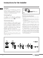
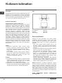
Collegamento elettrico (Fig. 4)
Prima di effettuare l’allacciamento elettrico accertarsi che:
• lecaratteristichedell’impiantosianotalidasoddisfare
quanto indicato sulla targa matricola applicata sul
fondo del piano;
• l’impianto sia munito diun efcace collegamento di
terra secondo le norme e le disposizionidi legge in
vigore. La messa a terra è obbligatoria a termini di
legge.
Nel caso che l’apparecchiatura non sia munita dicavo
e/o di relativa spina utilizzare materiale idoneo per
l’assorbimento indicato in targa matricola e per la
temperatura di lavoro. Il cavo in nessun punto dovrà
raggiungere una temperatura superiore di 50 °C a
quella ambiente.
Per il collegamento diretto alla rete è necessario
interporre un interruttore omnipolare dimensionato per
il carico di targa che assicuri la sconnessione della
rete con una distanza di apertura dei contatti che
consenta la disconnessione completa nelle condizioni
della categoria di sovratensione III, conformemente
alle regole di installazione (il cavo di terra giallo/verde
non deve essere interrotto). La presa o l’interruttore
omnipolare devono essere facilmente reggiungibili con
l’apparecchiatura installata.
Installazione
Questo apparecchio non è provvisto di un dispositivo di
scarico del prodotti della com-bustione. Si raccoman-
da che sia installato in locali sufficientemente areati
secondo le di-sposizioni di legge vi-genti. La quantità
d’aria necessaria alla combustione non deve essere
inferiore a 2.0 m
3
/h per ogni kW dipotenza installato.
Vedi tabella potenze bruciatori.
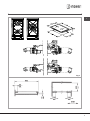
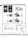
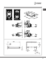
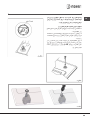
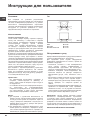
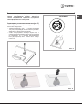
Posizionamento (Fig. 2)
L’apparecchio è previsto per essere incas-sato in un
piano dilavoro come illustrato nell’apposita figura.Prima
diinserire il piano predisporre la guarnizione di tenuta
X
su tutto il perimetro della foratura d’incasso.
Collegamento gas (Fig. 3)
Collegare l’apparecchiatura alla bombola o all’impianto
secondo le prescrizionidelle norme in vigore accertandosi
preventivamente che l’apparecchiatura sia predisposta al
tipo di gas disponibile. Le condizioni di predisposizione
sono riportate sulla targhetta apparecchio. In caso contrario
vedi: “Adattamento a diverso tipo di gas”. Verificare inoltre
che la pressione di alimentazione rientri nei valoririportati
nella tabella: “Caratteristiche utilizzatori”. Allacciamento
metallico rigido/semirigido Eseguire l’allacciamento con
raccordi e tubi metallici (anche flessibili) in modo da non
provocare sollecitazioni agli organiinterni all’apparecchio.
N.B. - Ad installazione ultimata controllare, con una
soluzione saponosa, la perfetta tenuta di tutto il sistema
di collegamento.
Istruzioni per l’installatore
Fig. 4

I
7
Se il cavo di alimentazione è danneggiato, esso deve
essere sostituito dal costruttore o dal suo servizio
assistenza tecnica o comunque da una persona
con qualifica similare, in modo da prevenire ogni
rischio.
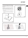
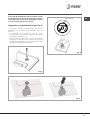
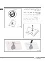
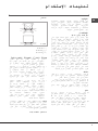
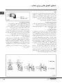
Adattamento a diverso tipo di gas (Fig. 5)
Se l’apparecchiatura risulta predisposta per un diverso
tipo di gas da quello di alimentazione disponibile, si
deve procedere:
• alla sostituzione degli iniettori (Fig. 5) con i
corrispondenti al tipo di gas da utilizzare (vedi tabella
“Caratteristiche utilizzatori”)
• per la regolazione del minimoagire con opportuno
cacciavite sulla vite posta sul rubinetto (Fig. 6)
dopo averlo ruotato in posizione di minimo. Per GPL
(butano/propano) avvitare a fondo.
Fig. 6
solo corona C3
Fig. 5
Fig. 6

I
8
La Casa costruttrice declina ogni responsabilità per le possibili inesattezze contenute nel presente opuscolo, imputabili
ad errori di stampa o di trascrizione. Si riserva il diritto di apportare ai propri prodotti quelle modifiche che ritiene
necessarie o utili, senza pregiudicare le carratteristiche essenziali.
Assistenza
Prima di contattare il Servizio di Assistenza Tecnica:
1. Verificare se non è possibile eliminare da soli i guasti.
2.
Riavviare il prodotto per accertarsi che l’inconveniente
sia stato ovviato. Se il risultato è negativo, disinserire
nuovamente il prodotto e ripetere l’operazione dopo un’ora.
3. Se il problema persiste, contattare il Servizio
Assistenza Tecnica.
Comunicare:
• iltipodiguasto,
• ilmodello,
• IlnumeroService(lacifrachesitrovadopolaparola
SERVICE sulla targhetta matricola posta sul retro del
prodotto)
• ilproprioindirizzocompleto,
• ilproprionumeroepressotelefonico.
Queste ultime informazioni si trovano sulla targhetta
caratteristiche posta sull’apparecchio.
Assistenza Attiva 7 giorni su 7
In caso di necessità d’intervento chiamate il Numero
Unico Nazionale 199.199.199*. Un operatore sarà a
completa disposizione per fissare un appuntamento
con il Centro Assistenza Tecnico Autorizzato più vicino
al luogo da cui si chiama. È attivo 7 giorni su 7, sabato
e domenica compresi, e non lascia mai inascoltata una
richiesta.
* Il costo della telefonata è di 14,25 centesimi di Euro al
minuto (iva inclusa) dal lunedì al venerdì dalle ore 8.00
alle ore 18.00, ed il sabato dalle ore
8.00 alle ore 13.00; e di 5,58 centesimi di Euro al
minuto (iva inclusa) dal lunedì al venerdì dalle 18.00
alle 08.00, ed il sabato dalle 13.00 alle 08.00 e i giorni
festivi, per chi chiama da telefono fisso. Per chi chiama
da cellulare il costo è legato all’operatore telefonico
utilizzato. Le suddette tariffe potrebbero essere
soggette a variazione da parte dell’operatore telefonico
utilizzato, per maggiori informazioni consultare il sito
www.indesitcompany.com.
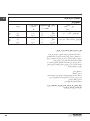
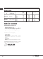
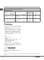
CARATTERISTICHE UTILIZZATORI
BRUCIATORI GAS
ALIMENTAZIONE BRUCIATORE Ø INIETTORI
PORTATA TERMICA
TIPO
PRESSIONE mbar
NOMINALE CONSUMO
NORM. 1/100 mm W
gas naturale G20 20
rapido 129 3000 286
l/h
ausiliario 77 1000 95
corona 3 141 3500 333
gas liquido
G30/G31 28-30/37
rapido 87 3000 218
g/h
ausiliario 50 1000 73
corona 3 94 3500 254
G110
gas città
G110/G140 8
rapido 320/340 3000 680/711
l/h
ausiliario 150/160 1000 227/237
corona 3 350 4000 907/949

9
GB
Index
Instructions for use
Installation, 10
Use, 10
Maintenance, 10
Instructions for the installater
Installation, 12
Gas connection, 12
Electrical connection, 12
User characteristics, 13
Assistance, 14
THIS APPLIANCE IS CONCEIVED FOR
DOMESTIC USE ONLY. THE MANUFACTURER
SHALL NOT IN ANY WAY BE HELD
RESPONSIBLE FOR WHATEVER INJURIES
OR DAMAGES ARE CAUSED BY INCORRECT
INSTALLATION OR BY UNSUITABLE, WRONG
OR ABSURD USE.
Dear customer,
We thank you and con-gratulate you on your
choice. This new carefully de-signed product,
manu-factured with the highest quality materials,
has been carefully tested to satisfy all your
cooking demands. We would therefore request
you to read and follow these easy instructions
which will allow you to obtain ex-cellent results
right from the start. May we wish you all the
very best with your modern appliance!
THE MANUFACTURER
Cooking Hob
GAS
DP 2G (IX)
DP 2GS (IX)
DP 2G (IX) GH
DP 1TC (IX)
DP 1TC (IX) GH
DP 2G (IX)AG
DP 2GS (IX) AUS
DP 1TC (IX) GH AUS
I
Italiano
I
English
GB
Français
FR
Deutsch
DE
Español
Persian
ES
IR
Português
PT
AR
ϱΰϴϠϜϧ
ϲδϧήϓ
·ϲϧΎΒγ
͂ΎϐΗήΑ
ϲΑήϋ
ϲγέΎϓ
Türkçe
TR
RU

10
GB
Gas
Fig.1
wok Ø 20-32
fast Ø 20-26
auxiliary Ø 10-14
Maintenance Gas/Electrical
Prior to any operation, disconnect the appliance from
theelectricalsystem.Forlong-lifetotheequipment,a
general cleaning operation must take place periodically,
bearing in mind the following:
- the glass, steel and/or enamelled parts must be
cleaned with suitable non-abrasive or corrosive
products (found on the market). Avoid chlorine-base
products (bleach, etc.);
- avoid leaving acid or alkaline substances on the
working area (vinegar, salt, lemon juice, etc.).
- the wall baffle and the small covers (mobile parts of
the burner) must be washed frequently with boiling
water and detergent, taking care to remove every
possible encrustation. Dry carefully and check that
none of the burner holes is fully or partially clogged;
- the stainless steel grids of the working area, after
having been heated, take on a bluish tint which does
not deteriorate the quality. To bring colour back to its
original state, use a slightly abrasive product.
N.B. - Cleaning of the taps must be carried out by
qualified personnel, who must be consulted in case of
any functioning anomaly. Check periodically the state
of conservation of the flexible gas feed pipe. In case of
leakage, call immediately the qualified technicians for
its replacement.
DO NOT USE STEAM CLEANERS
Installation
All the operations concerned with the installation
(electrical and gas connections, adaptation to type of
gas, necessary adjustments, etc.) must be carried out by
qualified technicians, in terms with the standards in force.
Forspecicinstructions,kindlyreadthepartreservedfor
the installation technician.
Use
Gas burners (Fig. 1-3).
The ignition of the gas burner is carried out by putting a
small flame to the upper part holes of the burner, pressing
and rotating the corresponding knob in an anti-klockwise
manner, until the maximum position has coincided with
the marker. When the gas burner has been turned
on, adjust the flame according to need. The minimum
position is found at the end of the anticlockwise rotation
direction. In models with automatic ignition, operate the
knob as described above, pressing simultaneously, the
correspondingpushbutton.Formodelswithautomatic/
simultaneous (with one hand) ignition, it is sufficient to
proceed as described above using the corresponding
knob. The electric spark between the ignition plug and
the burner provides the ignition of the burner itself.
After ignition, immediately release the push-button and
adjusttheameaccordingtoneed.Formodelswitha
thermoelectric safety system, the burner is ignited as in
the various cases described above, keeping the knob
fully pressed on the maximum position for approximately
3/5 seconds. After releasing the knob, make sure the
burner is actually lit.
N.B.:
- we recommend the use of pots and pans with a
diameter matching that of the burner, thus preventing
the flame from escaping from the bottom part and
surrounding the pot
- do not leave any empty pots or pans on the fire
- do not use any tools for grill-cooking on Crystal hobs.
When cooking is finished, it is also a good norm to
close the main gas pipe tap and/ or cylinder.
Important
a) on floors with thermoelectric protection do not keep
the ignite button pushed for more than 15 seconds.
If the burner has not ignited after 15 seconds, open
the door of the room and wait at least one minute
before making a further attempt.
b) on floors without protection, should the burner flame go
out close the corresponding gas cock and wait at least
one minute before making any attempt to ignite it.
Instructions for use

11
GB
Fig. 2

12
GB
ISO 7/1
ISO 228/1 (FR)
Fig. 3
Electrical connection (Fig. 4)
Prior to carrying out the electrical connection, please
ensure that:
• theplantcharacteristicsaresuchastofollowwhatis
indicated on the matrix plate placed at the bottom of
the working area;
• thattheplantisttedwithanefcientearthconnection,
following the standards and law provisions in force.
The earth connection is compulsory in terms of the
law.
Should there be no cable and/or plug on the
equipment, use suitable absorption material for the
working temperature as well, as indicated on the matrix
plate. Under no circumstance must the cable reach a
temperature above 50°C of the ambient tempera-ture.
If connecting directly to the mains power supply,
fit a multi-pole switch of a suitable size for the rated
capacity with a clearance distance which completely
disconnects the power line under overvoltage category
III conditions, consistently with the rules of installation
(the yellow/green earth wir must not be interrupted).
The plug or omnipolar switch must be easily reached
on the installed equipment.
Installation
This appliance is not provided with a combu-stion
product discharge. It is recommended that it be
installed in sufficiently aerated places, in terms of the
laws in force. The quantity of air which is necessary for
combu-stion must not be below 2.0 m
3
/h for each kW of
installed power. See table of burner power.
Positioning (Fig. 2)
The appliance can be fitted into a working area
as illustrated on the corresponding figure. Before
positioning the hob, fit the seal
X
around the entire
periphery of the hole cut in the worktop.
Gas connection (Fig. 3)
Connect the appliance to the gas cylinder or to the
installation according to the prescribed standards
in force, and ensure beforehand, that the appliance
matches the type of gas available. The type of gas
for which the appliance is predisposed is shown on
the appliance identification plate. Otherwise, see
“Adaptation to various types of gas”. Furthermore,
check that the feed pressure falls within the values
described on the table: “User chacteristics”.
Rigid/semi rigid metal connection Carry out the
connection with fittings and metal pipes (even flexible
pipes) so as to obtain counter stress the inner parts of
the appliance.
N.B. - when the installation has been carried out, check
the perfect sealing of the entire connection system, by
using a soapy solution.
Fig. 4
Instructions for the installer

13
GB
To avoid all risk, if the power cable becomes damaged,
it must only be replaced by the manufacturer,
by an authorised service centre, or by a qualified
electrician.
Adaptation to various types of gas (Fig. 5)
Should the appliance be pre-set for a different type of
gas than that available, proceed as follows:
• replacetheinjectors(Fig.5)withthecorresponding
type of gas to be used (see table “Uses
characteristics”).
• toadjustto the minimum,usea screwdriveronthe
screwplacedonthetap(Fig.6)afterturningthetap
to its minimum position. For LPG (butane/propane)
screw tight
Fig. 6
wok C3 only
Fig. 5
Fig. 6

14
GB
The manufacturer declines all responsibility for possible inaccuracies contained in this pamphlet, due to printing or
copying errors. We reserve the right to make on our own products those changes to be considered necessary or useful,
without jeopardizing the essential characteristics.
Assistance
Before contacting After-Sales Service:
1. See if you can solve the problem yourself.
2. Switch the appliance on again to see if the problem
has been solved. if it has not, disconnect the
appliance from the power supply and wait for about
an hour before switching on again.
3. If the problem persists after this course of action,
contact After-Sales Service.
Specify:
• thenatureofthefault,
• themodel
• the service number (the number after the word
SERVICE on the rating plate on the rear of the
appliance)
• yourfulladdress,
• yourtelephonenumberandareacode.
Never call on unauthorized technicians and always
refuse to purchase non-original spare parts.
USER CHARACTERISTICS
GAS BURNERS
FEED BURNER Ø INJECTORS
THERMAL CAPACITY
TYPE
PRESSURE mbar
NOMINAL
CONSUMPTION
NORM. 1/100 mm W
natural gas G20 20
fast 129 3000 286
l/h
auxiliary 77 1000 95
wok 3 141 3500 333
liquefied gas
G30/G31 28-30/37
fast 87 3000 218
g/h
auxiliary 50 1000 73
wok 3 94 3500 254

15
FR
Index
Notice d’emploi
Installation, 16
Mode d’emploi, 16
Entretien, 16
Modalités d’installation
Installation, 18
Connexion gaz, 18
Branchement électrique, 18
Caractéristiques utilisateurs, 19
Assistance, 20
CE PRODUIT EST CONÇU EXCLUSIVEMENT
POUR USAGE DOMESTIQUE. LE
CONSTRUCTEUR DÉCLINE TOUTE
RESPONSABILITÉ POUR DOMMAGES
ET BLESSURES CAUSÉES PAR UNE
INSTALLATION INCORRECTE OU PAR UN
USAGE IMPROPRE, ERRONÉ OU ABSURDE.
Français
FR
Chère cliente, Cher client,
merci et sincères félicitations pour le choix que
vous avez fait. Ce nouveau produit, développé
avec soin et fabriqué avec des matières de
toute première qualité, a été soigneusement
rodé pour satisfaire toutes Vos exigences d’une
cuisson parfaite. Veuillez lire attentivement les
instructions simples portées sur cette notice
qui vous permettront d’obtenir d’excellents
résultats dès la première utilisation. Nous vous
souhaitons une entière et pleine satisfac-tion
quant à l’utilisation de cet appareil moderne.
LE CONSTRUCTEUR
Tables de Cuisson
GAZ
DP 2G (IX)
DP 2GS (IX)
DP 2G (IX) GH
DP 1TC (IX)
DP 1TC (IX) GH
DP 2G (IX)AG
DP 2GS (IX) AUS
DP 1TC (IX) GH AUS
I
Italiano
I
English
GB
Deutsch
DE
Español
Persian
ES
IR
Português
PT
AR
ϱΰϴϠϜϧ
ϲδϧήϓ
·ϲϧΎΒγ
͂ΎϐΗήΑ
ϲΑήϋ
ϲγέΎϓ
Türkçe
TR
RU

16
FR
Gaz
Fig.1
wok Ø 20-32
rapide Ø 20-26
auxiliaire Ø 10-14
Entretien Gaz/Électric
Avant de toute opèration, débrancher l’appareil du
reseau électrique. Pour assurer une longue vie á
l’appareil il faut absolument effectuer de temps en
temps un nettoyage général soigneux en gardant à
l’esprit ce quisuit:
- les parties en vitre, acier et/ou émaillées doivent etre
nettoyées avec des produits appropriés (faciles à
trouver ans les magasins) non abrasifs ni corrosifs.
Eviter les produits qui contiennent du chlore (eau de
Javel.etc,)
- éviter de laisser sur la table de travail des substances
acides ou alcalines (vinaigre, sel, jus de citron, etc.)
- les orifices du bruleûr et les chapeaux (pièces
mobiles du bruleur) doivent etre frequemment lavés
avec de l’eau bouillante et du détergent, en ayant
soin d’enlever tout incrustation, ensuite ils doivent
etre essuyés soigneusement, en controlant que tous
les trous soient débouchés.
- les grilles inox du plan de travail après avoir été
chauffées prennent une couleur bleuâtre qui ne
deterieoure pas leur qualité. Pour leur rendre leur
aspect original employer un produit un peu abrasif.
N.B. - Le graissage eventuel des robinets doit etre
faite par des spécialités, qui doivent etre appelés
en cas d’anomalie de fonctionnement. Controler de
temps en temps l’état de conservation du conduit
flexible d’alimentation gaz. Siil y a des fuites remplacer
immediatement. Dans tous les cas ne pas oublier de la
changer avant la date limite indiquée sur le tube.
NE PAS UTILISER DE NETTOYEURS À VAPEUR
Installation
Toutes les opérations relatives à l’installation
(branchement électrique, raccordement gaz, adaptation
au type de gaz, réglages nécessaires, etc...) doivent
être effectuées par des spécialistes suivant les normes
en vigueur. Pour les instructions spéci-fiques, voir la
partie qui concerne les modalités d’installation.
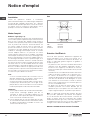
Mode d’emploi
Brûleurs à gaz (Fig. 1-3).
On allume le brûleur en ap-prochant une petite flamme
aux trous de sa partie supérieure en poussant et tournant
dans le sens contraire des aiguilles d’une montre la
manette corre-spondant jusqu’à faire coïncider l’aiguille
avec la position de maximum. Quand le bruleur est
en marche, règler la flamme selon la nécéssité. La
position de minimum se trouve à la fin de la rotation
contraire au sens des aiguilles d’une montre. Pour les
modèles à allumage automatique tourner la manette
comme indiquè cidessus, en poussant en meme
temps le bouton spècial. Pour les modèles à allumage
automatique/ simultané (à une main), il suffit d’agir sur le
bouton correspondant, comme il est indiqué cidessus.
La décharge électrique entre la petite bougie et le
brûleur allume le brûleur interessé. Quand le brûleur
est allumé, lâcher la manette, et regler la flamme selon
nécéssité. Dans le cas de modèles doués de sûreté
thermoélectrique, l’allumage du brûleur a lieu comme
dans les cas décrits cidessus en appuyant à fond sur la
manette placée à la position maximale pendant environ
3/5 secondes. Au moment où vous relâchez la manette,
assurezvous que le brûleur est allumé.
N.B.:
- on Vous conseille d’utiliser des casseroles avec un
diamètre proportionné aux brûleurs évitant que la
flamme au maximum déborde de leur fond
- ne laissez jamais de casseroles vides sur le feu allumé
- n’employez pas d’ustensiles pour cuisson grill sur les
plaques dessus verre. A la fin de la cuisson il faut fermer
le robinet principal du conduit et/ou de la bouteille.
Important
a) sur les plaques dotées de sécurité thermoélectrique,
ne pas activer l’allumage pendant plus de 15
secondes. Si, après 15 secondes le brûleur ne s’est
pas allumé, ouvrir la porte de la pièce et attendre au
moins une minute avant de réessayer.
b) sur les plaques qui ne sont pas dotées de sécurité,
en cas d’extinction des flammes d’un brûleur, fermer
le robinet correspondant et attendre au moins une
minute avant de réessayer.
Notice d’emploi

17
FR
Fig. 2

18
FR
ISO 7/1
ISO 228/1 (FR)
Fig. 3
Branchement électrique (Fig. 4)
Avant d’effectuer le branchement électrique, s’assurer
que:
• la tension de l’installation électrique correspond au
voltage indi-qué sur la plaque signalétique appliquée
au fond du plan;
• ’installationauneconnexiondeterreef-cacesuivant
les nor-mes et les dispositions de loi en vigueur. La
mise à terre est obligatoire aux termes de la loi.
Si l’appareil n’a pas de câble et/ou de prise
correspondante, ne utiliser que des câbles et des
prises, selon les données indiquées sur la plaque
signalétique et à la température de travail. Le câble ne
devra jamais atteindre une température supérieure de
50°C à celle de l’ambiance.
Pour le raccordement direct au réseau, il faut
prévoir un interrupteur omnipolaire d’une puissance
adaptée aux donneés figurant sur la plaque pour
déconnecterl’appareil en cas debesoin; conformément
aux règles d’installation, la distance d’ouver-ture des
contacts doit permettre une décon-nexion complète
dans les conditions de surtension de la catégorie III
(le câble jaune et vert de mis à la terre ne doit pas
être interrompu). La prise ou l’interrupteur omnipolaire
doivent être facilement accessibles aprè la mise
enplace de l’appareil.
Installation
Cet appareil n’est pas pourvu de dispositif d’évacuation
des produits de la combustion. On doit donc l’installer
dans des endroits suffisamment aerés suivant les
dispositions des lois en vigueur. La quantitè d’air
nécéssaire à la combustion ne doit pas etre inférieure
à 2.0 m
3
/h pour chaque kW de puissance installer. Voir
tableau puissances brûleurs.
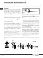
Positionnement
L’appareil est prévu pour etre encastré dans un plan de
travail comme indiqué dans la fig. 2. Avant d’installer le
plan de cuisson, placer le joint d’étanchéité
X
sur tout
le périmètre de l’ouverture.
Connexion gaz (Fig. 3)
Effectuer la connexion de l’appareil à la bouteille ou
à l’installation selon les prescriptions des normes en
vigueur s’assurant à l’avance que l’appareil est reglé
pour le type de gaz disponible. Les conditions de
préadaptation sont indiquées sur la plaque signalétique
de l’appareil. En cas contraire voir: “Adaptation à un
type de gaz différent”. Verifier aussi que la pression
d’alimentation correspond aux valeurs du tableau:
“Caractéristiques utilisateurs”.
Branchement métallique rigide/semirigide Effectuer le
branchement avec des raccords à conduits métalliques
(meme flexibles) de façon à ne pas provoquer de
contraintes aux organes internes à l’appareil.
N.B. - Quand l’installation est terminée, controler, avec
une solution savonneuse, la parfaite etoncheité de tout
le système de branchement.
Modalités d’installation
Fig. 4

19
FR
Si le câble d’alimentation est endommagé, le
constructeur, le service d’assistance technique
ou un technicien qualifié devra le remplacer afin
d’éviter toute sorte de risque.
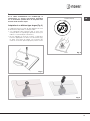
Adaptation à un différent type de gaz (Fig. 5)
Si l’appareil prevoit un type de gaz différent de celui
d’alimentation disponible, on doit proceder:
• à la substitution des injecteurs (Fig. 5) avec ceux
corréspondants au type de gaz qu’il faut utiliser (voir
tableau “Caractéristiques utilisateurs”).
• pour le réglage au minimum, tournez à l’aide d’un
tournevisappropriélavisdansl’axedurobinet(Fig.
6) après avoir placé le robinet sur la position du
minimum. Pour GPL (butane/propane) serrez à fond.
Fig. 6
seulement wok C3
Fig. 5
Fig. 6

20
FR
Dans un souci constant d’amélioration qualitative, le constructeur se réserve la possibilité d’apporter à ses produits les
modifications utiles, sans compromettre ses caractéristiques essentielles. Le constructeur décline toutes responsabilité
pour d’eventuelles inexactitudes contenues dans cette notice, imputables à des erreurs d’impression ou de transcription.
Assistance
Avant de contacter le Service Après-vente:
1. Vérifiez s’il n’est pas possible d’éliminer les pannes
sans aide.
2. Remettez l’appareil en marche pour vous assures que
l’inconvénient a été éliminé. Si tel n’est pas le cas,
débranchez à nouveau l’appareil et réessayezune
heure après.
3.
Si le problème persiste, contactez le Service Après-vente.
Communiquez:
• letypedepanne,
• lemodèle,
• le numéro de Service (numéroqui setrouve après
le mot SERVICE, sur la plaque signalétique placée à
l’arrière de l’appareil)
• votreadressecomplète,
• votrenumérodetéléphoneavecl’indicatif
Ne faites jamais appel à des techniciens non agréés
et refusez toujours des pièces détachées non
originales
CARACTERISTIQUES UTILISATEURS
BRULEURS A GAZ
ALIMENTATION BRULEUR
Ø INJECTEURS
DEBIT THERMIQUE
TYPE
PRESSION mbar
NOMINAL
CONSOMMATION
NORM. 1/100 mm W
Gaz naturel G20 20
rapide 129 3000 286
l/h
auxiliaire 77 1000 95
wok 3 141 3500 333
Gaz liquéfié
G30/G31 28-30/37
rapide 87 3000 218
g/h
auxiliaire 50 1000 73
wok 3 94 3500 254
Sayfa yükleniyor...
Sayfa yükleniyor...
Sayfa yükleniyor...
Sayfa yükleniyor...
Sayfa yükleniyor...
Sayfa yükleniyor...
Sayfa yükleniyor...
Sayfa yükleniyor...
Sayfa yükleniyor...
Sayfa yükleniyor...
Sayfa yükleniyor...
Sayfa yükleniyor...
Sayfa yükleniyor...
Sayfa yükleniyor...
Sayfa yükleniyor...
Sayfa yükleniyor...
Sayfa yükleniyor...
Sayfa yükleniyor...
Sayfa yükleniyor...
Sayfa yükleniyor...
Sayfa yükleniyor...
Sayfa yükleniyor...
Sayfa yükleniyor...
Sayfa yükleniyor...
Sayfa yükleniyor...
Sayfa yükleniyor...
Sayfa yükleniyor...
Sayfa yükleniyor...
Sayfa yükleniyor...
Sayfa yükleniyor...
Sayfa yükleniyor...
Sayfa yükleniyor...
Sayfa yükleniyor...
Sayfa yükleniyor...
Sayfa yükleniyor...
Sayfa yükleniyor...
Sayfa yükleniyor...
Sayfa yükleniyor...
Sayfa yükleniyor...
Sayfa yükleniyor...
Sayfa yükleniyor...
Sayfa yükleniyor...
Sayfa yükleniyor...
Sayfa yükleniyor...
Sayfa yükleniyor...
Sayfa yükleniyor...
Sayfa yükleniyor...
Sayfa yükleniyor...
-
 1
1
-
 2
2
-
 3
3
-
 4
4
-
 5
5
-
 6
6
-
 7
7
-
 8
8
-
 9
9
-
 10
10
-
 11
11
-
 12
12
-
 13
13
-
 14
14
-
 15
15
-
 16
16
-
 17
17
-
 18
18
-
 19
19
-
 20
20
-
 21
21
-
 22
22
-
 23
23
-
 24
24
-
 25
25
-
 26
26
-
 27
27
-
 28
28
-
 29
29
-
 30
30
-
 31
31
-
 32
32
-
 33
33
-
 34
34
-
 35
35
-
 36
36
-
 37
37
-
 38
38
-
 39
39
-
 40
40
-
 41
41
-
 42
42
-
 43
43
-
 44
44
-
 45
45
-
 46
46
-
 47
47
-
 48
48
-
 49
49
-
 50
50
-
 51
51
-
 52
52
-
 53
53
-
 54
54
-
 55
55
-
 56
56
-
 57
57
-
 58
58
-
 59
59
-
 60
60
-
 61
61
-
 62
62
-
 63
63
-
 64
64
-
 65
65
-
 66
66
-
 67
67
-
 68
68


diğer dillerde
- español: Indesit DP 1TC El manual del propietario
- français: Indesit DP 1TC Le manuel du propriétaire
- italiano: Indesit DP 1TC Manuale del proprietario
- Deutsch: Indesit DP 1TC Bedienungsanleitung
- português: Indesit DP 1TC Manual do proprietário
- English: Indesit DP 1TC Owner's manual
- русский: Indesit DP 1TC Инструкция по применению