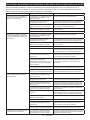
Makita KP001G Kullanım kılavuzu
- Kategori
- Güç planlayıcılar
- Tip
- Kullanım kılavuzu

KP001G
EN Cordless Planer INSTRUCTION MANUAL 11
FR Rabot sans Fil MANUEL D'INSTRUCTIONS 24
DE Akku-Hobel BEDIENUNGSANLEITUNG 38
IT Piallatrice a batteria ISTRUZIONI PER L’USO 53
NL Accuschaaf GEBRUIKSAANWIJZING 68
ES Cepillo Inalámbrico MANUAL DE
INSTRUCCIONES 83
PT Plaina a Bateria MANUAL DE INSTRUÇÕES 98
DA Batteridrevet høvl BRUGSANVISNING 112
EL 125
TR Akülü Planya KULLANMA KILAVUZU 141

2
1
2
3
1
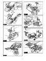
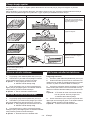
Fig.1
1
2
Fig.2
1
2
3
Fig.3
12
Fig.4
1 2 3 4
Fig.5
1
Fig.6
1
2
3
4
Fig.7
1
2
3
Fig.8

3
1
2
3
4
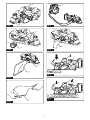
Fig.9
1
3
2
4
5
6
Fig.10
1
2
3
4
5
6
7
Fig.11
2
1
Fig.12
1
2
4
3
Fig.13
1
3
2
4
6
5
Fig.14

4
1
2
3
4
Fig.15
1
2
3
Fig.16
2
3
4
1
5
6
7
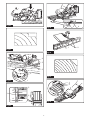
Fig.17
1
3
2
4
5
6
Fig.18
1
2
3
4
5
6
7
Fig.19

5
1
3
2
4
6
5
Fig.20
1
2
3
4
Fig.21
1
2
Fig.22
1
2
3
4
5
Fig.23
1
2
Fig.24
7
6
3
2
1
8
4
5
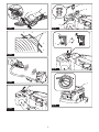
Fig.25
1
2
Fig.26

6
1
2
Fig.27
1
2
3
Fig.28
1
2
Fig.29
1
Fig.30
1
Fig.31
1
Fig.32
Fig.33
Fig.34

7
Fig.35
Fig.36
4
3
1
2
2
Fig.37
A
B
1
2
3
Fig.38
1
2
34
Fig.39
2
1
Fig.40
Fig.41
3
2
1
Fig.42

8
1
2
3
Fig.43
1
2
2
3
3
Fig.44
Fig.45
1
Fig.46
1
3
2
4
Fig.47
1
3
2
Fig.48
1
Fig.49

9
12
1
2
Fig.50
Fig.51
1
Fig.52
1
2
Fig.53
1
Fig.54
1
Fig.55

10
12
1
2
Fig.56
1
2
Fig.57
4
1
2
3
5
6
Fig.58
Fig.59

11 ENGLISH
ENGLISH (Original instructions)
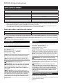
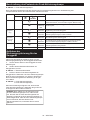
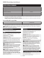
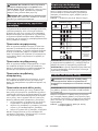
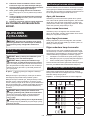
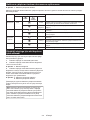
SPECIFICATIONS
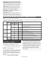
Model: KP001G
Planing width 82 mm
Planing depth 4 mm
Shiplapping depth 25 mm
No load speed 15,000 min-1
Overall length (with BL4040) 385 mm
Rated voltage D.C. 36 V - 40 V max
Net weight 3.7 - 4.9 kg
•
-
Applicable battery cartridge and charger
Charger
•
WARNING: Only use the battery cartridges and chargers listed above.
Intended use
The tool is intended for planing wood.
Noise
-
Sound pressure level (L
Sound power level (L
NOTE:
measured in accordance with a standard test method
NOTE:
WARNING: Wear ear protection.
WARNING: The noise emission during actual
value(s) depending on the ways in which the
tool is used especially what kind of workpiece is
processed.
WARNING: Be sure to identify safety mea-
sures to protect the operator that are based on an
estimation of exposure in the actual conditions of
use (taking account of all parts of the operating
cycle such as the times when the tool is switched
trigger time).
Vibration
-
Work mode: planing softwood
h2
2
NOTE:
measured in accordance with a standard test method
NOTE:
WARNING: The vibration emission during
declared value(s) depending on the ways in which
the tool is used especially what kind of workpiece
is processed.
WARNING: Be sure to identify safety mea-
sures to protect the operator that are based on an
estimation of exposure in the actual conditions of
use (taking account of all parts of the operating
cycle such as the times when the tool is switched
trigger time).
EC Declaration of Conformity
For European countries only
to this instruction manual.

12 ENGLISH
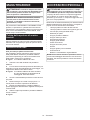
SAFETY WARNINGS
General power tool safety warnings
WARNING: Read all safety warnings, instruc-
with this power tool.
Save all warnings and instruc-
tions for future reference.
(cordless) power tool.
Cordless Planer Safety Warnings
1. Wait for the cutter to stop before setting the
tool down.
2. Use clamps or another practical way to secure
and support the workpiece to a stable plat-
form.
to loss of control.
3. Rags, cloth, cord, string and the like should
never be left around the work area.
4. Avoid cutting nails. Inspect for and remove all
nails from the workpiece before operation.
5.
Use only sharp blades. Handle the blades very carefully.
6. Be sure the blade installation bolts are
securely tightened before operation.
7.
8. Keep hands away from rotating parts.
9. Before using the tool on an actual workpiece,
let it run for a while. Watch for vibration or
wobbling that could indicate poor installation
or a poorly balanced blade.
10. Make sure the blade is not contacting the
workpiece before the switch is turned on.
11.
Wait until the blade attains full speed before cutting.
12.
come to a complete stop before adjusting
depth of cut.
13.
Chute may jam when cutting damp wood.
Clean out chips with a stick.
14. Do not leave the tool running. Operate the tool
only when hand-held.
15.
When replace the blades or some parts on the
drum, make sure to replace the parts on both
sides of the drum as a set. Otherwise, the resulting
16.
17.
Always use the correct dust mask/respirator for
the material and application you are working with.
18. Operate the tool on stable condition. Operation
SAVE THESE INSTRUCTIONS.
WARNING: DO NOT let comfort or familiarity
with product (gained from repeated use) replace
strict adherence to safety rules for the subject
product.
MISUSE or failure to follow the safety rules stated
in this instruction manual may cause serious
personal injury.
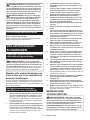
Important safety instructions for
battery cartridge
1.
Before using battery cartridge, read all instruc-
tions and cautionary markings on (1) battery
charger, (2) battery, and (3) product using battery.
2. Do not disassemble or tamper with the battery
cartridge.
or explosion.
3. If operating time has become excessively
shorter, stop operating immediately. It may
result in a risk of overheating, possible burns
and even an explosion.
4. If electrolyte gets into your eyes, rinse them
out with clear water and seek medical atten-
tion right away. It may result in loss of your
eyesight.
5. Do not short the battery cartridge:
(1) Do not touch the terminals with any con-
ductive material.
(2) Avoid storing battery cartridge in a con-
tainer with other metal objects such as
nails, coins, etc.
(3) Do not expose battery cartridge to water
or rain.
A battery short can cause a large current
breakdown.
6. Do not store and use the tool and battery car-
tridge in locations where the temperature may
reach or exceed 50 °C (122 °F).
7. Do not incinerate the battery cartridge even if
it is severely damaged or is completely worn
8. Do not nail, cut, crush, throw, drop the battery
cartridge, or hit against a hard object to the
battery cartridge.
9. Do not use a damaged battery.
10.
The contained lithium-ion batteries are subject to
the Dangerous Goods Legislation requirements.
forwarding agents, special requirement on pack-
-
ing an expert for hazardous material is required.
national regulations.
around in the packaging.
11. When disposing the battery cartridge, remove
it from the tool and dispose of it in a safe
place. Follow your local regulations relating to
disposal of battery.

13 ENGLISH
12. Use the batteries only with the products
-
13. If the tool is not used for a long period of time,
the battery must be removed from the tool.
14. During and after use, the battery cartridge may
take on heat which can cause burns or low
temperature burns. Pay attention to the han-
dling of hot battery cartridges.
15. Do not touch the terminal of the tool imme-
diately after use as it may get hot enough to
cause burns.
16. Do not allow chips, dust, or soil stuck into the
terminals, holes, and grooves of the battery
cartridge.
-
17. Unless the tool supports the use near
high-voltage electrical power lines, do not use
the battery cartridge near a high-voltage elec-
trical power lines.
18. Keep the battery away from children.
SAVE THESE INSTRUCTIONS.
CAUTION: Only use genuine Makita batteries.
charger.
Tips for maintaining maximum
battery life
1. Charge the battery cartridge before completely
discharged. Always stop tool operation and
charge the battery cartridge when you notice
less tool power.
2. Never recharge a fully charged battery car-
tridge. Overcharging shortens the battery
service life.
3.
Charge the battery cartridge with room tempera-
ture at 10 °C - 40 °C (50 °F - 104 °F). Let a hot
battery cartridge cool down before charging it.
4. When not using the battery cartridge, remove
it from the tool or the charger.
5. Charge the battery cartridge if you do not use
it for a long period (more than six months).
Important safety instructions for
wireless unit
1. Do not disassemble or tamper with the wire-
less unit.
2. Keep the wireless unit away from young chil-
dren. If accidentally swallowed, seek medical
attention immediately.
3. Use the wireless unit only with Makita tools.
4. Do not expose the wireless unit to rain or wet
conditions.
5. Do not use the wireless unit in places where
the temperature exceeds 50 °C (122 °F).
6. Do not operate the wireless unit in places
where medical instruments, such as heart
pace makers are nearby.
7. Do not operate the wireless unit in places
where automated devices are nearby. If oper-
or error.
8. Do not operate the wireless unit in places
under high temperature or places where
static electricity or electrical noise could be
generated.
9.
The wireless unit can produce electromagnetic
10. The wireless unit is an accurate instrument. Be
careful not to drop or strike the wireless unit.
11. Avoid touching the terminal of the wireless
unit with bare hands or metallic materials.
12. Always remove the battery on the product
when installing the wireless unit into it.
13. When opening the lid of the slot, avoid the
place where dust and water may come into the
slot. Always keep the inlet of the slot clean.
14. Always insert the wireless unit in the correct
direction.
15. Do not press the wireless activation button
on the wireless unit too hard and/or press the
button with an object with a sharp edge.
16. Always close the lid of the slot when
operating.
17. Do not remove the wireless unit from the slot
while the power is being supplied to the tool.
unit.
18. Do not remove the sticker on the wireless unit.
19. Do not put any sticker on the wireless unit.
20. Do not leave the wireless unit in a place where
static electricity or electrical noise could be
generated.
21. Do not leave the wireless unit in a place sub-
ject to high heat, such as a car sitting in the
sun.
22. Do not leave the wireless unit in a dusty or
powdery place or in a place corrosive gas
could be generated.
23. Sudden change of the temperature may bedew
the wireless unit. Do not use the wireless unit
until the dew is completely dried.
24. When cleaning the wireless unit, gently wipe
with a dry soft cloth. Do not use benzine, thin-
ner, conductive grease or the like.
25. When storing the wireless unit, keep it in the
supplied case or a static-free container.
26. Do not insert any devices other than Makita
wireless unit into the slot on the tool.
27. Do not use the tool with the lid of the slot dam-
aged.
cause malfunction.
28. Do not pull and/or twist the lid of the slot more
than necessary.
from the tool.
29. Replace the lid of the slot if it is lost or
damaged.
SAVE THESE INSTRUCTIONS.

14 ENGLISH
FUNCTIONAL
DESCRIPTION
CAUTION: Always be sure that the tool is
before adjusting or checking function on the tool.
Installing or removing battery
cartridge
CAUTION:
installing or removing of the battery cartridge.
CAUTION: Hold the tool and the battery car-
cartridge.
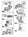
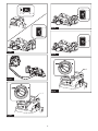
Fig.1: 1. Red indicator 2. Button 3.
CAUTION: Always install the battery cartridge
fully until the red indicator cannot be seen. If not,
CAUTION: Do not install the battery cartridge
forcibly.
Tool / battery protection system
-
-
placed under one of the following conditions:
Overload protection
overloaded. Then turn the tool on to restart.
Overheat protection
Overdischarge protection
Protections against other causes
that could damage the tool and allows the tool to stop
halt or stop in operation.
restart.
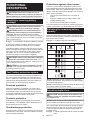
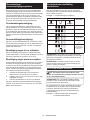
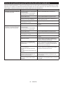
Indicating the remaining battery
capacity
-
light up for a few seconds.
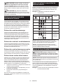
Fig.2: 1. Indicator lamps 2.
Indicator lamps Remaining
capacity
Lighted Blinking
75% to 100%
50% to 75%
25% to 50%
0% to 25%
Charge the
malfunctioned.
NOTE: Depending on the conditions of use and the
NOTE:
Adjusting depth of cut
CAUTION:
blades to come to a complete stop before adjust-
ing depth of cut.
NOTE:
the depth scale.
Fig.3: 1. 2. Pointer 3. Depth
scale

15 ENGLISH
Switch action
WARNING: Before installing the battery car-
tridge into the tool, always check to see that the
switch trigger actuates properly and returns to
the "OFF" position when released.
WARNING:
by taping down or some other means.
WARNING: NEVER use the tool if it runs when
you simply pull the switch trigger without press-
NOTICE: Do not pull the switch trigger hard
This can
switch trigger. Release the switch trigger to stop.
Fig.4: 1. Switch trigger 2.
Foot
Fig.5: 1. 2. 3. 4. Work
surface
Accidental restart preventive
function
switch trigger, the tool does not start. To start the tool,
release the switch trigger, and then pull the switch trig-
Electronic function
The tool is equipped with the following electronic func-
Electric brake
Makita Service Center.
Soft start feature
The soft-start function minimizes start-up shock, and
ASSEMBLY
CAUTION: Always be sure that the tool is
before carrying out any work on the tool.
Box wrench storage
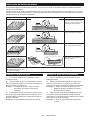
Fig.6: 1. Box wrench
Removing and installing planer
blades
CAUTION: Tighten the blade installation bolts
carefully when attaching the planer blades to
the tool. Always check to see they are tightened
securely.
CAUTION: Handle the planer blades very
-
gers or hands when removing and installing the
planer blades.
CAUTION: Use only the Makita wrench pro-
vided to remove and install the planer blades.
-
NOTICE: To install planer blades, clean out all
chips or foreign matter adhering to the drum or
the planer blades. Use planer blades of the same
dimensions and weight, otherwise drum oscilla-
tion/vibration, causing poor planing action, and
tool breakdown will result.
For tool with conventional planer
blades
NOTE:
the drum. Repeat the following procedures for each
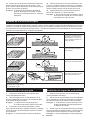
Removing conventional planer blades
1.
2.
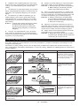
Fig.7: 1. 2. Drum plate
3.
plate) 4. Drum
3. Untighten the screws from the conventional planer
Fig.8: 1. Screws 2.
3.

16 ENGLISH
Installing conventional planer blades
1.
gauge, aligning its cutting edge along the guide wall on
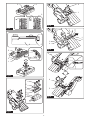
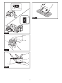
Fig.9: 1. 2. Blade gauge
3. Cutting edge 4. Guide wall
2.
3. -
4.
screws to secure it in place.
Fig.10: 1. 2. Conventional planer
3. Screw 4. Positioning guide 5. Rear
side wall 6. Blade gauge
5. Clean out all the wood chips and foreign matters
6.
into the guide groove in the drum, and then place the
7.
Fig.11: 1. Positioning guide 2.
3. Guide groove 4. Drum 5. Drum plate
6. 7. Installation
For tool with mini planer blades
NOTE:
the drum. Repeat the following procedures for each
Removing mini planer blades
1.
Fig.12: 1. 2. Box wrench
2.
cover side.
Fig.13: 1. 2. Drum 3. Belt cover 4.
NOTE:
maintenance.
Installing mini planer blades
1. Clean out all the wood chips and foreign matters
2.
3.
Fig.14: 1. 2. Drum 3. Set plate
4. Belt cover 5. 6. Box
wrench
Mini planer blade calibration
-
1.
2.
cover side.
3.
4.
Fig.15: 1. 2. Drum plate 3. Set plate
4. Drum
5. Loosen the screws on the set plate one turn to
Fig.16: 1. Screws 2. Set plate 3.
6. Clean out all the wood chips and foreign matters
7.
aligning its cutting edge along the guide wall on the
8.
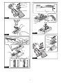
Fig.17: 1. 2. Blade gauge
3. Cutting edge 4. Guide wall 5. Set plate
6. Guide ridge
7. Guide groove
9. -
10.
screws to secure it in place.
Fig.18: 1. 2. Set plate 3. Screw
4. Positioning guide 5. Rear side wall
6. Blade gauge
11.
into the guide groove in the drum, and then place the
Fig.19: 1. Positioning guide 2.
3. Guide groove 4. Drum 5. Drum plate
6. Set plate 7.
12.
13.
Fig.20: 1. 2. Drum 3. Set plate
4. Belt cover 5. 6. Box
wrench

17 ENGLISH
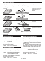
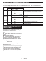
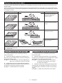
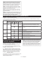
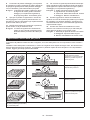
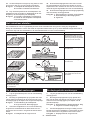
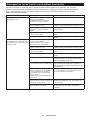
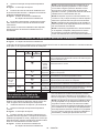
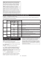
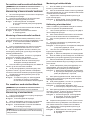
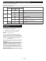
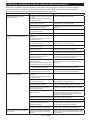
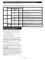
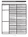
Planer blade settings
Planing surface Blade setting Cause
Correct setting
(A) (B)
(C)
Cutting edges sit on a level with
to side parallel to the sole of
the plane.
Gouging at start
(A) (B)
(C)
Cutting edges underreach the
Gouging at end
(B)
(A) (C)
Cutting edges overpass the
(B)
(B)
(A)
(C)
Cutting edges sit side to side
unparalleled to the sole of the
plane.
Installing guide rule
1.
2.
Fig.21: 1. Belt cover 2. Guide rule 3.
4. Mounting hole
3.
secure it in the required position.
Fig.22: 1. 2.
Installing depth guide
1.
2.
side of the tool head.
Fig.23: 1. Belt cover 2. Depth guide 3. Washer
4. 5. Mounting hole
3.
secure it in the required position.
Fig.24: 1. Depth guide 2.
Installing chamfering rules
Optional accessory
1.
upwards.
2.
in the edge fences, and secure them with the washers
3. Mount the chamfering rules (sets of edge fences
the tool head.
Fig.25: 1. 2. 3. Mounting
arm 4. 5. Guide slit 6. Washer
7. 8. Mounting hole
4.
secure them in the required position.
Fig.26: 1. 2.

18 ENGLISH
Dust and wood chip extraction
right side of discharge openings. Cover one of the dis-
dust extraction direction with the stopper.
To detach the stopper from the discharge opening, turn
lock, and then pull it apart.
Fig.27: 1. Stopper 2. Handle
of the openings aligning the locking slot in the stopper
place.
Fig.28: 1. Stopper 2. Locking slot 3. Guide
Dust bag
Optional accessory
Fig.29: 1. 2. Discharge opening
adhering inside, which might hamper further collection.
Fig.30: 1.
NOTE:
performed.
Connecting a vacuum cleaner
a hose of the vacuum cleaner to one of the discharge
Fig.31: 1. Vacuum cleaner
Elbow
Optional accessory
-
-
Fig.32: 1.
OPERATION
CAUTION:
the switch handle and the other hand on the depth
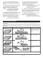
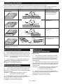
Planing operation
1.
2.
3. Turn the tool on and wait until it attains full speed.
4.
level and even with the workpiece surface.
Fig.33
5. -
piece surface in the middle of operation, and push the
Fig.34
NOTE:
6.
Fig.35
NOTE:-
pressure to hold the tool during operation.
NOTE:
deep enough on workpiece.
shallow cutting depth and make more passes.
Shiplapping (Rabbeting)
Fig.36
1. Install the guide rule and depth guide in the tool
2.
3. Draw a cutting line on the workpiece and align the
Fig.37: 1. Blade edge 2. Cutting line 3. Depth guide
4.
NOTE:
Fig.38: 1. Blade edge 2. Side end of drum 3. Side
4. Slide the edge fence in the guide rule inwards until
it comes in contact with the side wall of the workpiece.
Fig.39: 1. Guide rule 2. 3. Side wall
4.

19 ENGLISH
5.
with the whole edge fence sliding along the side wall of
the workpiece.
NOTE:
attachment holes in the guide fence.
Fig.40: 1. 2.
Chamfering
Fig.41
corner edge of the workpiece.
Fig.42: 1. V groove for medium chamfers 2. V
groove for small chamfers 3. V groove for
large chamfers
Using chamfering rules
Optional accessory
1. Slide the edge fences in the chamfering rules
of the workpiece.
2.
screws.
3.
with the whole edge fences sliding along the corner
walls of the workpiece.
Fig.43: 1. Chamfering rule 2.
3.
NOTE:
planning, starting from small chamfering to larger
Fig.44: 1. 2. Small chamfering
3. Large chamfering
WIRELESS ACTIVATION
FUNCTION
What you can do with the wireless
activation function
-
Fig.45
To use the wireless activation function, prepare follow-
ing items:
activation function
The overview of the wireless activation function
setting is as follows. Refer to each section for detail
procedures.
1. Installing the wireless unit
2. Tool registration for the vacuum cleaner
3. Starting the wireless activation function
Installing the wireless unit
Optional accessory
CAUTION:
surface when installing the wireless unit.
NOTICE: Clean the dust and dirt on the tool
before installing the wireless unit. Dust or dirt
wireless unit.
NOTICE: To prevent the malfunction caused by
static, touch a static discharging material, such
as a metal part of the tool, before picking up the
wireless unit.
NOTICE: When installing the wireless unit,
always be sure that the wireless unit is inserted
in the correct direction and the lid is completely
closed.
1.
Fig.46: 1. Lid
2. Insert the wireless unit to the slot and then close
the lid.
with the recessed portions on the slot.
Fig.47: 1. Wireless unit 2. 3. Lid
4. Recessed portion
Fig.48: 1. Wireless unit 2. Hook 3. Lid
case or a static-free container.
NOTICE: Always use the hooks on the back of
the lid when removing the wireless unit. If the
hooks do not catch the wireless unit, close the lid
Tool registration for the vacuum
cleaner
NOTE:
wireless activation function is required for the tool
registration.
NOTE:
NOTE: During the tool registration, do not pull the
switch trigger or turn on the power switch on the
vacuum cleaner.
NOTE: Refer to the instruction manual of the vacuum
cleaner, too.

20 ENGLISH
-
1.
tool.
2.
Fig.49: 1.
3. -
uum cleaner for 3 seconds until the wireless activation
-
Fig.50: 1. 2. Wireless
activation lamp
If the vacuum cleaner and the tool are linked success-
NOTE:
in green after 20 seconds elapsed. Press the wireless
-
-
NOTE: When performing two or more tool registra-
-
Starting the wireless activation
function
NOTE:
cleaner prior to the wireless activation.
NOTE: Refer to the instruction manual of the vacuum
cleaner, too.
switch operation of the tool.
1. Install the wireless unit to the tool.
2. Connect the hose of the vacuum cleaner with the
tool.
Fig.51
3.
Fig.52: 1.
4.
Fig.53: 1. 2. Wireless
activation lamp
5. Turn on the tool. Check if the vacuum cleaner runs
while the tool is operating.
To stop the wireless activation of the vacuum cleaner,
NOTE: The wireless activation lamp on the tool will
NOTE:
There is a time lag when the vacuum cleaner detects
a switch operation of the tool.
NOTE: The transmission distance of the wireless unit
circumstances.
NOTE: When two or more tools are registered to
another user is using the wireless activation function.
Sayfa yükleniyor ...
Sayfa yükleniyor ...
Sayfa yükleniyor ...
Sayfa yükleniyor ...
Sayfa yükleniyor ...
Sayfa yükleniyor ...
Sayfa yükleniyor ...
Sayfa yükleniyor ...
Sayfa yükleniyor ...
Sayfa yükleniyor ...
Sayfa yükleniyor ...
Sayfa yükleniyor ...
Sayfa yükleniyor ...
Sayfa yükleniyor ...
Sayfa yükleniyor ...
Sayfa yükleniyor ...
Sayfa yükleniyor ...
Sayfa yükleniyor ...
Sayfa yükleniyor ...
Sayfa yükleniyor ...
Sayfa yükleniyor ...
Sayfa yükleniyor ...
Sayfa yükleniyor ...
Sayfa yükleniyor ...
Sayfa yükleniyor ...
Sayfa yükleniyor ...
Sayfa yükleniyor ...
Sayfa yükleniyor ...
Sayfa yükleniyor ...
Sayfa yükleniyor ...
Sayfa yükleniyor ...
Sayfa yükleniyor ...
Sayfa yükleniyor ...
Sayfa yükleniyor ...
Sayfa yükleniyor ...
Sayfa yükleniyor ...
Sayfa yükleniyor ...
Sayfa yükleniyor ...
Sayfa yükleniyor ...
Sayfa yükleniyor ...
Sayfa yükleniyor ...
Sayfa yükleniyor ...
Sayfa yükleniyor ...
Sayfa yükleniyor ...
Sayfa yükleniyor ...
Sayfa yükleniyor ...
Sayfa yükleniyor ...
Sayfa yükleniyor ...
Sayfa yükleniyor ...
Sayfa yükleniyor ...
Sayfa yükleniyor ...
Sayfa yükleniyor ...
Sayfa yükleniyor ...
Sayfa yükleniyor ...
Sayfa yükleniyor ...
Sayfa yükleniyor ...
Sayfa yükleniyor ...
Sayfa yükleniyor ...
Sayfa yükleniyor ...
Sayfa yükleniyor ...
Sayfa yükleniyor ...
Sayfa yükleniyor ...
Sayfa yükleniyor ...
Sayfa yükleniyor ...
Sayfa yükleniyor ...
Sayfa yükleniyor ...
Sayfa yükleniyor ...
Sayfa yükleniyor ...
Sayfa yükleniyor ...
Sayfa yükleniyor ...
Sayfa yükleniyor ...
Sayfa yükleniyor ...
Sayfa yükleniyor ...
Sayfa yükleniyor ...
Sayfa yükleniyor ...
Sayfa yükleniyor ...
Sayfa yükleniyor ...
Sayfa yükleniyor ...
Sayfa yükleniyor ...
Sayfa yükleniyor ...
Sayfa yükleniyor ...
Sayfa yükleniyor ...
Sayfa yükleniyor ...
Sayfa yükleniyor ...
Sayfa yükleniyor ...
Sayfa yükleniyor ...
Sayfa yükleniyor ...
Sayfa yükleniyor ...
Sayfa yükleniyor ...
Sayfa yükleniyor ...
Sayfa yükleniyor ...
Sayfa yükleniyor ...
Sayfa yükleniyor ...
Sayfa yükleniyor ...
Sayfa yükleniyor ...
Sayfa yükleniyor ...
Sayfa yükleniyor ...
Sayfa yükleniyor ...
Sayfa yükleniyor ...
Sayfa yükleniyor ...
Sayfa yükleniyor ...
Sayfa yükleniyor ...
Sayfa yükleniyor ...
Sayfa yükleniyor ...
Sayfa yükleniyor ...
Sayfa yükleniyor ...
Sayfa yükleniyor ...
Sayfa yükleniyor ...
Sayfa yükleniyor ...
Sayfa yükleniyor ...
Sayfa yükleniyor ...
Sayfa yükleniyor ...
Sayfa yükleniyor ...
Sayfa yükleniyor ...
Sayfa yükleniyor ...
Sayfa yükleniyor ...
Sayfa yükleniyor ...
Sayfa yükleniyor ...
Sayfa yükleniyor ...
Sayfa yükleniyor ...
Sayfa yükleniyor ...
Sayfa yükleniyor ...
Sayfa yükleniyor ...
Sayfa yükleniyor ...
Sayfa yükleniyor ...
Sayfa yükleniyor ...
Sayfa yükleniyor ...
Sayfa yükleniyor ...
Sayfa yükleniyor ...
Sayfa yükleniyor ...
Sayfa yükleniyor ...
Sayfa yükleniyor ...
Sayfa yükleniyor ...
Sayfa yükleniyor ...
Sayfa yükleniyor ...
Sayfa yükleniyor ...
Sayfa yükleniyor ...
Sayfa yükleniyor ...
-
 1
1
-
 2
2
-
 3
3
-
 4
4
-
 5
5
-
 6
6
-
 7
7
-
 8
8
-
 9
9
-
 10
10
-
 11
11
-
 12
12
-
 13
13
-
 14
14
-
 15
15
-
 16
16
-
 17
17
-
 18
18
-
 19
19
-
 20
20
-
 21
21
-
 22
22
-
 23
23
-
 24
24
-
 25
25
-
 26
26
-
 27
27
-
 28
28
-
 29
29
-
 30
30
-
 31
31
-
 32
32
-
 33
33
-
 34
34
-
 35
35
-
 36
36
-
 37
37
-
 38
38
-
 39
39
-
 40
40
-
 41
41
-
 42
42
-
 43
43
-
 44
44
-
 45
45
-
 46
46
-
 47
47
-
 48
48
-
 49
49
-
 50
50
-
 51
51
-
 52
52
-
 53
53
-
 54
54
-
 55
55
-
 56
56
-
 57
57
-
 58
58
-
 59
59
-
 60
60
-
 61
61
-
 62
62
-
 63
63
-
 64
64
-
 65
65
-
 66
66
-
 67
67
-
 68
68
-
 69
69
-
 70
70
-
 71
71
-
 72
72
-
 73
73
-
 74
74
-
 75
75
-
 76
76
-
 77
77
-
 78
78
-
 79
79
-
 80
80
-
 81
81
-
 82
82
-
 83
83
-
 84
84
-
 85
85
-
 86
86
-
 87
87
-
 88
88
-
 89
89
-
 90
90
-
 91
91
-
 92
92
-
 93
93
-
 94
94
-
 95
95
-
 96
96
-
 97
97
-
 98
98
-
 99
99
-
 100
100
-
 101
101
-
 102
102
-
 103
103
-
 104
104
-
 105
105
-
 106
106
-
 107
107
-
 108
108
-
 109
109
-
 110
110
-
 111
111
-
 112
112
-
 113
113
-
 114
114
-
 115
115
-
 116
116
-
 117
117
-
 118
118
-
 119
119
-
 120
120
-
 121
121
-
 122
122
-
 123
123
-
 124
124
-
 125
125
-
 126
126
-
 127
127
-
 128
128
-
 129
129
-
 130
130
-
 131
131
-
 132
132
-
 133
133
-
 134
134
-
 135
135
-
 136
136
-
 137
137
-
 138
138
-
 139
139
-
 140
140
-
 141
141
-
 142
142
-
 143
143
-
 144
144
-
 145
145
-
 146
146
-
 147
147
-
 148
148
-
 149
149
-
 150
150
-
 151
151
-
 152
152
-
 153
153
-
 154
154
-
 155
155
-
 156
156
-
 157
157
-
 158
158


Makita KP001G Kullanım kılavuzu
- Kategori
- Güç planlayıcılar
- Tip
- Kullanım kılavuzu
Diğer dillerde
- español: Makita KP001G Manual de usuario
- français: Makita KP001G Manuel utilisateur
- italiano: Makita KP001G Manuale utente
- Deutsch: Makita KP001G Benutzerhandbuch
- português: Makita KP001G Manual do usuário
- dansk: Makita KP001G Brugermanual
- Nederlands: Makita KP001G Handleiding
İlgili Makaleler
Diğer Belgeler
-
Maktec MT111 Kullanım kılavuzu
-
Hikoki P20SA2 Kullanım kılavuzu
-
DeWalt DCP580 Kullanım kılavuzu
-
-
Hitachi P18DSL Handling Instructions Manual
-
Stanley STPP7502 Kullanım kılavuzu
-
Bosch PHO 1 Şartname
-
Meister BEH 600 C Translation Of The Original Instructions
-
Bosch GHO 18 V Kullanma talimatları