Grundfos Conex DIA-G Installation And Operating Instructions Manual
- Tip
- Installation And Operating Instructions Manual

Conex
®
DIA-G
Gas warning controller
Installation and operating instructions
GRUNDFOS INSTRUCTIONS

2

3
Table of contents
Conex
®
DIA-G
English (GB)
Installation and operating instructions. . . . . . . . . . . . . . . . . . . . . . . . . . . . . . . . . 4
Deutsch (DE)
Montage- und Betriebsanleitung . . . . . . . . . . . . . . . . . . . . . . . . . . . . . . . . . . . . 55
Español (ES)
Instrucciones de instalación y funcionamiento . . . . . . . . . . . . . . . . . . . . . . . . 106
Français (FR)
Notice d'installation et de fonctionnement. . . . . . . . . . . . . . . . . . . . . . . . . . . . 157
Hrvatski (HR)
Montažne i pogonske upute . . . . . . . . . . . . . . . . . . . . . . . . . . . . . . . . . . . . . . 208
Italiano (IT)
Istruzioni di installazione e funzionamento . . . . . . . . . . . . . . . . . . . . . . . . . . . 259
Lietuviškai (LT)
Įrengimo ir naudojimo instrukcija . . . . . . . . . . . . . . . . . . . . . . . . . . . . . . . . . . 310
Nederlands (NL)
Installatie- en bedieningsinstructies . . . . . . . . . . . . . . . . . . . . . . . . . . . . . . . . 361
Polski (PL)
Instrukcja montażu i eksploatacji . . . . . . . . . . . . . . . . . . . . . . . . . . . . . . . . . . 412
Português (PT)
Instruções de instalação e funcionamento . . . . . . . . . . . . . . . . . . . . . . . . . . . 463
Română (RO)
Instrucţiuni de instalare şi utilizare . . . . . . . . . . . . . . . . . . . . . . . . . . . . . . . . . 514
Русский (RU)
Паспорт, Руководство по монтажу и эксплуатации . . . . . . . . . . . . . . . . . . 565
Türkçe (TR)
Montaj ve kullanım kılavuzu . . . . . . . . . . . . . . . . . . . . . . . . . . . . . . . . . . . . . . 616
Declaration of conformity . . . . . . . . . . . . . . . . . . . . . . . . . . . . . . . . . . . . . . . . 668

English (GB)
4
English (GB) Installation and operating instructions
Original installation and operating instructions
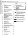
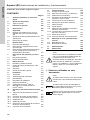
CONTENTS
Page
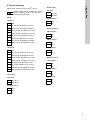
1. Symbols used in this document
1. Symbols used in this document
4
2. Device settings
5
2.1 Sensor types
7
3. General information
7
4. Applications
7
5. Safety
8
5.1 Risks when safety instructions are not
observed
8
5.2 Obligations of the owner/operations
manager
8
5.3 Avoidance of danger
8
6. Identification
9
6.1 Nameplate
9
6.2 Type key, gas warning controllers
9
6.3 Type key, gas warning systems,
prepacked (with sensors and sensor
equipment)
10
7. Product description and accessories
11
7.1 General description
11
7.2 Dimensional sketches
13
8. Technical data
14
8.1 Signal inputs and outputs
15
8.2 Setting ranges for alarms / limit values
15
8.3 Sensors
15
8.4 Measuring and setting ranges
16
9. Installation
17
9.1 Transport
17
9.2 Intermediate storage
17
9.3 Unpacking
17
9.4 Installation requirements
17
9.5 Installation notes
17
9.6 Installation of the Conex
®
DIA-G
18
9.7 Assembling the Conex
®
DIA-G sensor
interface
19
10. Commissioning/electrical connections
19
10.1 Conex
®
DIA-G terminal assignment
20
10.2 Power supply connection
21
10.3 Connecting a backup battery
22
10.4 Relay outputs
22
10.5 Current output
22
10.6 Terminal assignment for Conex
®
DIA-G
sensor interface
23
10.7 Connection of sensors
24
11. Operation
27
11.1 Initial start-up
27
11.2 Control and display elements
28
11.3 Operating modes
28
11.4 Display elements during initial
commissioning
28
11.5 Operating instructions
29
11.6 Software overview
30
11.7 Main menu
35
11.8 Setup
35
11.9 Parameterising the sensors
41
11.10 Requesting settings in the service menu
45
11.11 Fine adjustment menu
47
11.12 Actions during operation
49
12. Error messages and fault finding
52
12.1 Error messages
52
12.2 Fault finding
53
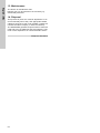
13. Maintenance
54
14. Disposal
54
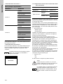
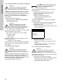
Warning
These complete installation and operating
instructions are also available on
www.Grundfos.com.
Prior to installation, read these installation
and operating instructions. Installation and
operation must comply with local
regulations and accepted codes of good
practice.
Warning
If these safety instructions are not
observed, it may result in personal injury.
Caution
If these safety instructions are not
observed, it may result in malfunction or
damage to the equipment.
Note
Notes or instructions that make the job
easier and ensure safe operation.

English (GB)
5
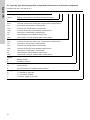
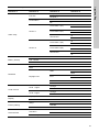
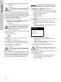
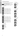
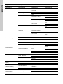
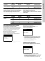
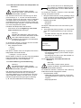
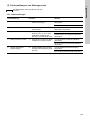
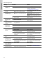
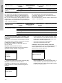
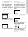
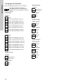
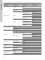
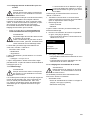
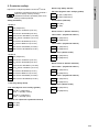
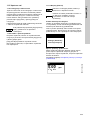
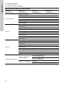
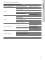
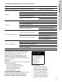
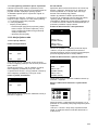
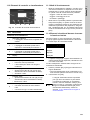
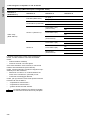
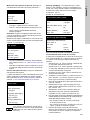
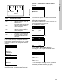
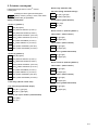
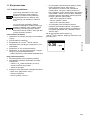
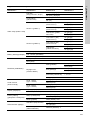
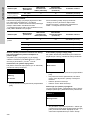
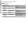
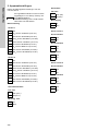
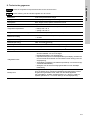
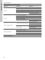
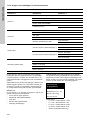
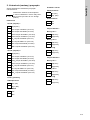
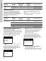
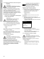
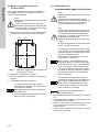
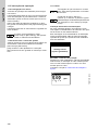
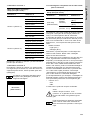
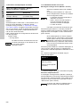
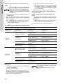
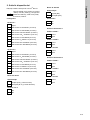
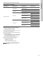
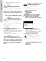
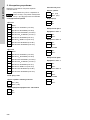
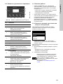
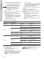
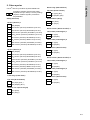
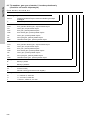
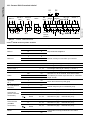
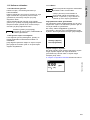
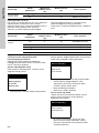
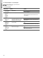
2. Device settings
Note the key settings for the Conex
®
DIA-G.
Setup
Note
The set values can be stored in the "Setup
/ Factory setting" menu so that you can
access them again later.
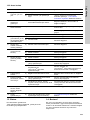
Sensor 1
Off
Cl
2
sensor 91835237 (314-011)
Cl
2
sensor 96732268 (314-021)
ClO
2
sensor 95700837 (314-041)
ClO
2
sensor 91835237 (314-011)
O
3
sensor 95700838 (314-071)
O
3
sensor 96687714 (314-013)
HCl sensor 95700840 (314-061)
NH
3
sensor 95700839 (314-031)
Sensor 2
Off
Cl
2
sensor 91835237 (314-011)
Cl
2
sensor 96732268 (314-021)
ClO
2
sensor 95700837 (314-041)
ClO
2
sensor 91835237 (314-011)
O
3
sensor 95700838 (314-071)
O
3
sensor 96687714 (314-013)
HCl sensor 95700840 (314-061)
NH
3
sensor 95700839 (314-031)
Limit relay
Fail safe
On (N.C.)
Off (N.O.)
Confirm. LV 2
Yes
No
Alarm relay
Fail safe
On (NC)
Off (NO)
Confirmation
Yes
No
Alarm sensor 1
Limit value 1
On
Off
Limit value 2
On
Off
Test sensor
On
Off
Alarm sensor 2
Limit value 1
On
Off
Limit value 2
On
Off
Test sensor
On
Off

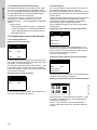
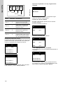
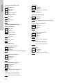
English (GB)
6
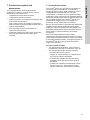
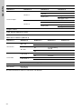
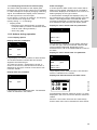
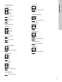
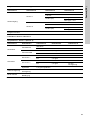
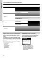
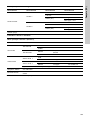
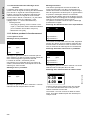
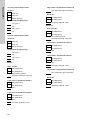
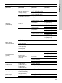
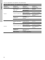
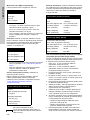
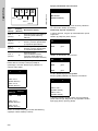
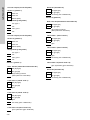
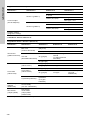
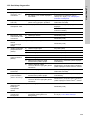
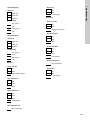
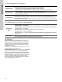
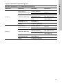
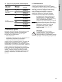
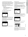
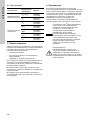
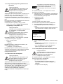
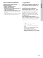
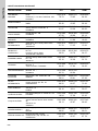
Sensor 1
Sensor 2
Current output
Sensor 1
0-20 mA
4-20 mA
Others:
Assignment
min. ppm =
mA
max. ppm =
mA
Current output
Sensor 2
0-20 mA
4-20 mA
Others:
Assignment
min. ppm =
mA
max. ppm =
mA
Auto. test S1
Off
On
days testing interval
Limit value 1
Off
On
ppm
Limit value 2
Off
On
ppm
sec delay
Limit value 1/2
ppm hysteresis
Alarm S1
Off
On
sec delay
Auto. test S2
Off
On
days testing interval
Limit value 1
Off
On
ppm
Limit value 2
Off
On
ppm
sec delay
Limit value 1/2
ppm hysteresis
Alarm S2
Off
On
sec delay

English (GB)
7
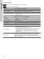
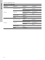
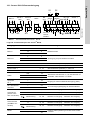
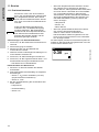
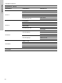
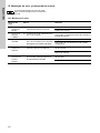
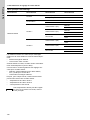
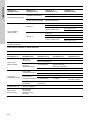
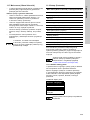
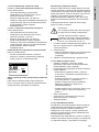
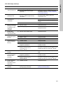
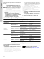
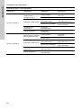
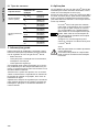
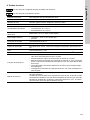
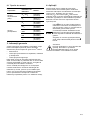
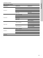
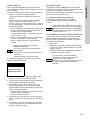
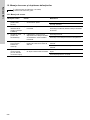
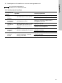
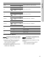
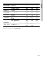
2.1 Sensor types
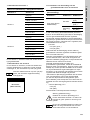
3. General information
These installation and operating instructions contain
all information important for users of the
Conex
®
DIA-G gas warning controller.
• technical data
• instructions on commissioning, use and
maintenance
• safety information.
Should you require further information or should you
encounter problems that are not handled in sufficient
depth in this manual, please contact Grundfos Water
Treatment.
We shall be pleased to support you with our
comprehensive know-how in the fields of measuring
and control technology as well as water treatment.
We always welcome suggestions on how to optimise
our installation and operating instructions to satisfy
our customers.
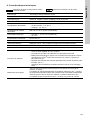
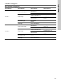
4. Applications
The Conex
®
DIA-G gas warning controllers are used
to evaluate suitable sensors for monitoring the
concentration of chlorine (Cl
2
),
chlorine dioxide (ClO
2
), ozone (O
3
), ammonia (NH
3
)
or hydrochloric acid (HCl) and to trigger warning and
protective systems in the framework of the possible
uses described in this manual with the sensor types
listed here.
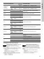
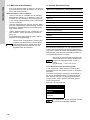
Sensor type
Measuring
parameter
Sensor
Amperometric
sensor (disc)
Cl
2
, ClO
2
91835237
(314-011)
O
3
96687714
(314-013)
Potentiostatic
sensor
Cl
2
96732268
(314-021)
NH
3
95700839
(314-031)
ClO
2
95700837
(314-041)
HCl
95700840
(314-061)
O
3
95700838
(314-071)
Caution
The Conex
®
DIA-G cannot be used for
measuring a gas concentration
continuously or for control according to the
German MAK standard regarding
maximum allowable concentration. Use
only calibrated gas measuring devices for
measuring gas concentration.
Ensure a sufficient safety level when
setting the limit values for the
Conex
®
DIA-G.
Warning
Other applications are not approved and
not permitted. Grundfos cannot be held
liable for any damage resulting from
incorrect use.

English (GB)
8
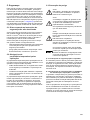
5. Safety
This manual contains general instructions that must
be observed during installation, operation and
maintenance. This manual must therefore be read by
the installation engineer and the relevant qualified
personnel/operators prior to installation and start-up
and must be available at the installation location of
the Conex
®
DIA-G at all times.
It is not only the general safety instructions
described in this section 5. Safety that must be
observed, but all special safety instructions that are
provided in the other sections.
5.1 Risks when safety instructions are not
observed
If safety instructions are not observed, it may result
in personal injury or damage to the Conex
®
DIA-G. If
safety instructions are not observed, this may lead to
the loss of any claims for damages.
If individual safety instructions are not observed, this
may cause for example the following damage:
• failure of specified methods for recording gas
concentrations and secondary safety equipment
• harm to humans from exposure to electrical,
mechanical and chemical influences.
5.2 Obligations of the owner/operations
manager
The owner/operations manager must ensure that
persons working with the described device fulfil
these requirements:
• They are acquainted with the regulations
concerning working safety and accident
prevention.
• They have been trained in use of the device.
• They have read and understood the warning
information and handling symbols.
The owner/operations manager is also responsible
for ensuring that this manual is kept in the immediate
vicinity of the device and is always available for the
operating personnel and that the local safety
regulations are observed when setting the limit
values for the sensors.
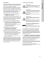
5.3 Avoidance of danger
5.3.1 Safety instructions for the operator
Damage caused by electrical energy must be
prevented. For more details, see for example the
regulations of the VDE, German Association for
Electrical, Electronic and Information Technologies,
and the local power supply company.
5.3.2 Safety instructions for maintenance,
inspection and installation work
The operator is responsible for ensuring that all
maintenance, inspection and installation work is
carried out by authorised and qualified personnel,
who have been adequately trained by reading the
installation and operating instructions.
All safety and protective equipment must be
immediately restarted or put into operation once
work is complete.
Observe the points described in the initial start-up
section prior to subsequent start-up.
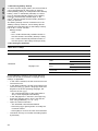
Warning
Do not use the device for monitoring
constant concentrations. The device is
designed for detecting leaks.
Warning
Installation and connection of the device
and the associated supplementary
components must only be carried out by
qualified specialists!
The local safety regulations must be
observed!
Warning
Switch off the power supply before
connecting the power supply cable and
relay contacts!
Do not dismantle the device! Maintenance
and repairs must only be carried out by
authorised specialists!
Caution
The mounting location must be selected so
that the housing is not subjected to
mechanical loading.
Check that all settings are correct before
starting up the device!

English (GB)
9
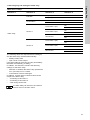
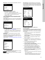
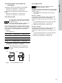
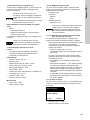
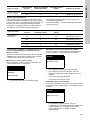
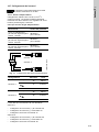
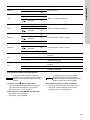
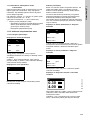
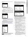
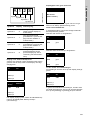
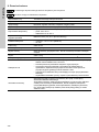
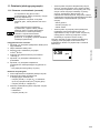
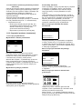
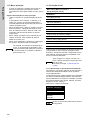
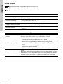
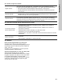
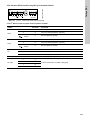
6. Identification
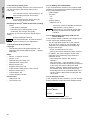
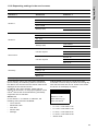
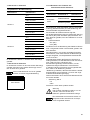
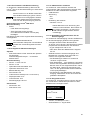
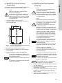
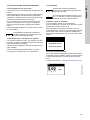
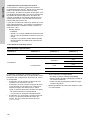
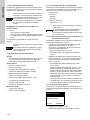
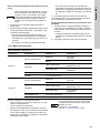
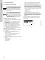
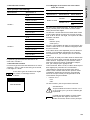
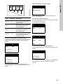
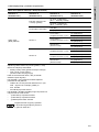
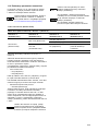
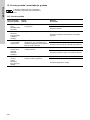
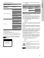
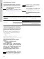
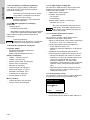
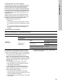
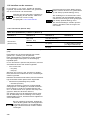
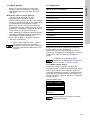
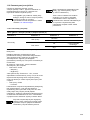
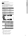
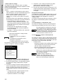
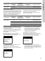
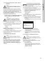
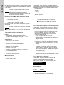
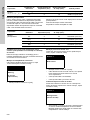
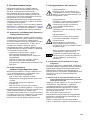
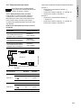
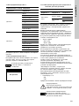
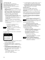
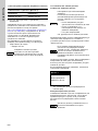
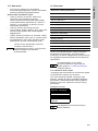
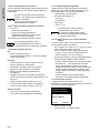
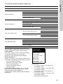
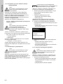
6.1 Nameplate
Fig. 1 Nameplate, Conex
®
DIA-G
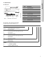
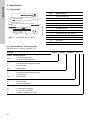
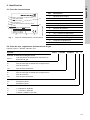
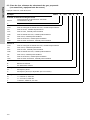
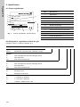
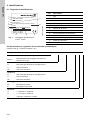
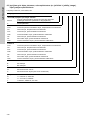
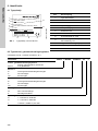
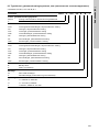
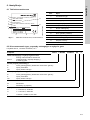
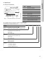
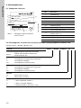
6.2 Type key, gas warning controllers
Example: DIA-G, 1-D/A/HC 2-D/A/HC, W-J
TM04 1259 0509
DIA-G, 1-D/A/HC 2-D/A/HC, W-J
308-2000-10012
S/N: 08/11221
Conex DIA-G
110-240V 50/60Hz 24V/DC, 30 VA,
IP 65
96732266P1108060808565
1
2
3
4
5
7
8
9
10
11
12
6
Pos. Description
1 Type designation
2 Model
3 Product
4 Voltage [V]
5 Frequency [Hz]
6 Product number
7 Country of origin
8 Year and week of production
9 Marks of approval, CE mark, etc.
10 Power consumption [VA]
11 Enclosure class
12 Serial number
Example: DIA-G 1-D/A/HC 2-D/A/HC W -J
Conex
®
gas warning system
DIA-G
Dosing Instrumentation Advanced
with gas detection
Sensor 1
D Chlorine gas/chlorine dioxide gas/ozone gas
A Ammonia gas
HC Hydrochloric acid gas
Sensor 2
D Chlorine gas/chlorine dioxide gas/ozone gas
A Ammonia gas
HC Hydrochloric acid gas
Mounting
W Wall-mounted
P Panel-mounted
Voltage
G 1 x 230/240 V, 50/60 Hz
H 1 x 115/120 V, 50/60 Hz
J 110-240 V, 50/60 Hz, 24 VDC

English (GB)
10
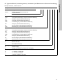
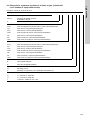
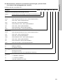
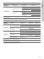
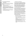
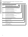
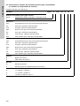
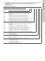
6.3 Type key, gas warning systems, prepacked (with sensors and sensor equipment)
Example: DIA-G-P, CLP-OP-B, W-J
Example: DIA-G -P. CLP- OP- B. W -J
Conex
®
gas warning system
DIA-G Dosing Instrumentation Advanced with gas detection
PPrepacked
Sensor 1
CCA Chlorine gas/chlorine dioxide gas, amperometric measurement
OA Ozone gas, amperometric measurement
CLP Chlorine gas, potentiostatic measurement
CDP Chlorine dioxide gas, potentiostatic measurement
OP Ozone gas, potentiostatic measurement
AP Ammonia gas, potentiostatic measurement
HCP Hydrochloric acid gas, potentiostatic measurement
Sensor 2
CCA Chlorine gas/chlorine dioxide gas, amperometric measurement
OA Ozone gas, amperometric measurement
CLP Chlorine gas, potentiostatic measurement
CDP Chlorine dioxide gas, potentiostatic measurement
OP Ozone gas, potentiostatic measurement
AP Ammonia gas, potentiostatic measurement
HCP Hydrochloric acid gas, potentiostatic measurement
Option
B Battery backup
X No battery backup
Mounting
W Wall-mounted
P Panel-mounted (not available at the moment)
Voltage
G 1 x 230/240 V, 50/60 Hz
H 1 x 115/120 V, 50/60Hz
J 110-240 V, 50/60 Hz, 24 VDC

English (GB)
11
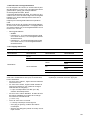
7. Product description and
accessories
This universal device offers high-precision
measuring of chlorine, chlorine dioxide, ozone,
ammonia or hydrochloric acid.
• comprehensive limit value functions
• comprehensive alarm functions
• logbook function: chronological recording of key
events with date and time
• user coding function as a means of protection
against access by unauthorised persons and for
system administration
• error message function for indication of
non-functioning sensors
• automatic monitoring of the sensor service life
with warnings about sensors that require
renewal.
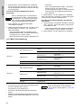
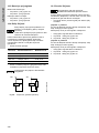
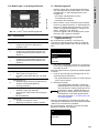
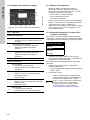
7.1 General description
The Conex
®
DIA-G is a gas warning controller for
monitoring gas concentrations, for example in
storage or dosing rooms. With a maximum of two
independently connected sensors, the gas
concentration of chlorine, ozone, chlorine dioxide,
hydrochloric acid or ammonia can be displayed and
monitored. Amperometric sensors (sensor discs) can
be connected directly to the Conex
®
DIA-G, and
potentiostatic sensors can be connected to a
preceding Conex
®
DIA-G sensor interface.
Each of the two sensors is provided with electrically
isolated current outputs (potential-free to power
supply) to output the measured concentration, two
electrically isolated limit value transmitters and an
alarm relay to control the warning and safety
equipment.
The Conex
®
DIA-G meets the high safety
requirements through permanent sensor monitoring,
alarm relays and optional backup mode (connection
of an external backup battery for supplying power to
the Conex
®
DIA-G in case of short-term power
supply interruptions).
How the system operates
• The gas sensors generate a current which is
proportional to the gas concentration in the air.
• The Conex
®
DIA-G gas warning controller
– amplifies the sensor current
– triggers an initial warning, for example when
the first limit value is exceeded
– activates the relevant warning and safety
equipment when the second limit value is
exceeded
– outputs the measured concentration at both
sensors as a 0 (4) - 20 mA signal via the
current outputs (for example for recording).

English (GB)
12
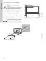
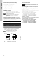
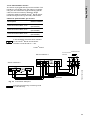
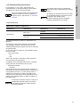
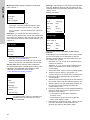
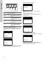
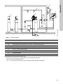
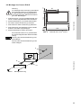
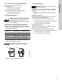
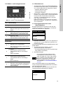
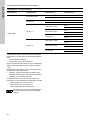
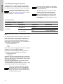
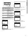
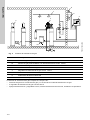
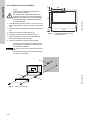
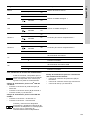
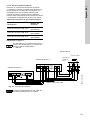
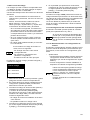
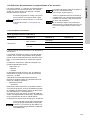
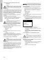
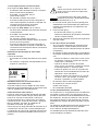
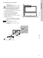
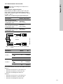
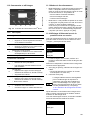
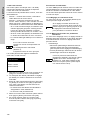
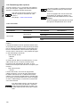
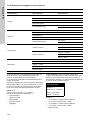
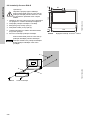
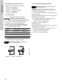
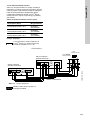
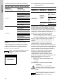
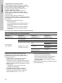
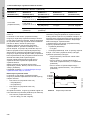
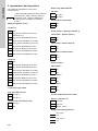
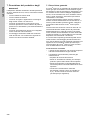
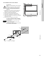
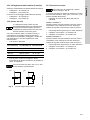
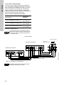
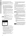
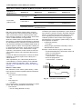
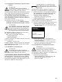
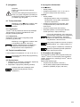
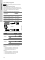
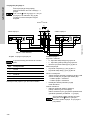
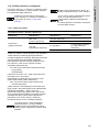
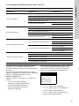
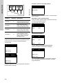
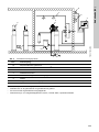
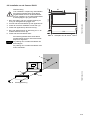
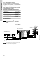
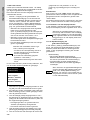
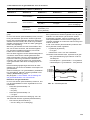
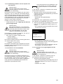
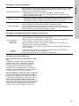
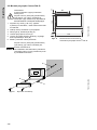
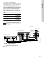
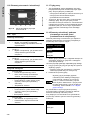
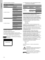
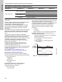
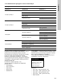
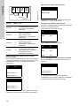
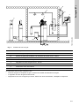
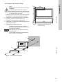
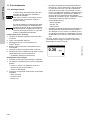
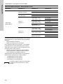
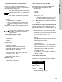
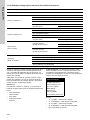
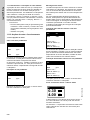
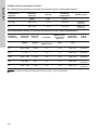
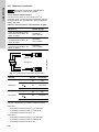
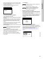
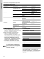
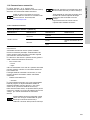
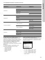
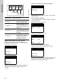
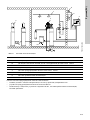
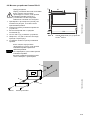
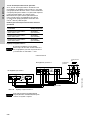
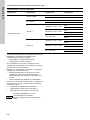
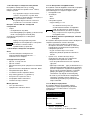
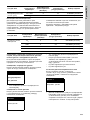
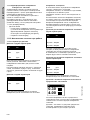
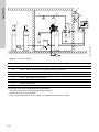
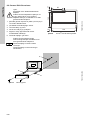
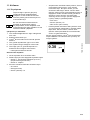
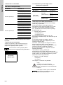
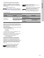
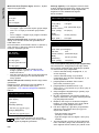
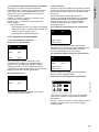
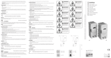
Fig. 2 Gas warning system
The complete gas warning system comprises:
• gas sensors in the gas container and gas dosing unit area
• the Conex
®
DIA-G gas warning controller
• warning and safety equipment: horn, flashing warning system, sprinkling installation.
TM03 7022 4506
4
6
5
7
3
2
1b
1a
Conex DIA-G
Sensor 1
Sensor 2
OKEsc
Alarm
Pos. Description
1a Amperometric gas sensor
1b Potentiostatic gas sensor with Conex
®
DIA-G sensor interface
2 Gas container
3 Gas dosing unit
4 Conex
®
DIA-G gas warning controller
5Horn
6 Flashing warning system
7 Sprinkling installation

English (GB)
13
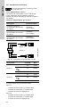
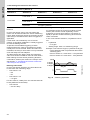
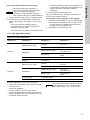
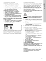
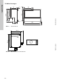
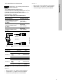
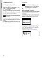
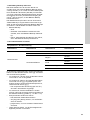
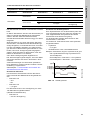
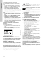
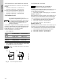
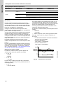
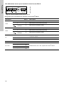
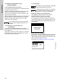
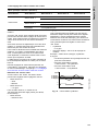
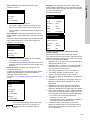
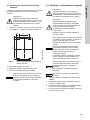
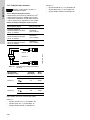
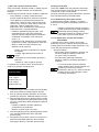
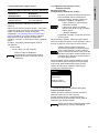
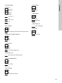
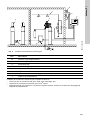
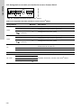
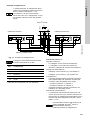
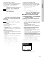
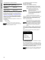
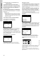
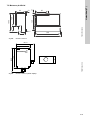
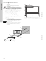
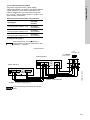
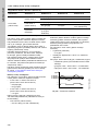
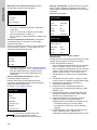
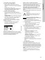
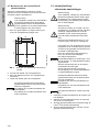
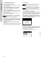
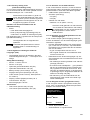
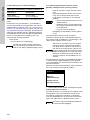
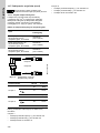
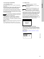
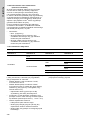
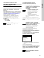
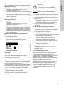
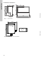
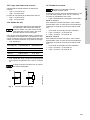
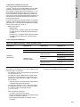
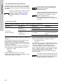
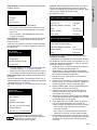
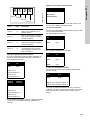
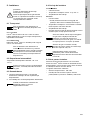
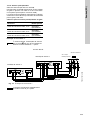
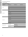
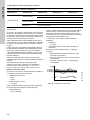
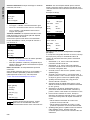
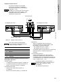
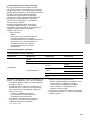
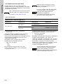
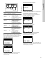
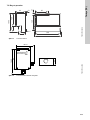
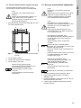
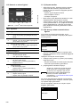
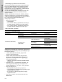
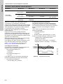
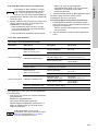
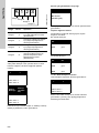
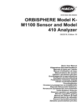
7.2 Dimensional sketches
Fig. 3 Conex
®
DIA-G
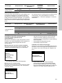
Fig. 4 Conex
®
DIA-G sensor interface
TM03 7023 4506
59
125
84
59.5
184.5
212
198
10
145
27
99
Ø 4.5
TM03 7024 4506
120
146.5
101.5
80
42

English (GB)
14
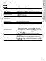
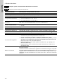
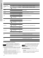
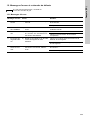
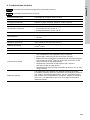
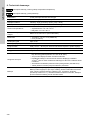
8. Technical data
Caution
Observe the permissible temperature range of the sensors!
Note
Observe the accuracy of the sensor!
Electronics 16-bit microprocessor technology
Display Backlit plain-text display
Display languages German, English, French, Spanish, Russian and Polish
Indication mode In ppm for measured values of both sensors
Permissible temperatures
Conex
®
DIA-G and sensor interface (without sensor):
• operation: 0 to +40 °C
• storage: 0 to +65 °C
Permissible relative air
humidity
Maximum 90 % at 40 °C (no condensation)
Power supply
• 110-240 V - 10 %/+ 10 % (50/60 Hz)
• 24 VDC
Power consumption Approximately 30 VA
Material (enclosure) ABS, resistant to chemicals
Enclosure class IP65 for Conex
®
DIA-G wall-mounting enclosure and sensor interface
Weight Approximately 1.5 kg
Connections Screw terminals for cables up to maximum 2.5 mm
2
Safety functions
• Permanent sensor monitoring or automatic sensor test, interval between
tests adjustable from 0.5 to 30 days
• Wire breakage monitoring of all current outputs
• Optional backup battery with backup indication on the display, allowing
Conex
®
DIA-G to work for at least one hour after power failure
• Automatic adjustment of data specific to the sensor (for example
calibration data)
• Display of the sensor exchange intervals with a plain-text message
Backup battery
All devices can be equipped with an external backup battery as an option.
The backup battery supplies the gas warning controller, including the
electrically isolated relays, but no external devices (for example signal
lamp, aeration, sprinkler system, etc.). The battery lasts for about one hour
after power supply failure.

English (GB)
15
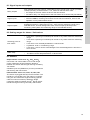
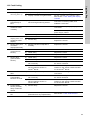
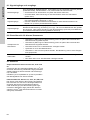
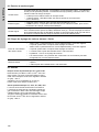
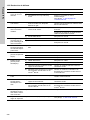
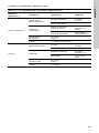
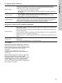
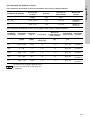
8.1 Signal inputs and outputs
8.2 Setting ranges for alarms / limit values
8.3 Sensors
Amperometric sensor disc Cl
2
, ClO
2
and O
3
Connection via 2-wire cable 0.5 mm
2
with single
screen. Maximum length (maximum distance
between the sensor disc and gas warning controller):
100 metres.
91835237 (314-011)/96687714 (314-013) include the
wall housing with sensor disc.
Potentiostatic sensor Cl
2
, ClO
2
, O
3
, NH
3
, HCl
The sensor is plugged directly into the interface. The
interface is connected to the gas warning controller
using a 4-wire cable with single screening (special
cable for CAN connections). Maximum length
(maximum distance between Conex
®
DIA-G sensor
interface and gas warning controller): 500 metres.
Relay outputs
Five potential-free relay outputs, switchable to NO (normally open) or NC (normally
closed) (fail safe); maximum 250 V / 6 A, maximum 550 VA ohmic load:
• two relays for the limit values of each of the two sensors
• one alarm relay; free assignment to the limit values or to sensor test (see below)
Signal inputs
• Two measured value inputs (for amperometric sensors 1 and 2)
• Internal CANBus, including connections for two sensor interfaces, each for the
operation of one potentiostatic sensor
Signal outputs
Two potential-free current outputs (0) 4 - 20 mA, maximum load of 500 Ω, with cable
breakage monitoring; assignment of 0 (4) - 20 mA to the measuring range of the
selected sensor, or linear assignment of the current output (0-20 mA) to the
measuring value (within the measuring range of the selected sensor)
Switching point for
limit values
• Limit value 1 (warning if exceeded) can be set to any value within the measuring
range.
• Limit value 2 (warning if exceeded) can be set to any value within the measuring
range.
• Limit value 2 can be delayed between 0-180 seconds.
• Hysteresis: 0-50 % of measuring range.
• Limit value 1 and 2 can be acknowledged. The acknowledgement is stored in a
list of events.
Alarm relay
• The alarm relay can be freely assigned to the limit values and/or the sensor test.
• The alarm can be delayed between 0-180 seconds.

English (GB)
16
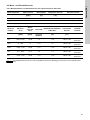
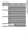
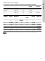
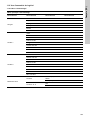
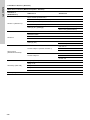
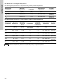
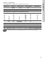
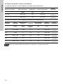
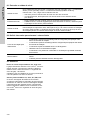
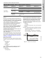
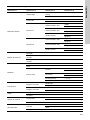
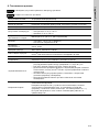
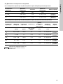
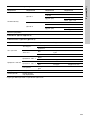
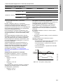
8.4 Measuring and setting ranges
8.4.1 Measuring parameter and working range for amperometric sensors
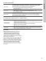
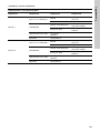
8.4.2 Measuring parameter and working range for potentiostatic sensors
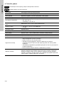
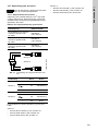
Measuring parameter Measuring range Accuracy Temperature range Product number
[ppm] [%] [°C]
Cl
2
, ClO
2
0.00 - 5.00 ± 10 +5 to +45
91835237
(314-011)
O
3
0.00 - 5.00 ± 10 +5 to +45
96687714
(314-013)
Measuring
parameter
Measuring
range
Resolution
at 20 °C
Linearity
Sensitivity drift
per 6 months
Temperature
range
Product
number
[ppm] [ppm]
[%] of
full scale
[%] [°C]
Cl
2
0.00 - 20.00 < 0.05 < 5 < 10 -20 to +40
96732268
(314-021)
NH
3
0 - 100 < 1 < 10 < 5 -20 to +40
95700839
(314-031)
ClO
2
0.00 - 1.00 < 0.03 < 10 < 10 -20 to +40
95700837
(314-041)
HCl 0.0 - 30.0 < 0.7 < 5 < 3 -20 to +40
95700840
(314-061)
O
3
0.00 - 1.00 < 0.02 < 10 < 10 -20 to +40
95700838
(314-071)
Note
The measuring ranges depend on the set sensors and cannot be modified.

English (GB)
17
9. Installation
9.1 Transport
9.1.1 Delivery
The Conex
®
DIA-G is delivered in a cardboard box.
Leave the device in the packaging during transport
and intermediate storage.
9.1.2 Return
Return the Conex
®
DIA-G in its original packaging or
equivalent.
9.2 Intermediate storage
Permissible storage temperature: -20 °C to +65 °C.
9.3 Unpacking
1. Check the device for damage. Install as soon as
possible after unpacking.
2. Do not install or connect damaged devices!
9.4 Installation requirements
Conex
®
DIA-G
• Dry room
• Room temperature: 0 °C to +40 °C
• Vibration-free location.
Sensors
• Dry room.
– Avoid the sensor getting wet! Make sure to
locate it outside the range of the sprinkling
installation.
• Room temperature according to the technical
data for the relevant sensor.
• Vibration-free location.
• Protect the sensor from direct heat, sunlight and
strong draughts!
9.5 Installation notes
Amperometric sensor discs are connected directly to
the Conex
®
DIA-G. If potentiostatic sensors are
used, one Conex
®
DIA-G sensor interface per
sensor is required.
Maximum cable lengths:
• Amperometric sensors: 100 metres
• DIA-G sensor interface for potentiostatic sensors
(CANBus connection): 500 metres.
Warning
Before assembling, disconnect the power
supply!
Enclosure class IP65 is only guaranteed if
the terminal covers are closed and the
appropriate cable glands or dummy caps
fitted.
Caution
Risk of malfunction or damage to the
Conex
®
DIA-G! Do not drop the device.
Caution
Risk of malfunction or damage to the
Conex
®
DIA-G! Grundfos accepts no
liability for damage caused by incorrect
transportation or missing or unsuitable
packaging of the device!
Note
For information on storing the sensors, see
the manual of the gas sensors.
Note
Retain the packing material or dispose of it
according to local regulations.
Caution
The sensor must be replaced after a gas
eruption that has exceeded the measuring
range. Do not expose the sensor to a
higher gas concentration, even during
start-up and test.
Caution
Gas sensors should not be mounted close
to major sources of interference such as
large machines, etc.
Caution
If these assembly requirements are not
observed, there may be damage to the
measuring device or incorrect
measurements!

English (GB)
18
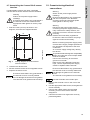
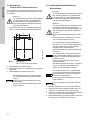
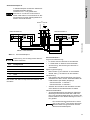
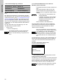
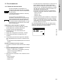
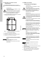
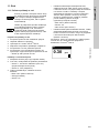
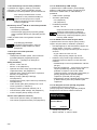
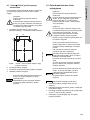
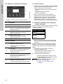
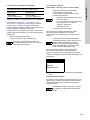
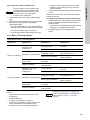
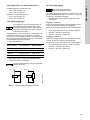
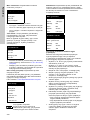
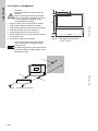
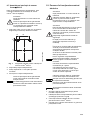
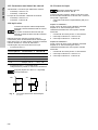
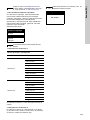
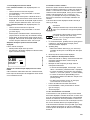
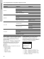
9.6 Installation of the Conex
®
DIA-G
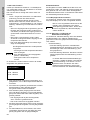
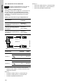
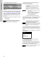
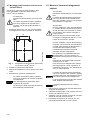
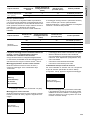
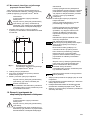
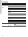
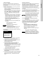
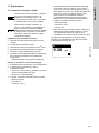
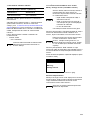
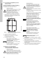
1. Drill three holes (∅8 mm) as shown in the
diagram, and insert the supplied dowels.
2. Unscrew the terminal cover on the device.
3. Tighten the upper middle screw (A).
4. Place the device on this screw (A).
5. Secure the device through the enclosure using
the two other screws (B).
6. Replace the terminal cover.
Fig. 5 Drilling diagram of the Conex
®
DIA-G
Fig. 6 Mounting drawing
Warning
Switch off the power supply before
installing!
Enclosure class IP65 is only guaranteed if
the terminal covers are closed and the
appropriate cable glands or dummy caps
fitted.
Caution
Enclosure class IP65 is only guaranteed if
the terminal cover is correctly sealed!
Do not damage the terminal cover gasket!
The terminal cover gasket must fit exactly!
TM03 7025 4506
198
145
27
10.5
99
TM03 7026 4506
B
B
A
Conex DIA-G
Sensor 1
Sensor 2
OKEsc
Alarm

English (GB)
19
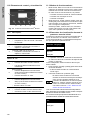
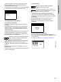
9.7 Assembling the Conex
®
DIA-G sensor
interface
If potentiostatic sensors are used, a separate
Conex
®
DIA-G sensor interface must be installed.
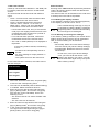
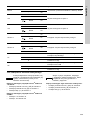
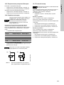
1. Drill four holes (∅6 mm) as shown in the
diagram, and insert the supplied dowels.
Fig. 7 Drilling diagram of Conex
®
DIA-G
sensor interface
2. Unscrew the device cover.
3. Secure the device with the four supplied screws.
4. Replace the device cover.
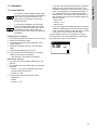
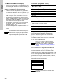
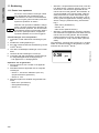
10. Commissioning/electrical
connections
1. Remove the terminal cover on the front of the
device.
2. Use the appropriate cable entries, and tighten the
screws carefully.
3. Connect the cables used to the terminals
according to the Conex
®
DIA-G terminal
assignment.
4. Close the terminal cover again with correctly
positioned gasket.
Warning
Switch off the power supply before
installing!
Enclosure class IP65 is only guaranteed if
the terminal covers are closed and the
appropriate cable glands or dummy caps
fitted.
TM03 7027 4506
Caution
Enclosure class IP65 is only guaranteed if
the terminal cover is correctly sealed!
Do not damage the terminal cover gasket!
The terminal cover gasket must fit exactly!
108
6
15
50
Warning
Switch off the power supply before
installing!
Enclosure class IP65 is only guaranteed
with the front panel of the terminals
enclosure closed and with appropriate
cable glands or dummy caps.
Warning
Disconnect the power supply before
connecting the power supply cable and the
relay contacts! For safety reasons, the
protective conductor must be connected
correctly!
Observe the local safety regulations!
Protect the cable connections and plugs
against corrosion and humidity.
Caution
Before connecting the power supply cable,
check that the supply voltage specified on
the nameplate corresponds to the local
conditions!
An incorrect supply voltage may destroy
the device!
To guarantee electromagnetic compatibility
(EMC), the input and current output cables
must be screened.
Connect the screening to the screen
ground on one side!
Refer to the wiring diagram! Route the
input, current output and power supply
cables in separate cable channels.
Caution
Enclosure class IP65 is only guaranteed if
the terminal cover is correctly sealed! Do
not damage the gasket on the terminal
cover!
The terminal cover gasket must fit exactly!
Note
Unused terminals must remain open.

English (GB)
20
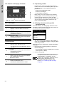
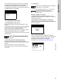
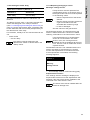
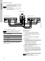
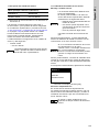
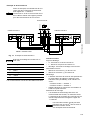
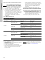
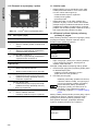
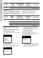
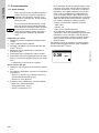
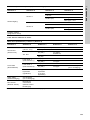
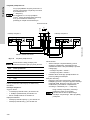
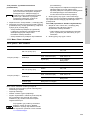
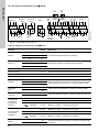
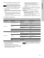
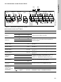
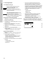
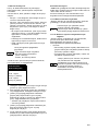
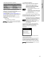
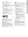
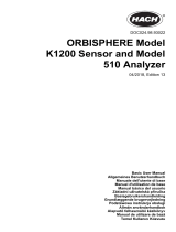
10.1 Conex
®
DIA-G terminal assignment
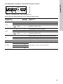
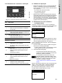
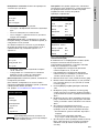
Fig. 8 Conex
®
DIA-G terminal
Key for Conex
®
DIA-G terminal diagram
TM04 8396 1411
1
S1
0
1
S2
0
Main in
Sensor 1
SP2
Sensor 2
SP2
Alarm
Input
Bat
24 V
CAN
Sensor
CAN
Interface
Reset
mAmA
Sensor 1
out SP1SP1
NO
NC
24V Out
Sensor
Interface
Bat
ok
mAmA
Sensor 2
+
+++++
+
–
+
––
–––––
LL
LL
HH
HH
LNPE
LNPE
12
12
1
2
3
4
5
6
7
8
9
10
11
12
13
14
15
16
17
18
19
20
21
22
23
24
25
26
27
28
29
30
31
32
33
34
35
36
37
38
39
40
41
42
43
44
45
46
47
48
49
50
Assignment Terminal Description
Main in
L1
Power supply connectionN3
PE 5
Main out
L2
Supply for electrically isolated contactsN4
PE 6
Sensor 1/SP 1 7, 8 Limit value relay (setpoint) 1, sensor 1
Sensor 1/SP 2 9, 10 Limit value relay (setpoint) 2, sensor 1
Sensor 2/SP 1 11, 12 Limit value relay (setpoint) 1, sensor 2
Sensor 2/SP 2 13, 14 Limit value relay (setpoint) 2, sensor 2
Alarm
NO 18
Alarm relay with terminal 15, 16 and terminal 18:
normally open contact, or terminal 17: normally
closed contact
NC 17
15, 16
Input Bat
24 V
+19
Input for external battery supply (UPS)
-20
24 V Out Sensor
Interface
+21
24 V supply output for sensor interface
-22
CAN sensor
(sensor interface
connection)
L 23, 24 Terminal 23: input... or terminal 24: output...
H 25, 26 Terminal 25: input... or terminal 26: output...
Screen
27, 28 Terminal 27: input... or terminal 28: output...
CAN interface
(CANBus
connection)
L 29, 30 Terminal 29: input... or terminal 30: output...
H 31, 32 Terminal 31: input... or terminal 32: output...
Screen
33, 34 Terminal 33: input... or terminal 34: output...
Reset
+35
External alarm acknowledgement using switching
contact
-36
Sayfa yükleniyor...
Sayfa yükleniyor...
Sayfa yükleniyor...
Sayfa yükleniyor...
Sayfa yükleniyor...
Sayfa yükleniyor...
Sayfa yükleniyor...
Sayfa yükleniyor...
Sayfa yükleniyor...
Sayfa yükleniyor...
Sayfa yükleniyor...
Sayfa yükleniyor...
Sayfa yükleniyor...
Sayfa yükleniyor...
Sayfa yükleniyor...
Sayfa yükleniyor...
Sayfa yükleniyor...
Sayfa yükleniyor...
Sayfa yükleniyor...
Sayfa yükleniyor...
Sayfa yükleniyor...
Sayfa yükleniyor...
Sayfa yükleniyor...
Sayfa yükleniyor...
Sayfa yükleniyor...
Sayfa yükleniyor...
Sayfa yükleniyor...
Sayfa yükleniyor...
Sayfa yükleniyor...
Sayfa yükleniyor...
Sayfa yükleniyor...
Sayfa yükleniyor...
Sayfa yükleniyor...
Sayfa yükleniyor...
Sayfa yükleniyor...
Sayfa yükleniyor...
Sayfa yükleniyor...
Sayfa yükleniyor...
Sayfa yükleniyor...
Sayfa yükleniyor...
Sayfa yükleniyor...
Sayfa yükleniyor...
Sayfa yükleniyor...
Sayfa yükleniyor...
Sayfa yükleniyor...
Sayfa yükleniyor...
Sayfa yükleniyor...
Sayfa yükleniyor...
Sayfa yükleniyor...
Sayfa yükleniyor...
Sayfa yükleniyor...
Sayfa yükleniyor...
Sayfa yükleniyor...
Sayfa yükleniyor...
Sayfa yükleniyor...
Sayfa yükleniyor...
Sayfa yükleniyor...
Sayfa yükleniyor...
Sayfa yükleniyor...
Sayfa yükleniyor...
Sayfa yükleniyor...
Sayfa yükleniyor...
Sayfa yükleniyor...
Sayfa yükleniyor...
Sayfa yükleniyor...
Sayfa yükleniyor...
Sayfa yükleniyor...
Sayfa yükleniyor...
Sayfa yükleniyor...
Sayfa yükleniyor...
Sayfa yükleniyor...
Sayfa yükleniyor...
Sayfa yükleniyor...
Sayfa yükleniyor...
Sayfa yükleniyor...
Sayfa yükleniyor...
Sayfa yükleniyor...
Sayfa yükleniyor...
Sayfa yükleniyor...
Sayfa yükleniyor...
Sayfa yükleniyor...
Sayfa yükleniyor...
Sayfa yükleniyor...
Sayfa yükleniyor...
Sayfa yükleniyor...
Sayfa yükleniyor...
Sayfa yükleniyor...
Sayfa yükleniyor...
Sayfa yükleniyor...
Sayfa yükleniyor...
Sayfa yükleniyor...
Sayfa yükleniyor...
Sayfa yükleniyor...
Sayfa yükleniyor...
Sayfa yükleniyor...
Sayfa yükleniyor...
Sayfa yükleniyor...
Sayfa yükleniyor...
Sayfa yükleniyor...
Sayfa yükleniyor...
Sayfa yükleniyor...
Sayfa yükleniyor...
Sayfa yükleniyor...
Sayfa yükleniyor...
Sayfa yükleniyor...
Sayfa yükleniyor...
Sayfa yükleniyor...
Sayfa yükleniyor...
Sayfa yükleniyor...
Sayfa yükleniyor...
Sayfa yükleniyor...
Sayfa yükleniyor...
Sayfa yükleniyor...
Sayfa yükleniyor...
Sayfa yükleniyor...
Sayfa yükleniyor...
Sayfa yükleniyor...
Sayfa yükleniyor...
Sayfa yükleniyor...
Sayfa yükleniyor...
Sayfa yükleniyor...
Sayfa yükleniyor...
Sayfa yükleniyor...
Sayfa yükleniyor...
Sayfa yükleniyor...
Sayfa yükleniyor...
Sayfa yükleniyor...
Sayfa yükleniyor...
Sayfa yükleniyor...
Sayfa yükleniyor...
Sayfa yükleniyor...
Sayfa yükleniyor...
Sayfa yükleniyor...
Sayfa yükleniyor...
Sayfa yükleniyor...
Sayfa yükleniyor...
Sayfa yükleniyor...
Sayfa yükleniyor...
Sayfa yükleniyor...
Sayfa yükleniyor...
Sayfa yükleniyor...
Sayfa yükleniyor...
Sayfa yükleniyor...
Sayfa yükleniyor...
Sayfa yükleniyor...
Sayfa yükleniyor...
Sayfa yükleniyor...
Sayfa yükleniyor...
Sayfa yükleniyor...
Sayfa yükleniyor...
Sayfa yükleniyor...
Sayfa yükleniyor...
Sayfa yükleniyor...
Sayfa yükleniyor...
Sayfa yükleniyor...
Sayfa yükleniyor...
Sayfa yükleniyor...
Sayfa yükleniyor...
Sayfa yükleniyor...
Sayfa yükleniyor...
Sayfa yükleniyor...
Sayfa yükleniyor...
Sayfa yükleniyor...
Sayfa yükleniyor...
Sayfa yükleniyor...
Sayfa yükleniyor...
Sayfa yükleniyor...
Sayfa yükleniyor...
Sayfa yükleniyor...
Sayfa yükleniyor...
Sayfa yükleniyor...
Sayfa yükleniyor...
Sayfa yükleniyor...
Sayfa yükleniyor...
Sayfa yükleniyor...
Sayfa yükleniyor...
Sayfa yükleniyor...
Sayfa yükleniyor...
Sayfa yükleniyor...
Sayfa yükleniyor...
Sayfa yükleniyor...
Sayfa yükleniyor...
Sayfa yükleniyor...
Sayfa yükleniyor...
Sayfa yükleniyor...
Sayfa yükleniyor...
Sayfa yükleniyor...
Sayfa yükleniyor...
Sayfa yükleniyor...
Sayfa yükleniyor...
Sayfa yükleniyor...
Sayfa yükleniyor...
Sayfa yükleniyor...
Sayfa yükleniyor...
Sayfa yükleniyor...
Sayfa yükleniyor...
Sayfa yükleniyor...
Sayfa yükleniyor...
Sayfa yükleniyor...
Sayfa yükleniyor...
Sayfa yükleniyor...
Sayfa yükleniyor...
Sayfa yükleniyor...
Sayfa yükleniyor...
Sayfa yükleniyor...
Sayfa yükleniyor...
Sayfa yükleniyor...
Sayfa yükleniyor...
Sayfa yükleniyor...
Sayfa yükleniyor...
Sayfa yükleniyor...
Sayfa yükleniyor...
Sayfa yükleniyor...
Sayfa yükleniyor...
Sayfa yükleniyor...
Sayfa yükleniyor...
Sayfa yükleniyor...
Sayfa yükleniyor...
Sayfa yükleniyor...
Sayfa yükleniyor...
Sayfa yükleniyor...
Sayfa yükleniyor...
Sayfa yükleniyor...
Sayfa yükleniyor...
Sayfa yükleniyor...
Sayfa yükleniyor...
Sayfa yükleniyor...
Sayfa yükleniyor...
Sayfa yükleniyor...
Sayfa yükleniyor...
Sayfa yükleniyor...
Sayfa yükleniyor...
Sayfa yükleniyor...
Sayfa yükleniyor...
Sayfa yükleniyor...
Sayfa yükleniyor...
Sayfa yükleniyor...
Sayfa yükleniyor...
Sayfa yükleniyor...
Sayfa yükleniyor...
Sayfa yükleniyor...
Sayfa yükleniyor...
Sayfa yükleniyor...
Sayfa yükleniyor...
Sayfa yükleniyor...
Sayfa yükleniyor...
Sayfa yükleniyor...
Sayfa yükleniyor...
Sayfa yükleniyor...
Sayfa yükleniyor...
Sayfa yükleniyor...
Sayfa yükleniyor...
Sayfa yükleniyor...
Sayfa yükleniyor...
Sayfa yükleniyor...
Sayfa yükleniyor...
Sayfa yükleniyor...
Sayfa yükleniyor...
Sayfa yükleniyor...
Sayfa yükleniyor...
Sayfa yükleniyor...
Sayfa yükleniyor...
Sayfa yükleniyor...
Sayfa yükleniyor...
Sayfa yükleniyor...
Sayfa yükleniyor...
Sayfa yükleniyor...
Sayfa yükleniyor...
Sayfa yükleniyor...
Sayfa yükleniyor...
Sayfa yükleniyor...
Sayfa yükleniyor...
Sayfa yükleniyor...
Sayfa yükleniyor...
Sayfa yükleniyor...
Sayfa yükleniyor...
Sayfa yükleniyor...
Sayfa yükleniyor...
Sayfa yükleniyor...
Sayfa yükleniyor...
Sayfa yükleniyor...
Sayfa yükleniyor...
Sayfa yükleniyor...
Sayfa yükleniyor...
Sayfa yükleniyor...
Sayfa yükleniyor...
Sayfa yükleniyor...
Sayfa yükleniyor...
Sayfa yükleniyor...
Sayfa yükleniyor...
Sayfa yükleniyor...
Sayfa yükleniyor...
Sayfa yükleniyor...
Sayfa yükleniyor...
Sayfa yükleniyor...
Sayfa yükleniyor...
Sayfa yükleniyor...
Sayfa yükleniyor...
Sayfa yükleniyor...
Sayfa yükleniyor...
Sayfa yükleniyor...
Sayfa yükleniyor...
Sayfa yükleniyor...
Sayfa yükleniyor...
Sayfa yükleniyor...
Sayfa yükleniyor...
Sayfa yükleniyor...
Sayfa yükleniyor...
Sayfa yükleniyor...
Sayfa yükleniyor...
Sayfa yükleniyor...
Sayfa yükleniyor...
Sayfa yükleniyor...
Sayfa yükleniyor...
Sayfa yükleniyor...
Sayfa yükleniyor...
Sayfa yükleniyor...
Sayfa yükleniyor...
Sayfa yükleniyor...
Sayfa yükleniyor...
Sayfa yükleniyor...
Sayfa yükleniyor...
Sayfa yükleniyor...
Sayfa yükleniyor...
Sayfa yükleniyor...
Sayfa yükleniyor...
Sayfa yükleniyor...
Sayfa yükleniyor...
Sayfa yükleniyor...
Sayfa yükleniyor...
Sayfa yükleniyor...
Sayfa yükleniyor...
Sayfa yükleniyor...
Sayfa yükleniyor...
Sayfa yükleniyor...
Sayfa yükleniyor...
Sayfa yükleniyor...
Sayfa yükleniyor...
Sayfa yükleniyor...
Sayfa yükleniyor...
Sayfa yükleniyor...
Sayfa yükleniyor...
Sayfa yükleniyor...
Sayfa yükleniyor...
Sayfa yükleniyor...
Sayfa yükleniyor...
Sayfa yükleniyor...
Sayfa yükleniyor...
Sayfa yükleniyor...
Sayfa yükleniyor...
Sayfa yükleniyor...
Sayfa yükleniyor...
Sayfa yükleniyor...
Sayfa yükleniyor...
Sayfa yükleniyor...
Sayfa yükleniyor...
Sayfa yükleniyor...
Sayfa yükleniyor...
Sayfa yükleniyor...
Sayfa yükleniyor...
Sayfa yükleniyor...
Sayfa yükleniyor...
Sayfa yükleniyor...
Sayfa yükleniyor...
Sayfa yükleniyor...
Sayfa yükleniyor...
Sayfa yükleniyor...
Sayfa yükleniyor...
Sayfa yükleniyor...
Sayfa yükleniyor...
Sayfa yükleniyor...
Sayfa yükleniyor...
Sayfa yükleniyor...
Sayfa yükleniyor...
Sayfa yükleniyor...
Sayfa yükleniyor...
Sayfa yükleniyor...
Sayfa yükleniyor...
Sayfa yükleniyor...
Sayfa yükleniyor...
Sayfa yükleniyor...
Sayfa yükleniyor...
Sayfa yükleniyor...
Sayfa yükleniyor...
Sayfa yükleniyor...
Sayfa yükleniyor...
Sayfa yükleniyor...
Sayfa yükleniyor...
Sayfa yükleniyor...
Sayfa yükleniyor...
Sayfa yükleniyor...
Sayfa yükleniyor...
Sayfa yükleniyor...
Sayfa yükleniyor...
Sayfa yükleniyor...
Sayfa yükleniyor...
Sayfa yükleniyor...
Sayfa yükleniyor...
Sayfa yükleniyor...
Sayfa yükleniyor...
Sayfa yükleniyor...
Sayfa yükleniyor...
Sayfa yükleniyor...
Sayfa yükleniyor...
Sayfa yükleniyor...
Sayfa yükleniyor...
Sayfa yükleniyor...
Sayfa yükleniyor...
Sayfa yükleniyor...
Sayfa yükleniyor...
Sayfa yükleniyor...
Sayfa yükleniyor...
Sayfa yükleniyor...
Sayfa yükleniyor...
Sayfa yükleniyor...
Sayfa yükleniyor...
Sayfa yükleniyor...
Sayfa yükleniyor...
Sayfa yükleniyor...
Sayfa yükleniyor...
Sayfa yükleniyor...
Sayfa yükleniyor...
Sayfa yükleniyor...
Sayfa yükleniyor...
Sayfa yükleniyor...
Sayfa yükleniyor...
Sayfa yükleniyor...
Sayfa yükleniyor...
Sayfa yükleniyor...
Sayfa yükleniyor...
Sayfa yükleniyor...
Sayfa yükleniyor...
Sayfa yükleniyor...
Sayfa yükleniyor...
Sayfa yükleniyor...
Sayfa yükleniyor...
Sayfa yükleniyor...
Sayfa yükleniyor...
Sayfa yükleniyor...
Sayfa yükleniyor...
Sayfa yükleniyor...
Sayfa yükleniyor...
Sayfa yükleniyor...
Sayfa yükleniyor...
Sayfa yükleniyor...
Sayfa yükleniyor...
Sayfa yükleniyor...
Sayfa yükleniyor...
Sayfa yükleniyor...
Sayfa yükleniyor...
Sayfa yükleniyor...
Sayfa yükleniyor...
Sayfa yükleniyor...
Sayfa yükleniyor...
Sayfa yükleniyor...
Sayfa yükleniyor...
Sayfa yükleniyor...
Sayfa yükleniyor...
Sayfa yükleniyor...
Sayfa yükleniyor...
Sayfa yükleniyor...
Sayfa yükleniyor...
Sayfa yükleniyor...
Sayfa yükleniyor...
Sayfa yükleniyor...
Sayfa yükleniyor...
Sayfa yükleniyor...
Sayfa yükleniyor...
Sayfa yükleniyor...
Sayfa yükleniyor...
Sayfa yükleniyor...
Sayfa yükleniyor...
Sayfa yükleniyor...
Sayfa yükleniyor...
Sayfa yükleniyor...
Sayfa yükleniyor...
Sayfa yükleniyor...
Sayfa yükleniyor...
Sayfa yükleniyor...
Sayfa yükleniyor...
Sayfa yükleniyor...
Sayfa yükleniyor...
Sayfa yükleniyor...
Sayfa yükleniyor...
Sayfa yükleniyor...
Sayfa yükleniyor...
Sayfa yükleniyor...
Sayfa yükleniyor...
Sayfa yükleniyor...
Sayfa yükleniyor...
Sayfa yükleniyor...
Sayfa yükleniyor...
Sayfa yükleniyor...
Sayfa yükleniyor...
Sayfa yükleniyor...
Sayfa yükleniyor...
Sayfa yükleniyor...
Sayfa yükleniyor...
Sayfa yükleniyor...
Sayfa yükleniyor...
Sayfa yükleniyor...
Sayfa yükleniyor...
Sayfa yükleniyor...
Sayfa yükleniyor...
Sayfa yükleniyor...
Sayfa yükleniyor...
Sayfa yükleniyor...
Sayfa yükleniyor...
Sayfa yükleniyor...
Sayfa yükleniyor...
Sayfa yükleniyor...
Sayfa yükleniyor...
Sayfa yükleniyor...
Sayfa yükleniyor...
Sayfa yükleniyor...
Sayfa yükleniyor...
Sayfa yükleniyor...
Sayfa yükleniyor...
Sayfa yükleniyor...
Sayfa yükleniyor...
Sayfa yükleniyor...
Sayfa yükleniyor...
Sayfa yükleniyor...
Sayfa yükleniyor...
Sayfa yükleniyor...
Sayfa yükleniyor...
Sayfa yükleniyor...
Sayfa yükleniyor...
Sayfa yükleniyor...
Sayfa yükleniyor...
Sayfa yükleniyor...
Sayfa yükleniyor...
Sayfa yükleniyor...
Sayfa yükleniyor...
Sayfa yükleniyor...
Sayfa yükleniyor...
Sayfa yükleniyor...
Sayfa yükleniyor...
Sayfa yükleniyor...
Sayfa yükleniyor...
Sayfa yükleniyor...
Sayfa yükleniyor...
Sayfa yükleniyor...
Sayfa yükleniyor...
Sayfa yükleniyor...
Sayfa yükleniyor...
Sayfa yükleniyor...
Sayfa yükleniyor...
Sayfa yükleniyor...
Sayfa yükleniyor...
Sayfa yükleniyor...
Sayfa yükleniyor...
Sayfa yükleniyor...
Sayfa yükleniyor...
Sayfa yükleniyor...
Sayfa yükleniyor...
Sayfa yükleniyor...
Sayfa yükleniyor...
Sayfa yükleniyor...
Sayfa yükleniyor...
Sayfa yükleniyor...
Sayfa yükleniyor...
Sayfa yükleniyor...
Sayfa yükleniyor...
Sayfa yükleniyor...
Sayfa yükleniyor...
Sayfa yükleniyor...
Sayfa yükleniyor...
Sayfa yükleniyor...
Sayfa yükleniyor...
Sayfa yükleniyor...
Sayfa yükleniyor...
Sayfa yükleniyor...
Sayfa yükleniyor...
Sayfa yükleniyor...
Sayfa yükleniyor...
Sayfa yükleniyor...
Sayfa yükleniyor...
Sayfa yükleniyor...
Sayfa yükleniyor...
Sayfa yükleniyor...
Sayfa yükleniyor...
Sayfa yükleniyor...
Sayfa yükleniyor...
Sayfa yükleniyor...
Sayfa yükleniyor...
Sayfa yükleniyor...
Sayfa yükleniyor...
Sayfa yükleniyor...
Sayfa yükleniyor...
Sayfa yükleniyor...
Sayfa yükleniyor...
Sayfa yükleniyor...
Sayfa yükleniyor...
Sayfa yükleniyor...
Sayfa yükleniyor...
Sayfa yükleniyor...
Sayfa yükleniyor...
Sayfa yükleniyor...
Sayfa yükleniyor...
Sayfa yükleniyor...
Sayfa yükleniyor...
Sayfa yükleniyor...
Sayfa yükleniyor...
Sayfa yükleniyor...
Sayfa yükleniyor...
Sayfa yükleniyor...
Sayfa yükleniyor...
Sayfa yükleniyor...
Sayfa yükleniyor...
Sayfa yükleniyor...
Sayfa yükleniyor...
Sayfa yükleniyor...
Sayfa yükleniyor...
Sayfa yükleniyor...
Sayfa yükleniyor...
Sayfa yükleniyor...
Sayfa yükleniyor...
Sayfa yükleniyor...
Sayfa yükleniyor...
Sayfa yükleniyor...
Sayfa yükleniyor...
Sayfa yükleniyor...
Sayfa yükleniyor...
Sayfa yükleniyor...
Sayfa yükleniyor...
Sayfa yükleniyor...
Sayfa yükleniyor...
Sayfa yükleniyor...
Sayfa yükleniyor...
Sayfa yükleniyor...
Sayfa yükleniyor...
Sayfa yükleniyor...
Sayfa yükleniyor...
Sayfa yükleniyor...
Sayfa yükleniyor...
Sayfa yükleniyor...
Sayfa yükleniyor...
Sayfa yükleniyor...
Sayfa yükleniyor...
Sayfa yükleniyor...
Sayfa yükleniyor...
Sayfa yükleniyor...
Sayfa yükleniyor...
Sayfa yükleniyor...
Sayfa yükleniyor...
Sayfa yükleniyor...
Sayfa yükleniyor...
Sayfa yükleniyor...
Sayfa yükleniyor...
Sayfa yükleniyor...
Sayfa yükleniyor...
-
 1
1
-
 2
2
-
 3
3
-
 4
4
-
 5
5
-
 6
6
-
 7
7
-
 8
8
-
 9
9
-
 10
10
-
 11
11
-
 12
12
-
 13
13
-
 14
14
-
 15
15
-
 16
16
-
 17
17
-
 18
18
-
 19
19
-
 20
20
-
 21
21
-
 22
22
-
 23
23
-
 24
24
-
 25
25
-
 26
26
-
 27
27
-
 28
28
-
 29
29
-
 30
30
-
 31
31
-
 32
32
-
 33
33
-
 34
34
-
 35
35
-
 36
36
-
 37
37
-
 38
38
-
 39
39
-
 40
40
-
 41
41
-
 42
42
-
 43
43
-
 44
44
-
 45
45
-
 46
46
-
 47
47
-
 48
48
-
 49
49
-
 50
50
-
 51
51
-
 52
52
-
 53
53
-
 54
54
-
 55
55
-
 56
56
-
 57
57
-
 58
58
-
 59
59
-
 60
60
-
 61
61
-
 62
62
-
 63
63
-
 64
64
-
 65
65
-
 66
66
-
 67
67
-
 68
68
-
 69
69
-
 70
70
-
 71
71
-
 72
72
-
 73
73
-
 74
74
-
 75
75
-
 76
76
-
 77
77
-
 78
78
-
 79
79
-
 80
80
-
 81
81
-
 82
82
-
 83
83
-
 84
84
-
 85
85
-
 86
86
-
 87
87
-
 88
88
-
 89
89
-
 90
90
-
 91
91
-
 92
92
-
 93
93
-
 94
94
-
 95
95
-
 96
96
-
 97
97
-
 98
98
-
 99
99
-
 100
100
-
 101
101
-
 102
102
-
 103
103
-
 104
104
-
 105
105
-
 106
106
-
 107
107
-
 108
108
-
 109
109
-
 110
110
-
 111
111
-
 112
112
-
 113
113
-
 114
114
-
 115
115
-
 116
116
-
 117
117
-
 118
118
-
 119
119
-
 120
120
-
 121
121
-
 122
122
-
 123
123
-
 124
124
-
 125
125
-
 126
126
-
 127
127
-
 128
128
-
 129
129
-
 130
130
-
 131
131
-
 132
132
-
 133
133
-
 134
134
-
 135
135
-
 136
136
-
 137
137
-
 138
138
-
 139
139
-
 140
140
-
 141
141
-
 142
142
-
 143
143
-
 144
144
-
 145
145
-
 146
146
-
 147
147
-
 148
148
-
 149
149
-
 150
150
-
 151
151
-
 152
152
-
 153
153
-
 154
154
-
 155
155
-
 156
156
-
 157
157
-
 158
158
-
 159
159
-
 160
160
-
 161
161
-
 162
162
-
 163
163
-
 164
164
-
 165
165
-
 166
166
-
 167
167
-
 168
168
-
 169
169
-
 170
170
-
 171
171
-
 172
172
-
 173
173
-
 174
174
-
 175
175
-
 176
176
-
 177
177
-
 178
178
-
 179
179
-
 180
180
-
 181
181
-
 182
182
-
 183
183
-
 184
184
-
 185
185
-
 186
186
-
 187
187
-
 188
188
-
 189
189
-
 190
190
-
 191
191
-
 192
192
-
 193
193
-
 194
194
-
 195
195
-
 196
196
-
 197
197
-
 198
198
-
 199
199
-
 200
200
-
 201
201
-
 202
202
-
 203
203
-
 204
204
-
 205
205
-
 206
206
-
 207
207
-
 208
208
-
 209
209
-
 210
210
-
 211
211
-
 212
212
-
 213
213
-
 214
214
-
 215
215
-
 216
216
-
 217
217
-
 218
218
-
 219
219
-
 220
220
-
 221
221
-
 222
222
-
 223
223
-
 224
224
-
 225
225
-
 226
226
-
 227
227
-
 228
228
-
 229
229
-
 230
230
-
 231
231
-
 232
232
-
 233
233
-
 234
234
-
 235
235
-
 236
236
-
 237
237
-
 238
238
-
 239
239
-
 240
240
-
 241
241
-
 242
242
-
 243
243
-
 244
244
-
 245
245
-
 246
246
-
 247
247
-
 248
248
-
 249
249
-
 250
250
-
 251
251
-
 252
252
-
 253
253
-
 254
254
-
 255
255
-
 256
256
-
 257
257
-
 258
258
-
 259
259
-
 260
260
-
 261
261
-
 262
262
-
 263
263
-
 264
264
-
 265
265
-
 266
266
-
 267
267
-
 268
268
-
 269
269
-
 270
270
-
 271
271
-
 272
272
-
 273
273
-
 274
274
-
 275
275
-
 276
276
-
 277
277
-
 278
278
-
 279
279
-
 280
280
-
 281
281
-
 282
282
-
 283
283
-
 284
284
-
 285
285
-
 286
286
-
 287
287
-
 288
288
-
 289
289
-
 290
290
-
 291
291
-
 292
292
-
 293
293
-
 294
294
-
 295
295
-
 296
296
-
 297
297
-
 298
298
-
 299
299
-
 300
300
-
 301
301
-
 302
302
-
 303
303
-
 304
304
-
 305
305
-
 306
306
-
 307
307
-
 308
308
-
 309
309
-
 310
310
-
 311
311
-
 312
312
-
 313
313
-
 314
314
-
 315
315
-
 316
316
-
 317
317
-
 318
318
-
 319
319
-
 320
320
-
 321
321
-
 322
322
-
 323
323
-
 324
324
-
 325
325
-
 326
326
-
 327
327
-
 328
328
-
 329
329
-
 330
330
-
 331
331
-
 332
332
-
 333
333
-
 334
334
-
 335
335
-
 336
336
-
 337
337
-
 338
338
-
 339
339
-
 340
340
-
 341
341
-
 342
342
-
 343
343
-
 344
344
-
 345
345
-
 346
346
-
 347
347
-
 348
348
-
 349
349
-
 350
350
-
 351
351
-
 352
352
-
 353
353
-
 354
354
-
 355
355
-
 356
356
-
 357
357
-
 358
358
-
 359
359
-
 360
360
-
 361
361
-
 362
362
-
 363
363
-
 364
364
-
 365
365
-
 366
366
-
 367
367
-
 368
368
-
 369
369
-
 370
370
-
 371
371
-
 372
372
-
 373
373
-
 374
374
-
 375
375
-
 376
376
-
 377
377
-
 378
378
-
 379
379
-
 380
380
-
 381
381
-
 382
382
-
 383
383
-
 384
384
-
 385
385
-
 386
386
-
 387
387
-
 388
388
-
 389
389
-
 390
390
-
 391
391
-
 392
392
-
 393
393
-
 394
394
-
 395
395
-
 396
396
-
 397
397
-
 398
398
-
 399
399
-
 400
400
-
 401
401
-
 402
402
-
 403
403
-
 404
404
-
 405
405
-
 406
406
-
 407
407
-
 408
408
-
 409
409
-
 410
410
-
 411
411
-
 412
412
-
 413
413
-
 414
414
-
 415
415
-
 416
416
-
 417
417
-
 418
418
-
 419
419
-
 420
420
-
 421
421
-
 422
422
-
 423
423
-
 424
424
-
 425
425
-
 426
426
-
 427
427
-
 428
428
-
 429
429
-
 430
430
-
 431
431
-
 432
432
-
 433
433
-
 434
434
-
 435
435
-
 436
436
-
 437
437
-
 438
438
-
 439
439
-
 440
440
-
 441
441
-
 442
442
-
 443
443
-
 444
444
-
 445
445
-
 446
446
-
 447
447
-
 448
448
-
 449
449
-
 450
450
-
 451
451
-
 452
452
-
 453
453
-
 454
454
-
 455
455
-
 456
456
-
 457
457
-
 458
458
-
 459
459
-
 460
460
-
 461
461
-
 462
462
-
 463
463
-
 464
464
-
 465
465
-
 466
466
-
 467
467
-
 468
468
-
 469
469
-
 470
470
-
 471
471
-
 472
472
-
 473
473
-
 474
474
-
 475
475
-
 476
476
-
 477
477
-
 478
478
-
 479
479
-
 480
480
-
 481
481
-
 482
482
-
 483
483
-
 484
484
-
 485
485
-
 486
486
-
 487
487
-
 488
488
-
 489
489
-
 490
490
-
 491
491
-
 492
492
-
 493
493
-
 494
494
-
 495
495
-
 496
496
-
 497
497
-
 498
498
-
 499
499
-
 500
500
-
 501
501
-
 502
502
-
 503
503
-
 504
504
-
 505
505
-
 506
506
-
 507
507
-
 508
508
-
 509
509
-
 510
510
-
 511
511
-
 512
512
-
 513
513
-
 514
514
-
 515
515
-
 516
516
-
 517
517
-
 518
518
-
 519
519
-
 520
520
-
 521
521
-
 522
522
-
 523
523
-
 524
524
-
 525
525
-
 526
526
-
 527
527
-
 528
528
-
 529
529
-
 530
530
-
 531
531
-
 532
532
-
 533
533
-
 534
534
-
 535
535
-
 536
536
-
 537
537
-
 538
538
-
 539
539
-
 540
540
-
 541
541
-
 542
542
-
 543
543
-
 544
544
-
 545
545
-
 546
546
-
 547
547
-
 548
548
-
 549
549
-
 550
550
-
 551
551
-
 552
552
-
 553
553
-
 554
554
-
 555
555
-
 556
556
-
 557
557
-
 558
558
-
 559
559
-
 560
560
-
 561
561
-
 562
562
-
 563
563
-
 564
564
-
 565
565
-
 566
566
-
 567
567
-
 568
568
-
 569
569
-
 570
570
-
 571
571
-
 572
572
-
 573
573
-
 574
574
-
 575
575
-
 576
576
-
 577
577
-
 578
578
-
 579
579
-
 580
580
-
 581
581
-
 582
582
-
 583
583
-
 584
584
-
 585
585
-
 586
586
-
 587
587
-
 588
588
-
 589
589
-
 590
590
-
 591
591
-
 592
592
-
 593
593
-
 594
594
-
 595
595
-
 596
596
-
 597
597
-
 598
598
-
 599
599
-
 600
600
-
 601
601
-
 602
602
-
 603
603
-
 604
604
-
 605
605
-
 606
606
-
 607
607
-
 608
608
-
 609
609
-
 610
610
-
 611
611
-
 612
612
-
 613
613
-
 614
614
-
 615
615
-
 616
616
-
 617
617
-
 618
618
-
 619
619
-
 620
620
-
 621
621
-
 622
622
-
 623
623
-
 624
624
-
 625
625
-
 626
626
-
 627
627
-
 628
628
-
 629
629
-
 630
630
-
 631
631
-
 632
632
-
 633
633
-
 634
634
-
 635
635
-
 636
636
-
 637
637
-
 638
638
-
 639
639
-
 640
640
-
 641
641
-
 642
642
-
 643
643
-
 644
644
-
 645
645
-
 646
646
-
 647
647
-
 648
648
-
 649
649
-
 650
650
-
 651
651
-
 652
652
-
 653
653
-
 654
654
-
 655
655
-
 656
656
-
 657
657
-
 658
658
-
 659
659
-
 660
660
-
 661
661
-
 662
662
-
 663
663
-
 664
664
-
 665
665
-
 666
666
-
 667
667
-
 668
668
-
 669
669
-
 670
670
-
 671
671
-
 672
672


Grundfos Conex DIA-G Installation And Operating Instructions Manual
- Tip
- Installation And Operating Instructions Manual
diğer dillerde
- español: Grundfos Conex DIA-G
- français: Grundfos Conex DIA-G
- italiano: Grundfos Conex DIA-G
- polski: Grundfos Conex DIA-G
- Deutsch: Grundfos Conex DIA-G
- português: Grundfos Conex DIA-G
- English: Grundfos Conex DIA-G
- русский: Grundfos Conex DIA-G
- Nederlands: Grundfos Conex DIA-G
- română: Grundfos Conex DIA-G
İlgili makaleler
-
Grundfos AQC-D12 Installation And Operating Instructions Manual
-
-
Grundfos Conex DIA-1 Installation And Operating Instructions Manual
-
-
-
-
Diğer belgeler
-
 Hach Chlorine Sensor Kullanım kılavuzu
-
Mountfield MR48Li Kullanma talimatları
-
 STEGO STO 011 Kullanici rehberi
-
STEGO Type STO-STS 011 Kullanım kılavuzu
-
Milwaukee 2237-40 Original Instructions Manual
-
Rehau Base 24 V Yükleme Rehberi
-
 Hach ORBISPHERE K-M1100 Basic User Manual
-
 Hach 51 Series Kullanım kılavuzu
-
 Hach ORBISPHERE 510 Basic User Manual
-
 Hach Polymetron 9523sc pH Basic User Manual


