
Gebrauchsanweisung ................................................................ 3
Instructions for use .................................................................... 9
Instructions d'utilisation ............................................................. 15
Istruzioni per l’uso ..................................................................... 22
Instrucciones de uso ................................................................. 29
Manual de utilização .................................................................. 36
Gebruiksaanwijzing ................................................................... 42
Bruksanvisning ......................................................................... 49
Brugsanvisning ......................................................................... 55
Bruksanvisning ......................................................................... 61
Käyttöohje ................................................................................ 67
Instrukcja użytkowania ............................................................... 74
Használati utasítás .................................................................... 81
Návod k použití ......................................................................... 87
Instrucţiuni de utilizare ............................................................... 93
Upute za uporabu ..................................................................... 100
Navodila za uporabo .................................................................. 106
Návod na používanie .................................................................. 112
Инструкция за употреба ........................................................... 119
Kullanma talimatı ....................................................................... 126
Οδηγίες χρήσης ....................................................................... 132
Руководство по применению .................................................... 139
取扱説明書 ............................................................................... 146
使用说明书 ............................................................................... 152
사용 설명서 .............................................................................. 157
1H38, 1H40

2

1 Produktbeschreibung Deutsch
INFORMATION
Datum der letzten Aktualisierung: 2021-07-02
►Lesen Sie dieses Dokument vor Gebrauch des Produkts aufmerksam
durch und beachten Sie die Sicherheitshinweise.
►Weisen Sie den Benutzer in den sicheren Gebrauch des Produkts ein.
►Wenden Sie sich an den Hersteller, wenn Sie Fragen zum Produkt ha
ben oder Probleme auftreten.
►Melden Sie jedes schwerwiegende Vorkommnis im Zusammenhang
mit dem Produkt, insbesondere eine Verschlechterung des Gesund
heitszustands, dem Hersteller und der zuständigen Behörde Ihres Lan
des.
►Bewahren Sie dieses Dokument auf.
1.1 Konstruktion und Funktion
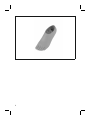
Die Normgelenk-Prothesenfüße 1H38 und 1H40 sind für den Einsatz in Mo
dular-Prothesen und für Prothesen in Schalenbauweise geeignet. Die funk
tionellen Eigenschaften werden durch die Kombination aus einem konturier
tem Kern und Funktionsschaum erreicht.
1.2 Kombinationsmöglichkeiten
Diese Prothesenkomponente ist kompatibel mit dem Ottobock Modularsys
tem. Die Funktionalität mit Komponenten anderer Hersteller, die über kom
patible modulare Verbindungselemente verfügen, wurde nicht getestet.
2 Bestimmungsgemäße Verwendung
2.1 Verwendungszweck
Das Produkt ist ausschließlich für die exoprothetische Versorgung der unte
ren Extremität einzusetzen.
Das Produkt ist für die Geriatrieversorgung geeignet.
2.2 Einsatzgebiet
Unsere Komponenten funktionieren optimal, wenn sie mit geeigneten Kom
ponenten kombiniert werden, ausgewählt auf Basis von Körpergewicht und
Mobilitätsgrad, die mit unserer MOBIS Klassifizierungsinformation identifi
zierbar sind, und die über passende modulare Verbindungselemente verfü
gen.
3

m°
kg
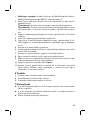
Das Produkt wird für Mobilitätsgrad1 (Innenbereichsgeher)
empfohlen.
Das Produkt darf nur in TF-Prothesen eingesetzt werden.
• Das maximal zugelassene Körpergewicht ist in den Technischen Daten
angegeben (siehe Seite9).
• Die bilaterale Verwendung von 1H* Prothesenfüßen stellt erhöhte Anfor
derungen an die Balance des Benutzers.
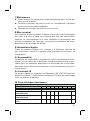
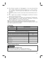
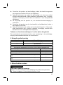
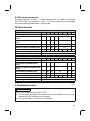
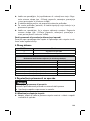
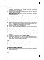
2.3 Umgebungsbedingungen
Zulässige Umgebungsbedingungen
Einsatztemperaturbereich -10 °C bis +60°C
Zulässige relative Luftfeuchtigkeit 0 % bis 90 %, nicht kondensierend
Unzulässige Umgebungsbedingungen
Mechanische Vibrationen oder Stöße
Schweiß, Urin, Süßwasser, Salzwasser, Säuren
Staub, Sand, stark hygroskopische Partikel (z.B. Talkum)
Sonstige Umgebungsbedingungen
UV-Licht nicht beständig
Hydrolyse nicht beständig
2.4 Lebensdauer
Das Produkt wurde vom Hersteller mit 2Millionen Belastungszyklen geprüft.
Dies entspricht, je nach Aktivitätsgrad des Benutzers, einer Lebensdauer
von maximal 3Jahren.
3 Sicherheit
3.1 Bedeutung der Warnsymbolik
VORSICHT Warnung vor möglichen Unfall- und Verletzungsgefahren.
HINWEIS Warnung vor möglichen technischen Schäden.
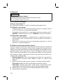
3.2 Allgemeine Sicherheitshinweise
VORSICHT!
Verletzungsgefahr und Gefahr von Produktschäden
4

►Halten Sie das Einsatzgebiet des Produkts ein und setzen Sie es keiner
Überbeanspruchung aus (siehe Seite3).
►Verwenden Sie das Produkt nicht über die geprüfte Lebensdauer hin
aus, um Verletzungsgefahr und Produktschäden zu verhindern.
►Verwenden Sie das Produkt nur für einen Patienten, um Verletzungsge
fahr und Produktschäden zu verhindern.
►Beachten Sie die Kombinationsmöglichkeiten/Kombinationsausschlüsse
in den Gebrauchsanweisungen der Produkte.
HINWEIS!
Gefahr von Produktschäden und Funktionseinschränkungen
►Setzen Sie das Produkt keinen unzulässigen Umgebungsbedingungen
aus.
►Prüfen Sie das Produkt auf Schäden, wenn es unzulässigen Umge
bungsbedingungen ausgesetzt war.
►Verwenden Sie das Produkt nicht, wenn es beschädigt oder in einem
zweifelhaften Zustand ist. Ergreifen Sie geeignete Maßnahmen: (z.B.
Reinigung, Reparatur, Ersatz, Kontrolle durch den Hersteller oder eine
Fachwerkstatt).
►Arbeiten Sie sorgfältig mit dem Produkt um mechanische Beschädigung
zu verhindern.
►Prüfen Sie das Produkt auf Funktion und Gebrauchsfähigkeit, wenn Sie
Schäden vermuten.
►Verwenden Sie das Produkt nicht, wenn seine Funktion eingeschränkt
ist. Ergreifen Sie geeignete Maßnahmen: (z.B. Reinigung, Reparatur,
Ersatz, Kontrolle durch den Hersteller oder eine Fachwerkstatt)
Anzeichen von Funktionsveränderungen oder -verlust beim Gebrauch
Ein verringerter Vorfußwiderstand oder ein verändertes Abrollverhalten sind
spürbare Anzeichen von Funktionsverlust.
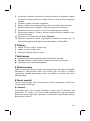
4 Lieferumfang
Menge Benennung
1 Gebrauchsanweisung
1 Prothesenfuß
1H38, 1H40
Ersatzteile/Zubehör (nicht im Lieferumfang)
Benennung Kennzeichen
Einzelteile-Pack für Normgelenk-Füße 2D5
5

1H38, 1H40
Ersatzteile/Zubehör (nicht im Lieferumfang)
Benennung Kennzeichen
Dorsalanschlag-Set 2S88*
Verbindungskappe 2R22*
Normgelenk-Fußadapter mit Verschraubung (Titan) 2R33*
Normgelenk-Fußadapter mit Verschraubung (Aluminium) 2R51*
Normgelenk-Fußadapter mit Verschraubung (Stahl) 2R10*
5 Gebrauchsfähigkeit herstellen
VORSICHT
Fehlerhafter Aufbau oder Montage
Verletzungsgefahr durch Schäden an Prothesenkomponenten
►Beachten Sie die Aufbau- und Montagehinweise.
5.1 Fußadapter montieren
►Den Fußadapter gemäß den Anweisungen seiner Gebrauchsanweisung
am Prothesenfuß montieren.
5.2 Aufbau
HINWEIS
Beschleifen des Prothesenfußes
Vorzeitiger Verschleiß durch Beschädigung des Prothesenfußes
►Beschleifen Sie den Prothesenfuß nicht.
5.2.1 Grundaufbau
Grundaufbau TF
►Die Angaben in der Gebrauchsanweisung des Prothesenkniegelenks
beachten.
5.2.2 Statischer Aufbau
• Ottobock empfiehlt den Aufbau der Prothese mit Hilfe des
L.A.S.A.R.Posture zu kontrollieren und bei Bedarf anzupassen.
• Bei Bedarf können die Aufbauempfehlungen (TF-Modular-Beinprothe
sen: 646F219*, TT-Modular-Beinprothesen: 646F336*) bei Ottobock an
gefordert werden.
6

5.2.3 Dynamische Anprobe
• Den Aufbau der Prothese in der Frontalebene und der Sagittalebene an
passen (z.B. durch Winkeländerung oder Verschiebung), um eine opti
male Schrittabwicklung sicherzustellen.
• Entfernen Sie den Schutz aus Kunststoff nach Abschluss der dynami
schen Anprobe und der Gehübungen vom Justierkern.
5.3 Optional: Schaumstoffüberzug montieren
Der Schaumstoffüberzug sitzt zwischen Prothesenschaft und Prothesenfuß.
Er wird länger zugeschnitten, um die Bewegungen des Prothesenfußes und
des Prothesenkniegelenks ausgleichen zu können. Während der Beugung
des Prothesenkniegelenks wird der Schaumstoffüberzug posterior gestaucht
und anterior gedehnt. Um die Haltbarkeit zu erhöhen, sollte der Schaumstof
füberzug so wenig wie möglich gedehnt werden. Am Prothesenfuß befindet
sich ein Verbindungselement (z.B. Verbindungsplatte, Verbindungskappe,
Anschlusskappe).
>Benötigte Materialien: Entfettender Reiniger (z.B. Isopropylalkohol
634A58), Kontaktkleber 636N9 oder Kunststoffkleber 636W17
1) Die Länge des Schaumstoffüberzugs an der Prothese messen und die
Längenzugabe addieren.
TT-Prothesen: Zugabe distal für die Bewegung des Prothesenfußes.
TF-Prothesen: Zugabe proximal des Kniedrehpunkts für die Beugung
des Prothesenkniegelenks und Zugabe distal für die Bewegung des Pro
thesenfußes.
2) Den Schaumstoffrohling ablängen und im proximalen Bereich am Pro
thesenschaft einpassen.
3) Den Schaumstoffrohling auf die Prothese ziehen.
4) Das Verbindungselement auf die Fußhülle oder den Prothesenfuß set
zen. Je nach Ausführung rastet das Verbindungselement im Rand ein
oder sitzt am Fußadapter.
5) Den Prothesenfuß an der Prothese montieren.
6) Die Außenkontur des Verbindungselements auf der distalen Schnittflä
che des Schaumstoffrohlings anzeichnen.
7) Den Prothesenfuß demontieren und das Verbindungselement entfernen.
8) Das Verbindungselement mit einem entfettenden Reiniger reinigen.
9) Das Verbindungselement gemäß der angezeichneten Außenkontur auf
die distale Schnittfläche des Schaumstoffrohlings kleben.
10) Die Verklebung trocknen lassen (ca. 10Minuten).
7

11) Den Prothesenfuß montieren und die kosmetische Außenform anpassen.
Dabei die Kompression durch Überziehstrümpfe oder SuperSkin be
rücksichtigen.
6 Reinigung
1) Das Produkt mit einem feuchten, weichen Tuch reinigen.
2) Das Produkt mit einem weichen Tuch abtrocknen.
3) Die Restfeuchtigkeit an der Luft trocknen lassen.
7 Wartung
►Die Prothesenkomponenten nach den ersten 30Tagen Gebrauch einer
Inspektion unterziehen.
►Die komplette Prothese während der normalen Konsultation auf Abnut
zung überprüfen.
►Jährliche Sicherheitskontrollen durchführen.
8 Entsorgung
Das Produkt darf nicht überall mit unsortiertem Hausmüll entsorgt werden.
Eine unsachgemäße Entsorgung kann sich schädlich auf die Umwelt und
die Gesundheit auswirken. Beachten Sie die Angaben der zuständigen Be
hörde Ihres Landes zu Rückgabe, Sammel- und Entsorgungsverfahren.
9 Rechtliche Hinweise
Alle rechtlichen Bedingungen unterliegen dem jeweiligen Landesrecht des
Verwenderlandes und können dementsprechend variieren.
9.1 Haftung
Der Hersteller haftet, wenn das Produkt gemäß den Beschreibungen und
Anweisungen in diesem Dokument verwendet wird. Für Schäden, die durch
Nichtbeachtung dieses Dokuments, insbesondere durch unsachgemäße
Verwendung oder unerlaubte Veränderung des Produkts verursacht werden,
haftet der Hersteller nicht.
9.2 CE-Konformität
Das Produkt erfüllt die Anforderungen der Verordnung (EU) 2017/745 über
Medizinprodukte. Die CE-Konformitätserklärung kann auf der Website des
Herstellers heruntergeladen werden.
8

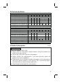
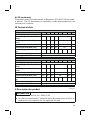
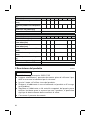
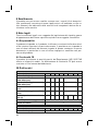
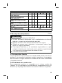
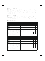
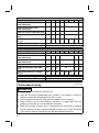
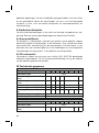
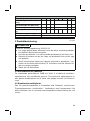
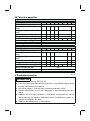
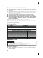
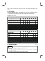
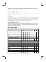
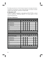
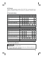
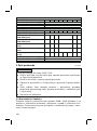
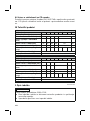
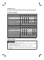
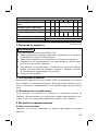
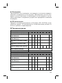
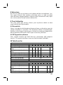
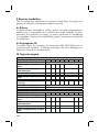
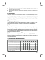
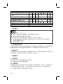
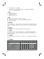
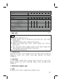
10 Technische Daten
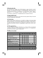
1H38
Größen [cm] 21 22 23 24 25 26 27 28
Absatzhöhe [mm] 10±5
Systemhöhe mit 2R33/2R10 [mm] 42 43 44 45 46 47
Einbauhöhe mit 2R33/2R10 [mm] 60 61 62 63 64
Systemhöhe mit 2R51 [mm] 46 47 48 49 50 51
Einbauhöhe mit 2R51 [mm] 64 65 66 67 68
Produktgewicht ohne Adapter [g] 255 275 305 335 360 365 420 435
Max. Körpergewicht [kg] 100
Mobilitätsgrad 1
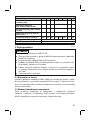
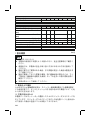
1H40
Größen [cm] 22 23 24 25 26 27 28 29
Absatzhöhe [mm] 25±5
Systemhöhe mit 2R33/2R10 [mm] 43 44 45 46 47 51
Einbauhöhe mit 2R33/2R10 [mm] 61 62 63 64 65 69
Systemhöhe mit 2R51 [mm] 47 48 49 50 51 55
Einbauhöhe mit 2R51 [mm] 65 66 67 68 69 73
Produktgewicht ohne Adapter [g] 295 305 320 370 400 440 470 530
Max. Körpergewicht [kg] 100
Mobilitätsgrad 1
1 Product description English
INFORMATION
Date of last update: 2021-07-02
►Please read this document carefully before using the product and
observe the safety notices.
►Instruct the user in the safe use of the product.
►Please contact the manufacturer if you have questions about the
product or in case of problems.
►Report each serious incident related to the product to the manufacturer
and to the relevant authority in your country. This is particularly import
ant when there is a decline in the health state.
►Please keep this document for your records.
9

1.1 Construction and Function
The 1H38 and 1H40 single axis prosthetic feet are suitable for use in both
modular and exoskeletal prostheses. The functional properties are achieved
through the combination of a contoured core and functional foam.
1.2 Combination possibilities
This prosthetic component is compatible with Ottobock's system of modular
connectors. Functionality with components of other manufacturers that have
compatible modular connectors has not been tested.
2 Intended use
2.1 Indications for use
The product is intended exclusively for lower limb exoprosthetic fittings.
The product is suitable for fittings of geriatric patients.
2.2 Area of application
Our components perform optimally when paired with appropriate compon
ents based upon weight and mobility grades identifiable by our MOBIS clas
sification information and which have appropriate modular connectors.
m°
kg
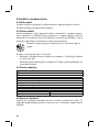
The product is recommended for mobility grade1 (indoor walk
er).
The product must be used in TF prostheses only.
• The maximum approved body weight is specified in the technical data
(see page15).
• The bilateral use of 1H* prosthetic feet imposes stricter requirements for
the user's balance.
2.3 Environmental conditions
Allowable environmental conditions
Temperature range for use: -10°Cto +60°C
Allowable relative humidity 0% to 90%, non-condensing
Unallowable environmental conditions
Mechanical vibrations or impacts
Perspiration, urine, fresh water, salt water, acids
Dust, sand, highly hygroscopic particles (e.g. talcum)
Other environmental conditions
UV light Not resistant
10

Other environmental conditions
Hydrolysis Not resistant
2.4 Lifetime
The product was tested by the manufacturer with 2million load cycles.
Depending on the user’s activity level, this corresponds to a maximum life
time of 3years.
3 Safety
3.1 Explanation of warning symbols
CAUTION Warning regarding possible risks of accident or injury.
NOTICE Warning regarding possible technical damage.
3.2 General safety instructions
CAUTION!
Risk of injury and risk of product damage
►Comply with the product's field of application and do not expose it to
excessive strain (see page10).
►To avoid the risk of injury and product damage, do not use the product
beyond the tested lifetime.
►To avoid the risk of injury and product damage, only use the product for
a single patient.
►Note the combination possibilities/combination exclusions in the instruc
tions for use of the products.
NOTICE!
Risk of product damage and limited functionality
►Do not expose the product to prohibited environmental conditions.
►Check the product for damage if it has been exposed to prohibited envir
onmental conditions.
►Do not use the product if it is damaged or in a questionable condition.
Take suitable measures (e.g.cleaning, repair, replacement, inspection
by the manufacturer or a specialist workshop).
►To prevent mechanical damage, use caution when working with the
product.
11

►If you suspect the product is damaged, check it for proper function and
readiness for use.
►Do not use the product if its functionality is restricted. Take suitable
measures (e.g.cleaning, repair, replacement, inspection by the manu
facturer or a specialist workshop).
Signs of changes in or loss of functionality during use
Decreased forefoot resistance or changes in roll-over behaviour are notice
able indications of loss of functionality.
4 Scope of delivery
Quantity Designation
1 Instructions for use
1 Prosthetic foot
1H38, 1H40
Spare parts/accessories (not included in the scope of delivery)
Designation Reference number
Single component pack for single axis feet 2D5
Dorsal stop set 2S88*
Connection cap 2R22*
Single axis foot adapter with screw connection (titanium) 2R33*
Single axis foot adapter with screw connection (aluminium) 2R51*
Single axis foot adapter with screw connection (steel) 2R10*
5 Preparing the product for use
CAUTION
Incorrect alignment or assembly
Risk of injury due to damaged prosthetic components
►Observe the alignment and assembly instructions.
5.1 Installing the foot adapter
►Install the foot adapter on the prosthetic foot according to its instructions
for use.
5.2 Alignment
NOTICE
Grinding the prosthetic foot
Premature wear resulting from damage to the prosthetic foot
12

►Do not grind the prosthetic foot.
5.2.1 Bench Alignment
TF bench alignment
►Observe the information in the prosthetic knee joint instructions for use.
5.2.2 Static Alignment
• Ottobock recommends checking the alignment of the prosthesis using
the L.A.S.A.R.Posture and adapting it as needed.
• If necessary, the alignment recommendations (TF modular leg pros
theses: 646F219*, TT modular leg prostheses: 646F336*) may be
requested from Ottobock.
5.2.3 Dynamic Trial Fitting
• Adapt the alignment of the prosthesis in the frontal plane and the sagittal
plane (e.g.by making angle or slide adjustments) to ensure an optimum
gait pattern.
• Remove the plastic protector from the pyramid after completing the
dynamic fitting and the walking exercises.
5.3 Optional: Installing the foam cover
The foam cover sits between the prosthetic socket and prosthetic foot. It is
cut longer in order to compensate for the movements of the prosthetic foot
and prosthetic knee joint. During flexion of the prosthetic knee joint, the foam
cover undergoes posterior compression and anterior elongation. The foam
cover should be stretched as little as possible in order to increase its service
life. There is a connecting element (such asa connection plate, connection
cap or connection cover) on the prosthetic foot.
>Required materials: degreasing cleaner (e.g.634A58 isopropyl alco
hol), 636N9 contact adhesive or 636W17 plastic adhesive
1) Measure the length of the foam cover on the prosthesis and add the
length allowance.
TT prostheses: Distal allowance for movement of the prosthetic foot.
TF prostheses: Allowance proximal of the knee rotation point for flexion
of the prosthetic knee joint and distal allowance for movement of the
prosthetic foot.
2) Cut the pre-shaped foam cover to length and fit it in the proximal area on
the prosthetic socket.
3) Pull the foam cover over the prosthesis.
4) Set the connecting element onto the footshell or prosthetic foot. Depend
ing on the version, the connecting element engages in the edge or rests
on the foot adapter.
13

5) Install the prosthetic foot on the prosthesis.
6) Mark the outer contour of the connecting element on the distal face of
the foam cover.
7) Disassemble the prosthetic foot and remove the connecting element.
8) Clean the connecting element using a degreasing cleaner.
9) Glue the connecting element onto the distal face of the foam cover
according to the marked outer contour.
10) Let the glue dry (approx. 10minutes).
11) Install the prosthetic foot and adapt the exterior cosmetic shape. Take
into account compression caused by cosmetic stockings or SuperSkin.
6 Cleaning
1) Clean the product with a damp, soft cloth.
2) Dry the product with a soft cloth.
3) Allow to air dry in order to remove residual moisture.
7 Maintenance
►The prosthetic components should be inspected after the first 30 days of
use.
►Inspect the entire prosthesis for wear during normal consultations.
►Conduct annual safety inspections.
8 Disposal
In some jurisdictions it is not permissible to dispose of the product with
unsorted household waste. Improper disposal can be harmful to health and
the environment. Observe the information provided by the responsible
authorities in your country regarding return, collection and disposal proced
ures.
9 Legal information
All legal conditions are subject to the respective national laws of the country
of use and may vary accordingly.
9.1 Liability
The manufacturer will only assume liability if the product is used in accord
ance with the descriptions and instructions provided in this document. The
manufacturer will not assume liability for damage caused by disregarding the
information in this document, particularly due to improper use or unauthor
ised modification of the product.
14

9.2 CE conformity
The product meets the requirements of Regulation (EU) 2017/745 on medic
al devices. The CE declaration of conformity can be downloaded from the
manufacturer's website.
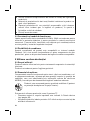
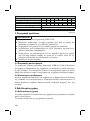
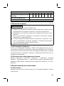
10 Technical data
1H38
Sizes [cm] 21 22 23 24 25 26 27 28
Heel height [mm] 10±5
System height with 2R33/2R10
[mm]
42 43 44 45 46 47
Build height with 2R33/2R10
[mm]
60 61 62 63 64
System height with 2R51 [mm] 46 47 48 49 50 51
Build height with 2R51 [mm] 64 65 66 67 68
Product weight without adapter
[g]
255 275 305 335 360 365 420 435
Max. body weight [kg] 100
Mobility grade 1
1H40
Sizes [cm] 22 23 24 25 26 27 28 29
Heel height [mm] 25±5
System height with 2R33/2R10
[mm]
43 44 45 46 47 51
Build height with 2R33/2R10
[mm]
61 62 63 64 65 69
System height with 2R51 [mm] 47 48 49 50 51 55
Build height with 2R51 [mm] 65 66 67 68 69 73
Product weight without adapter
[g]
295 305 320 370 400 440 470 530
Max. body weight [kg] 100
Mobility grade 1
1 Description du produit Français
INFORMATION
Date de la dernière mise à jour: 2021-07-02
►Veuillez lire attentivement l’intégralité de ce document avant d’utiliser le
produit ainsi que respecter les consignes de sécurité.
15

►Apprenez à l’utilisateur comment utiliser son produit en toute sécurité.
►Adressez-vous au fabricant si vous avez des questions concernant le
produit ou en cas de problèmes.
►Signalez tout incident grave survenu en rapport avec le produit, notam
ment une aggravation de l’état de santé, au fabricant et à l’autorité
compétente de votre pays.
►Conservez ce document.
1.1 Conception et fonctionnement
Les pieds prothétiques à articulation normalisée 1H38 et 1H40 sont conçus
pour être utilisés avec des prothèses modulaires et des prothèses exosque
lettiques. Les propriétés fonctionnelles sont obtenues au moyen de
l’association d’un noyau modelé et d’une mousse fonctionnelle.
1.2 Combinaisons possibles
Ce composant prothétique est compatible avec le système modulaire
Ottobock. Le fonctionnement avec des composants d’autres fabricants dis
posant de connecteurs modulaires compatibles n’a pas été testé.
2 Utilisation conforme
2.1 Usage prévu
Le produit est exclusivement destiné à l’appareillage exoprothétique des
membres inférieurs.
Le produit est adapté à un appareillage gériatrique.
2.2 Domaine d’application
Le fonctionnement de nos composants est optimal lorsqu’ils sont associés à
des composants appropriés, sélectionnés selon le poids de l’utilisateur et le
niveau de mobilité, identifiables à l’aide de notre information sur la classifi
cation MOBIS et disposant de connecteurs modulaires adaptés.
m°
kg
Le produit est recommandé pour le niveau de mobilité1 (mar
cheur en intérieur).
L’utilisation de ce produit est autorisée uniquement dans des prothèses
transfémorales (TF).
• Le poids corporel maximum admissible est indiqué dans le chapitre
consacré aux caractéristiques techniques (consulter la page21).
• Une utilisation bilatérale des pieds prothétiques 1H* imposent des exi
gences accrues quant à l’équilibre de l’utilisateur.
16

2.3 Conditions d’environnement
Conditions d’environnement autorisées
Plage de température de fonctionnement -10°Cà+60°C
Humidité relative de l’air admise 0%à90%, sans condensation
Conditions d’environnement non autorisées
Vibrations mécaniques ou chocs
Sueur, urine, eau douce, eau salée, acides
Poussières, grains de sable, particules hygroscopiques (talc par ex.)
Autres conditions d’environnement
Rayons UV Non résistant
Hydrolyse Non résistant
2.4 Durée de vie
Le fabricant a contrôlé le produit en le soumettant à 2millions de cycles de
charge. Ceci correspond, en fonction du degré d’activité de l'utilisateur, à
une durée de vie maximale de 3ans.
3 Sécurité
3.1 Signification des symboles de mise en garde
PRUDENCE Mise en garde contre les éventuels risques d’accidents
et de blessures.
AVIS Mise en garde contre les éventuels dommages tech
niques.
3.2 Consignes générales de sécurité
PRUDENCE!
Risque de blessure et risque de détérioration du produit
►Respecter le domaine d’application du produit et ne pas l’exposer à une
sollicitation excessive (consulter la page16).
►N’utilisez pas le produit au-delà de la durée de vie testée pour prévenir
tout risque de blessure et toute détérioration du produit.
►Utilisez le produit uniquement pour un patient pour prévenir tout risque
de blessure et toute détérioration du produit.
►Respecter les combinaisons possibles/exclues qui sont indiquées dans
les notices d’utilisation des produits.
17

AVIS!
Risque de détériorations du produit et de restrictions fonctionnelles
►Ne pas exposer le produit à des conditions ambiantes non autorisées.
►En cas d’exposition à des conditions ambiantes non autorisées, vérifier
que le produit n’a subi aucun dommage.
►Ne pas utiliser le produit s’il est endommagé ou en cas de doute sur son
état. Prendre les mesures nécessaires (p.ex. nettoyage, réparation,
remplacement, contrôle par le fabricant ou un atelier spécialisé).
►Manipuler le produit avec précaution pour éviter toute dommage méca
nique.
►En cas de doute sur l’état du produit, vérifier qu’il est bien en état de
fonctionner.
►Ne pas utiliser le produit si sa fonctionnalité est limitée. Prendre les me
sures nécessaires (p.ex. nettoyage, réparation, remplacement, contrôle
par le fabricant ou un atelier spécialisé).
Signes de modification ou de perte de fonctionnalité détectés lors de
l’utilisation
Une réduction de la résistance de l’avant-pied ou un comportement modifié
du déroulement sont des signes perceptibles vous alertant d’une perte de
fonctionnalité.
4 Contenu de la livraison
Quantité Désignation
1 Instructions d’utilisation
1 Pied prothétique
1H38, 1H40
Pièces de rechange/accessoires (non compris dans la livraison)
Désignation Référence
Kit de pièces détachées pour pieds à articulation normali
sée
2D5
Kit de butées dorsales 2S88*
Plaque d’attache 2R22*
Adaptateur de pied à articulation normalisée avec fixation
(titane)
2R33*
Adaptateur de pied à articulation normalisée avec fixation
(aluminium)
2R51*
Adaptateur de pied à articulation normalisée avec fixation
(acier)
2R10*
18

5 Mise en service du produit
PRUDENCE
Alignement ou montage incorrect
Risque de blessure occasionnée par des composants prothétiques endom
magés
►Respectez les consignes relatives à l’alignement et au montage.
5.1 Montage de l’adaptateur de pied
►Montez l’adaptateur de pied sur le pied prothétique selon les consignes
des instructions d’utilisation de l’adaptateur.
5.2 Alignement
AVIS
Ponçage du pied prothétique
Usure précoce due à une dégradation du pied prothétique
►Ne poncez pas le pied prothétique.
5.2.1 Alignement de base
Alignement de base TF
►Respecter les indications figurant dans les instructions d’utilisation de
l’articulation de genou prothétique.
5.2.2 Alignement statique
• Ottobock recommande de contrôler l’alignement de la prothèse avec le
L.A.S.A.R.Posture et, si besoin, d’ajuster cet alignement.
• En cas de besoin, Ottobock vous fournira les recommandations
d’alignement (prothèses de jambe TF modulaires: 646F219*, prothèses
de jambe TT modulaires: 646F336*).
5.2.3 Essai dynamique
• Ajustez l’alignement de la prothèse dans le plan frontal et le plan sagittal
(p.ex. modification de l’angle ou décalage) afin d’assurer un déroule
ment optimal du pas.
• Retirez la protection en plastique de la pyramide une fois l’essayage dy
namique terminé et après les exercices d’entraînement à la marche.
5.3 Facultatif: pose du revêtement en mousse
Le revêtement en mousse est logé entre l’emboîture de prothèse et le pied
prothétique. Il est découpé en laissant une marge pour pouvoir compenser
les mouvements du pied prothétique et de l’articulation de genou prothé
19

tique. Pendant la flexion de l’articulation de genou prothétique, le revête
ment en mousse est écrasé dans sa partie arrière et distendu dans sa partie
avant. Pour augmenter la durée d’utilisation du revêtement en mousse, il est
conseillé de le soumettre le moins possible aux distensions. Le pied prothé
tique comporte un élément de raccordement (parex. une plaque de raccor
dement, un protège-connexion ou une plaque d’attache).
>Matériaux requis : dégraissant (parex. alcool d’isopropyle 634A58),
colle de contact 636N9 ou colle synthétique 636W17
1) Mesurer la prothèse et y ajouter une marge pour déterminer la longueur
du revêtement en mousse.
Prothèses TT : prévoir de la marge côté distal pour le mouvement du
pied prothétique.
Prothèses TF : prévoir de la marge côté proximal par rapport au centre
de rotation du genou pour la flexion de l’articulation de genou prothé
tique et de la marge côté distal pour le mouvement du pied prothétique.
2) Découpez la longueur de mousse requise et mettez-la en place dans la
zone proximale de l’emboîture de prothèse.
3) Placez la mousse sur la prothèse.
4) Placez l’élément de raccordement sur l’enveloppe de pied ou sur le pied
prothétique. En fonction du modèle, l’élément de raccordement
s’enclenche dans le bord ou est posé sur l’adaptateur de pied.
5) Assemblez le pied prothétique avec la prothèse.
6) Tracez le contour extérieur de l’élément de raccordement sur la surface
de coupe distale de la mousse.
7) Démontez le pied prothétique et retirez l’élément de raccordement.
8) Nettoyez l’élément de raccordement à l’aide d’un dégraissant.
9) Collez l’élément de raccordement sur la surface de coupe distale de la
mousse en fonction du tracé du contour extérieur.
10) Laissez la colle sécher (env. 10minutes).
11) Montez le pied prothétique et adaptez le revêtement esthétique externe.
Tenez compte de la compression de la mousse exercée par des bas cos
métiques ou SuperSkin.
6 Nettoyage
1) Nettoyez le produit à l’aide d’un chiffon doux humide.
2) Séchez le produit à l’aide d’un chiffon doux.
3) Laissez sécher l’humidité résiduelle à l’air.
20
Sayfa yükleniyor...
Sayfa yükleniyor...
Sayfa yükleniyor...
Sayfa yükleniyor...
Sayfa yükleniyor...
Sayfa yükleniyor...
Sayfa yükleniyor...
Sayfa yükleniyor...
Sayfa yükleniyor...
Sayfa yükleniyor...
Sayfa yükleniyor...
Sayfa yükleniyor...
Sayfa yükleniyor...
Sayfa yükleniyor...
Sayfa yükleniyor...
Sayfa yükleniyor...
Sayfa yükleniyor...
Sayfa yükleniyor...
Sayfa yükleniyor...
Sayfa yükleniyor...
Sayfa yükleniyor...
Sayfa yükleniyor...
Sayfa yükleniyor...
Sayfa yükleniyor...
Sayfa yükleniyor...
Sayfa yükleniyor...
Sayfa yükleniyor...
Sayfa yükleniyor...
Sayfa yükleniyor...
Sayfa yükleniyor...
Sayfa yükleniyor...
Sayfa yükleniyor...
Sayfa yükleniyor...
Sayfa yükleniyor...
Sayfa yükleniyor...
Sayfa yükleniyor...
Sayfa yükleniyor...
Sayfa yükleniyor...
Sayfa yükleniyor...
Sayfa yükleniyor...
Sayfa yükleniyor...
Sayfa yükleniyor...
Sayfa yükleniyor...
Sayfa yükleniyor...
Sayfa yükleniyor...
Sayfa yükleniyor...
Sayfa yükleniyor...
Sayfa yükleniyor...
Sayfa yükleniyor...
Sayfa yükleniyor...
Sayfa yükleniyor...
Sayfa yükleniyor...
Sayfa yükleniyor...
Sayfa yükleniyor...
Sayfa yükleniyor...
Sayfa yükleniyor...
Sayfa yükleniyor...
Sayfa yükleniyor...
Sayfa yükleniyor...
Sayfa yükleniyor...
Sayfa yükleniyor...
Sayfa yükleniyor...
Sayfa yükleniyor...
Sayfa yükleniyor...
Sayfa yükleniyor...
Sayfa yükleniyor...
Sayfa yükleniyor...
Sayfa yükleniyor...
Sayfa yükleniyor...
Sayfa yükleniyor...
Sayfa yükleniyor...
Sayfa yükleniyor...
Sayfa yükleniyor...
Sayfa yükleniyor...
Sayfa yükleniyor...
Sayfa yükleniyor...
Sayfa yükleniyor...
Sayfa yükleniyor...
Sayfa yükleniyor...
Sayfa yükleniyor...
Sayfa yükleniyor...
Sayfa yükleniyor...
Sayfa yükleniyor...
Sayfa yükleniyor...
Sayfa yükleniyor...
Sayfa yükleniyor...
Sayfa yükleniyor...
Sayfa yükleniyor...
Sayfa yükleniyor...
Sayfa yükleniyor...
Sayfa yükleniyor...
Sayfa yükleniyor...
Sayfa yükleniyor...
Sayfa yükleniyor...
Sayfa yükleniyor...
Sayfa yükleniyor...
Sayfa yükleniyor...
Sayfa yükleniyor...
Sayfa yükleniyor...
Sayfa yükleniyor...
Sayfa yükleniyor...
Sayfa yükleniyor...
Sayfa yükleniyor...
Sayfa yükleniyor...
Sayfa yükleniyor...
Sayfa yükleniyor...
Sayfa yükleniyor...
Sayfa yükleniyor...
Sayfa yükleniyor...
Sayfa yükleniyor...
Sayfa yükleniyor...
Sayfa yükleniyor...
Sayfa yükleniyor...
Sayfa yükleniyor...
Sayfa yükleniyor...
Sayfa yükleniyor...
Sayfa yükleniyor...
Sayfa yükleniyor...
Sayfa yükleniyor...
Sayfa yükleniyor...
Sayfa yükleniyor...
Sayfa yükleniyor...
Sayfa yükleniyor...
Sayfa yükleniyor...
Sayfa yükleniyor...
Sayfa yükleniyor...
Sayfa yükleniyor...
Sayfa yükleniyor...
Sayfa yükleniyor...
Sayfa yükleniyor...
Sayfa yükleniyor...
Sayfa yükleniyor...
Sayfa yükleniyor...
Sayfa yükleniyor...
Sayfa yükleniyor...
Sayfa yükleniyor...
Sayfa yükleniyor...
Sayfa yükleniyor...
Sayfa yükleniyor...
Sayfa yükleniyor...
Sayfa yükleniyor...
Sayfa yükleniyor...
Sayfa yükleniyor...
Sayfa yükleniyor...
-
 1
1
-
 2
2
-
 3
3
-
 4
4
-
 5
5
-
 6
6
-
 7
7
-
 8
8
-
 9
9
-
 10
10
-
 11
11
-
 12
12
-
 13
13
-
 14
14
-
 15
15
-
 16
16
-
 17
17
-
 18
18
-
 19
19
-
 20
20
-
 21
21
-
 22
22
-
 23
23
-
 24
24
-
 25
25
-
 26
26
-
 27
27
-
 28
28
-
 29
29
-
 30
30
-
 31
31
-
 32
32
-
 33
33
-
 34
34
-
 35
35
-
 36
36
-
 37
37
-
 38
38
-
 39
39
-
 40
40
-
 41
41
-
 42
42
-
 43
43
-
 44
44
-
 45
45
-
 46
46
-
 47
47
-
 48
48
-
 49
49
-
 50
50
-
 51
51
-
 52
52
-
 53
53
-
 54
54
-
 55
55
-
 56
56
-
 57
57
-
 58
58
-
 59
59
-
 60
60
-
 61
61
-
 62
62
-
 63
63
-
 64
64
-
 65
65
-
 66
66
-
 67
67
-
 68
68
-
 69
69
-
 70
70
-
 71
71
-
 72
72
-
 73
73
-
 74
74
-
 75
75
-
 76
76
-
 77
77
-
 78
78
-
 79
79
-
 80
80
-
 81
81
-
 82
82
-
 83
83
-
 84
84
-
 85
85
-
 86
86
-
 87
87
-
 88
88
-
 89
89
-
 90
90
-
 91
91
-
 92
92
-
 93
93
-
 94
94
-
 95
95
-
 96
96
-
 97
97
-
 98
98
-
 99
99
-
 100
100
-
 101
101
-
 102
102
-
 103
103
-
 104
104
-
 105
105
-
 106
106
-
 107
107
-
 108
108
-
 109
109
-
 110
110
-
 111
111
-
 112
112
-
 113
113
-
 114
114
-
 115
115
-
 116
116
-
 117
117
-
 118
118
-
 119
119
-
 120
120
-
 121
121
-
 122
122
-
 123
123
-
 124
124
-
 125
125
-
 126
126
-
 127
127
-
 128
128
-
 129
129
-
 130
130
-
 131
131
-
 132
132
-
 133
133
-
 134
134
-
 135
135
-
 136
136
-
 137
137
-
 138
138
-
 139
139
-
 140
140
-
 141
141
-
 142
142
-
 143
143
-
 144
144
-
 145
145
-
 146
146
-
 147
147
-
 148
148
-
 149
149
-
 150
150
-
 151
151
-
 152
152
-
 153
153
-
 154
154
-
 155
155
-
 156
156
-
 157
157
-
 158
158
-
 159
159
-
 160
160
-
 161
161
-
 162
162
-
 163
163
-
 164
164


diğer dillerde
- slovenčina: Ottobock 1H38 Používateľská príručka
- română: Ottobock 1H38 Manual de utilizare
İlgili makaleler
-
Ottobock 3S124 Kullanım kılavuzu
-
Ottobock 3R80 Kullanım kılavuzu
-
-
Ottobock 3R93 Kullanım kılavuzu
-
Ottobock 2R40 Kullanım kılavuzu
-
Ottobock 7E8 Kullanma talimatları
-
Ottobock 2R54-M10 Kullanım kılavuzu
-
-
Ottobock 7E10 Kullanma talimatları
-
Ottobock 4R84 Double Adapter Pyramid Kullanma talimatları