
YAMAHA ELECTRONICS CORPORATION, USA 6660 ORANGETHORPE AVE., BUENA PARK, CALIF. 90620, U.S.A.
YAMAHA CANADA MUSIC LTD. 135 MILNER AVE., SCARBOROUGH, ONTARIO M1S 3R1, CANADA
YAMAHA ELECTRONIK EUROPA G.m.b.H. SIEMENSSTR. 22-34, 25462 RELLINGEN BEI HAMBURG, F.R. OF GERMANY
YAMAHA ELECTRONIQUE FRANCE S.A. RUE AMBROISE CROIZAT BP70 CROISSY-BEAUBOURG 77312 MARNE-LA-VALLEE CEDEX02, FRANCE
YAMAHA ELECTRONICS (UK) LTD. YAMAHA HOUSE, 200 RICKMANSWORTH ROAD WATFORD, HERTS WD18 7GQ, ENGLAND
YAMAHA SCANDINAVIA A.B. J A WETTERGRENS GATA 1, BOX 30053, 400 43 VÄSTRA FRÖLUNDA, SWEDEN
YAMAHA MUSIC AUSTRALIA PTY, LTD. 17-33 MARKET ST., SOUTH MELBOURNE, 3205 VIC., AUSTRALIA
This document is printed on chlorine free (ECF) paper with soy ink.
2003 All Rights Reserved.
C
GB
Printed in Japan WC01630
000MX-D1_GB_H1-4.fm Page 1 Monday, October 20, 2003 5:21 PM

• To assure the finest performance, please read this manual carefully.
Keep it in a safe place for future reference.
• Install this unit in a well ventilated, cool, dry, clean place – away from
direct sunlight, heat sources, vibration, dust, moisture, and/or cold.
Allow ventilation space of at least 30 cm on the top, 10 cm on the left
and right, and 10 cm on the back of this unit.
• Locate this unit away from other electrical appliances, motors, or
transformers to avoid humming sounds.
• Do not expose this unit to sudden temperature changes from cold to hot,
and do not locate this unit in a environment with high humidity (i.e. a
room with a humidifier) to prevent condensation inside this unit, which
may cause an electrical shock, fire, damage to this unit, and/or personal
injury.
• Avoid installing this unit where foreign object may fall onto this unit
and/or this unit may be exposed to liquid dripping or splashing. On the
top of this unit, do not place:
• Other components, as they may cause damage and/or discoloration
on the surface of this unit.
• Burning objects (i.e. candles), as they may cause fire, damage to this
unit, and/or personal injury.
• Containers with liquid in them, as they may fall and liquid may cause
electrical shock to the user and/or damage to this unit.
• Do not cover the top panel of this unit with a newspaper, tablecloth,
curtain, etc. in order not to obstruct heat radiation. If the temperature
inside this unit rises, it may cause fire, damage to this unit, and/or
personal injury.
• Do not plug in this unit to a wall outlet until all connections are
complete.
• Do not operate this unit upside-down. It may overheat, possibly causing
damage.
• Do not use force on switches, knobs and/or cords.
• When disconnecting the power cord from the wall outlet, grasp the
plug; do not pull the cord.
• Do not clean this unit with chemical solvents; this might damage the
finish. Use a clean, dry cloth.
• Only voltage specified on this unit must be used. Using this unit with a
higher voltage than specified is dangerous and may cause fire, damage
to this unit, and/or personal injury. YAMAHA will not be held
responsible for any damage resulting from use of this unit with a
voltage other than specified.
• To prevent damage by lightning, disconnect the power cord from the
wall outlet during an electrical storm.
• Do not attempt to modify or fix this unit. Contact qualified YAMAHA
service personnel when any service is needed. The cabinet should never
be opened for any reasons.
• When not planning to use this unit for long periods of time (i.e.
vacation), disconnect the AC power plug from the wall outlet.
• Be sure to read the “TROUBLESHOOTING” section on common
operating errors before contacting the YAMAHA dealer.
• Before moving this unit, press the STANDBY/ON switch to turn off
this unit, and disconnect the AC power plug from the wall outlet.
SPECIAL INSTRUCTIONS FOR U.K. MODEL
For U.K. customers
If the socket outlets in the home are not suitable for the plug supplied with
this appliance, it should be cut off and an appropriate 3 pin plug fitted. For
details, refer to the instructions described above.
Note: The plug severed from the mains lead must be destroyed, as a plug
with bared flexible cord is hazardous if engaged in a live socket outlet.
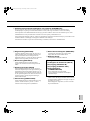
This unit is not disconnected from the AC power source as long as it
is connected to the wall outlet, even if this unit itself is turned off. This
state is called standby mode. In this state, this unit is designed to
consume a very small quantity of power.
WARNING
TO REDUCE THE RISK OF FIRE OR ELECTRIC SHOCK, DO
NOT EXPOSE THIS UNIT TO RAIN OR MOISTURE.
IMPORTANT
The wires in this mains lead are coloured in accordance with the
following code:
GREEN-and-YELLOW: Earth
BLUE: Neutral
BROWN: Live
As the colours of the wires in the mains lead of this apparatus may not
correspond with the coloured markings identifying the terminals in
your plug proceed as follows: The wire which is coloured GREEN-
and-YELLOW must be connected to the terminal in the plug which is
marked by the letter E or by the safety earth symbol or coloured
GREEN or GREEN-and -YELLOW. The wire which is coloured
BLUE must be connected to the terminal which is marked with the
letter N or coloured BLACK. The wire which is coloured BROWN
must be connected to the terminal which is marked with the letter L or
coloured RED.
For Canadian Customers
To prevent electric shock, match wide blade of plug to wide slot and
fully insert.
This Class B digital apparatus complies with Canadian ICES-003.
CAUTION: READ THIS BEFORE OPERATING THIS UNIT TECHNISCHE GEGEVENS
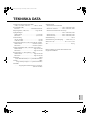
Minimum RMS uitgangsvermogen
(1 kHz, 1,0 % THV, 4 tot 8 Ω)............... 500 W + 500 W
Dynamisch vermogen (IHF)
2/4/6/8 Ω ......................................1000/1000/850/700 W
Dempingsfactor (1 kHz, 8 Ω)meer dan 200
Ingangsgevoeligheid
UNBALANCE.............................................1,3 V/25 kΩ
BALANCE ..................................................2,2 V/10 kΩ
Frequentierespons
1 Hz tot 100 kHz................................................ ± 3,0 dB
10 Hz tot 20 kHz................................................ ± 0,5 dB
Totale harmonische vervorming (1 kHz, 10 W/8
Ω
, LPF: 20 kHz)
UNBALANCE................................ minder dan 0,002 %
BALANCE ..................................... minder dan 0,002 %
Signaal-ruis verhouding (IHF-A Netwerk, LPF: 20 kHz)
UNBALANCE..................................... meer dan 120 dB
BALANCE .......................................... meer dan 120 dB
Kanaalscheiding (5,1 kΩ afgesloten, 1 kHz)
UNBALANCE..................................... meer dan 100 dB
BALANCE .......................................... meer dan 100 dB
Modulatie ....................... PWM (Pulse Width Modulation)
Uitgang.............................SEPP (Single-Ended Push-Pull)
Voeding .................. Resonantie-type schakelende voeding
(frequentie: 88 kHz)
Stroomvoorziening
Modellen voor de VS en Canada
............................................. 120 V wisselstroom, 60 Hz
Model voor Australië........... 240 V wisselstroom, 50 Hz
Modellen voor Groot-Brittannië en Continentaal Europa
............................................. 230 V wisselstroom, 50 Hz
Model voor China ................ 220 V wisselstroom, 50 Hz
Model voor Korea................ 220 V wisselstroom, 60 Hz
Stroomverbruik......................................................... 350 W
Stroomverbruik tijdens standby .............minder dan 0,1 W
Afmetingen (B x H x D).......................435 x 75 x 437 mm
Gewicht ...................................................................10,4 kg
Wijzigingen in technische gegevens voorbehouden.
9
Nederlands
000MX-D1_GB_H2-3.fm Page 1 Monday, October 20, 2003 5:14 PM

1
English
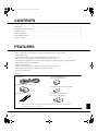
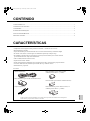
CONTENTS
FEATURES................................................................................................................................................................................ 1
CONTROLS AND FUNCTIONS ............................................................................................................................................. 2
CONNECTIONS ....................................................................................................................................................................... 4
BLOCK DIAGRAMS................................................................................................................................................................ 6
TROUBLESHOOTING............................................................................................................................................................. 8
SPECIFICATIONS ................................................................................................................................................................... 9
• 500 W + 500 W max. (4 to 8 Ω) high-power, high-performance digital stereo power amplifier
• 120 dB dynamic range
• Yamaha-designed LSI chips used in the digital-modulation and power-drive circuits
• Active Power Control System ensures optimum performance under any load
• Constant Gain PLL Modulator provides a fixed open-loop gain that is unaffected by supply voltage fluctuations
• 0.003% THD (Total Harmonic Distortion)
• 100 dB channel separation
• Yamaha’s own high-efficiency, low-noise resonant-type switching power supply
• WBT (German) connectors used for inputs (RCA) and speaker outputs
• Futuristic, super-thin design
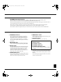
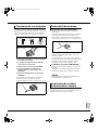
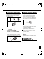
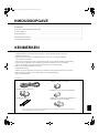
Accessories
Power cable
Clamp filter (for power cable) x 2
Fixing tie x 2
Clamp filter (for audio pin cable)
(U.S.A. and Canada models)
Clamp filter (for RS-232C interface cable)
Clamp filter (for control cable) x 2
(U.S.A. and Canada models)
Be sure to attach the clamp filters to the corresponding cables in order to reduce the electromagnetic interference.
Open the cover and fit the core onto the cables.
FEATURES
01-MX-D1_GB_E.fm Page 1 Wednesday, October 22, 2003 2:05 PM

2
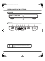
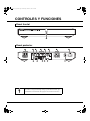
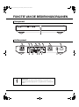
CONTROLS AND FUNCTIONS
Rear Panel
Front Panel
This mark indicates a dangerous electrically live terminal.
To reduce the risk of shock or fire and prevent short circuits, strictly follow
the instructions on page 5 when connecting speakers.
01-MX-D1_GB_E.fm Page 2 Wednesday, October 22, 2003 2:05 PM

3
English
1 STANDBY/ON switch/indicator
This switch is used to set the MX-D1 to on or standby. A small amount of power is used in standby mode.
When the MX-D1 is turned on, this indicator lights blue and the MX-D1 is ready for use.
When the internal temperature rises, this indicator lights blue and purple alternately. If this happen, relocate this unit in a
well ventilated place and turn down the volume of the pre-amplifier etc.
When a fault is detected, the MX-D1’s protection system activates and this indicator lights red. If this happens,
set the MX-D1 to standby mode immediately and disconnect the AC power cable from the AC outlet.
If the indicator continues to light red when you re-connect the AC power cable, contact the nearest Yamaha dealer.
2 SPEAKER terminals
These terminals are for connecting your speakers.
They provide a reliable connection even with really
thick cables. Be sure to connect the left and right
channels, and the speaker polarities (+/-) correctly.
You can connect speakers with impedance of between
4 to 8 ohms.
3 BALANCE jacks
If your source component has balanced XLR output
jacks, connect them to these jacks using XLR cables.
4 MUTE button
You can temporarily mute the output from the MX-D1
by holding down this button. If you need to change
any input connections while the MX-D1 is still on,
hold down this button while you do it. This will
protect your speakers against possible damage due to
sudden loud noises, thumps, and clicks.
5 UNBALANCE jacks
If your source component has unbalanced RCA jacks
(labeled “AUDIO OUTPUT” on the YPC-1), connect
them to these jacks using an audio pin cable.
6 UNBAL/BAL switch
With this switch you can select the BALANCE jacks
or the UNBALANCE jacks.
7 AC IN connector
Connect the supplied AC power cable here.
e POWER switch
(Australia, U.K., Europe, China and Korea models)
Normally, set this switch to the ON position to use the
MX-D1.
To cut off the power supply from the AC line, set this
switch to the OFF position.
8 RS-232C terminal
9 AMP ID switch
0 CONTROL IN jack
q CONTROL OUT jack
w POWER/THROUGH switch
These are for control expansion. Consult your dealer
for details.
01-MX-D1_GB_E.fm Page 3 Wednesday, October 22, 2003 2:05 PM

4
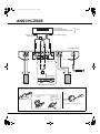
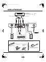
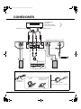
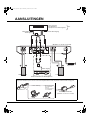
CONNECTIONS
• Pre-amplifier
• PA equipment etc.
• CD player with a volume control
Balanced XLR output
To AC outlet
Speaker (R)
Speaker (L)
Audio
output
Unbalanced RCA output
(U.S.A. and Canada models)
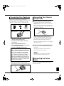
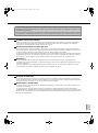
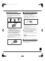
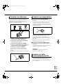
When connecting the YPC-1
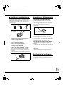
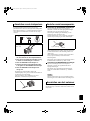
Be sure to attach the clamp filters to the power cable and the audio pin cable as illustrated below.
1. Close the cover. 2. Fix the cable and
the clamp filter by
tightening the fixing
tie.
Power cable
Audio pin cable
(U.S.A. and Canada models)
01-MX-D1_GB_E.fm Page 4 Wednesday, October 22, 2003 3:28 PM

5
English
Speaker cables typically consist of two insulated
conductors. To ensure that the speakers are connected with
the correct polarity (+/-), the insulation on one of the
conductors is a different color or is marked with a line.
1. Strip about 15 mm (5/8”) of insulation from
the ends of the speaker cables.
2. Twist the bare wires tightly to prevent a
short circuit.
3. Unscrew the SPEAKER terminals.
4. Insert the twisted bare wires into the holes
on the SPEAKER terminals.
5. Screw the SPEAKER terminals tight.
When using banana plugs, tighten the terminal knob
and insert the plug into the end of the terminal.
(With the exception of U.K., Europe and Korea models)
Connecting to the BALANCE jacks
Connect your component with the balanced XLR
output jacks.
The pin assignments for these jacks are shown below.
Refer to the owner’s manual of your component and
verify that its output jacks are compatible with the pin
assignments for these jacks.
When connecting, match the pins and insert the
connector of the XLR cable until you hear a “click.”
When disconnecting, pull out the XLR cable while
holding down the lever of the BALANCE jack.
When using this balanced connection, set the UNBAL/
BAL switch to “BAL.”
Connecting to the UNBALANCE jacks
Connect your component with the unbalanced RCA
output jacks.
When using this unbalanced connection, set the
UNBAL/BAL switch to “UNBAL.”
Do not connect your components to both of the
BALANCE jacks and UNBALANCE jacks.
Plug the power cable into the AC IN connector when all
connections are complete, and then plug in the power
cable to the AC outlet.
Caution
When inserting the stripped ends of the speaker
wires as shown above, make sure at least 1/16
inch (1.6 mm) of insulation is inside the wire
holders (i.e no exposed wire is visible) and no
loose conductor wire strands are protruding
after connection. If wires touch each other or
they touch the metal parts of this unit, this unit
and/or speakers could be damaged. To prevent
speaker wire from coming loose, make sure wire
holder are firmly screwed in.
Connecting Your Speakers
15mm
1
2
4
33
5
Red: + (positive)
White: - (negative)
Banana plug
Connecting Your Source
Components
2: hot
1: ground
3: cold
Caution
Connecting the Power
Cable
01-MX-D1_GB_E.fm Page 5 Wednesday, October 22, 2003 2:05 PM

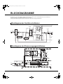
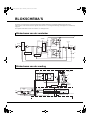
6
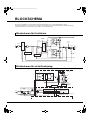
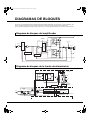
The MX-D1 is a high-power, high-performance PWM (Pulse Width Modulation) digital stereo power amplifier, utilizing
Yamaha’s latest digital power amplifier and switching power supply technologies.
The following block diagrams show the amplifier and power supply circuits.
BLOCK DIAGRAMS
Power Supply Block Diagram
IN
YDA133
SP OUT
YDA134
YDA134
0
V
+B
-B
L
C
Input amp
Active power
control
Output current information
Analog
feedback
Cross
feedback
2.8 MHz
clock input
Constant-gain
PLL
modulator circuit
Real-time
protection
Real-time
protection
Protection
/mute
AC IN
88kHz
2.8MHz
(amp)
OSC
88kHz
100V(on)
200V(off)
+B
-B
OV
+
-
0V
2.8MHz
(amp)
Line filter
Choke
Inrush
protection
circuit
Sub-
transformer
Protection circuit
Microcomputer
Isolator
Right-channel power supply
Driver
Driver
For op-amps
and LSI
Magnetically
-coupled
rectifier circuit
External interface
Amplifier Block Diagram
01-MX-D1_GB_E.fm Page 6 Wednesday, October 22, 2003 2:05 PM

7
English
PWM (Pulse Width Modulation) theoretically produces zero quantization noise, a dynamic range that is dependent only
on circuit technology, and feedback, that combine to make the MX-D1 a superb high-performance power amplifier.
In addition, the Yamaha high-performance, high-speed analog and digital LSI chips are designed to optimize the
performance of the modulator and MOSFET drive circuits that form the heart of the MX-D1.
Active power control system
By continuously monitoring the amplifier’s output current and controlling the maximum continuous output power and
instantaneous dynamic power, the MX-D1 always delivers maximum performance with any load impedance between 2
to 8 ohms.
Constant-gain PLL modulator circuit
With a conventional digital power amplifier, the output is adversely affected by fluctuations in power supply voltage as
the current demands of the amplifier change. The MX-D1’s modulation circuit, consisting of a PLL (Phase Locked Loop)
and modulation circuit, provides a radical solution to this problem.
In response to power supply voltage fluctuations, the constant-gain PLL modulator circuit produces a pulse-width
modulated waveform at a compensated modulation rate suitable for the input signal. In this way, linearity is maintained
and the open-loop gain is fixed, providing stable feedback.
Feedback
Digital output pulses are fed back in a cross-feedback circuit, which improves the performance of the modulator circuit
and the linearity of the output stage, providing very low distortion and a wide dynamic range.
In addition, an analog output signal taken from after the LC output filter is fed back to ensure a high damping factor and
a wide frequency response that is unaffected by the load impedance.
Protection system
The protection system, which guarantees safe operation, includes a super-fast current detection circuit that can measure
the current of a single pulse. It also includes safe operating sequential logic, DC detection, and over-current protection.
Switching power supply
Independent, high-efficiency, low noise resonant-type switching power supplies, developed by Yamaha, are used for the
left and right channels.
In addition, the secondary rectifier circuit has a magnetically coupled rectifier, which resolves issues normally associated
with conventional SEPP (single-ended push-pull) digital amplifiers and allows the MX-D1 to always maintain perfect
symmetry between the positive and negative power supply rails regardless of the direction of the output current.
01-MX-D1_GB_E.fm Page 7 Wednesday, October 22, 2003 2:05 PM

8
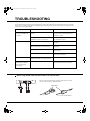
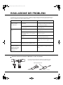
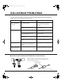
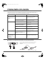
TROUBLESHOOTING
If your MX-D1 does not appear to be working properly, look up the symptoms in the following table. If the symptoms
persist, or are not listed, set the MX-D1 to standby mode, disconnect the AC power cable from the AC outlet, and then
contact the nearest Yamaha dealer.
Symptom Cause Remedy
The MX-D1 does not turn
on when STANDBY/ON
is pressed.
The AC power cable is not connected
properly.
Make sure the AC power cable is connected
properly to the AC IN connector and a
suitable AC outlet.
The component connected to the
CONTROL IN jack is not turned on.
Turn on the component that is connected to
the CONTROL IN jack.
There is no sound. The MX-D1 is not connected properly. Check all connections and correct as
necessary.
The source component connected to the
MX-D1’s input jacks is not set correctly.
Refer to the owner’s manual of the source
component.
The wrong inputs are selected on the MX-
D1.
Use the UNBAL/BAL switch to select the
correct inputs.
The MX-D1’s protection system is active. Check the speaker cables for short circuits
and correct as necessary.
A hum can be heard. The audio pin cable connected to the
UNBALANCE jacks is not fully inserted.
Fully insert the audio pin cable.
The output sounds
unnatural, has a limited
bass range, and poor
stereo image.
The speaker polarity is wrong. Check the polarity of the speaker
connections and correct as necessary.
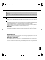
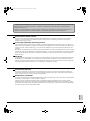
Be sure to attach the clamp filter provided. Open the cover and fit
the core onto the cables as illustrated below.
Clamp filter
When using the RS-232C interface cable or the control cable
(U.S.A. and Canada models)
01-MX-D1_GB_E.fm Page 8 Wednesday, October 22, 2003 3:28 PM

9
English
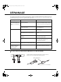
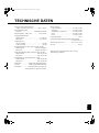
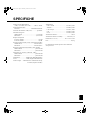
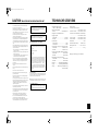
SPECIFICATIONS
Minimum RMS output power
(1 kHz, 1.0 % THD, 4 to 8 Ω) ............... 500 W + 500 W
Dynamic power (IHF)
2/4/6/8 Ω...................................... 1000/1000/850/700 W
Damping factor (1kHz, 8 Ω)........................more than 200
Input sensitivity
UNBALANCE ............................................ 1.3 V/25 kΩ
BALANCE .................................................. 2.2 V/10 kΩ
Frequency response
1 Hz to 100 kHz................................................. ± 3.0 dB
10 Hz to 20 kHz................................................. ± 0.5 dB
Total harmonic distortion (1 kHz, 10 W/8
Ω
, LPF: 20 kHz)
UNBALANCE ....................................less than 0.002 %
BALANCE ..........................................less than 0.002 %
Signal to noise ratio (IHF-A Network, LPF: 20 kHz)
UNBALANCE ................................... more than 120 dB
BALANCE ......................................... more than 120 dB
Channel separation (5.1 kΩ terminated, 1 kHz)
UNBALANCE ................................... more than 100 dB
BALANCE ......................................... more than 100 dB
Modulation......................PWM (Pulse Width Modulation)
Output .............................. SEPP (Single-Ended Push-Pull)
Power source.........Resonant-type switching power supply
(frequency: 88 kHz)
Power supply
U.S.A and Canada models................... AC 120 V, 60 Hz
Australia model ................................... AC 240 V, 50 Hz
U.K. and Europe models ..................... AC 230 V, 50 Hz
China model......................................... AC 220 V, 50 Hz
Korea model ........................................ AC 220 V, 60 Hz
Power consumption.................................................. 350 W
Power consumption in standby mode ........ less than 0.1 W
Dimensions (W x H x D) .....................435 x 75 x 437 mm
..........................................(17-1/8” x 2-7/8” x 17-3/16”)
Weight .............................................10.4 kg (22 lbs. 15 oz)
Specifications are subject to change without notice.
01-MX-D1_GB_E.fm Page 9 Wednesday, October 22, 2003 2:05 PM

• Pour utiliser l’appareil au mieux de ses possibilités, lisez attentivement
ce mode d’emploi. Conservez-le soigneusement pour référence.
• Installez cet appareil audio dans un endroit bien aéré, frais, sec et
propre - à l’abri de la lumière directe du soleil, des sources de chaleur
ou de vibration, des poussières, de l’humidité et du froid. Ménagez un
espace libre d’au moins 30 cm au-dessus, 10 cm à droite et à gauche et
10 cm à l’arrière de l’appareil, pour qu’il soit bien ventilé.
• Placez l’appareil loin des équipements, moteurs et transformateurs
électriques, pour éviter les ronflements parasites.
• N’exposez pas l’appareil à des variations brutales de température, ne le
placez pas dans un environnement très humide (par exemple dans une
pièce contenant un humidificateur) car cela peut entraîner la
condensation d’humidité à l’intérieur de l’appareil qui elle-même peut
être responsable de secousse électrique, d’incendie, de dommage à
l’appareil ou de blessure corporelle.
• Evitez d’installer l’appareil dans un endroit où des objets peuvent
tomber, ainsi que là où l’appareil pourrait être exposé à des
éclaboussures ou des gouttes d’eau. Sur le dessus de l’appareil, ne
placez pas:
• D’autres appareils qui peuvent endommager la surface de l’appareil
ou provoquer sa décoloration.
• Des objets se consumant (par exemple, une bougie) qui peuvent être
responsables d’incendie, de dommage à l’appareil ou de blessure
corporelle.
• Des récipients contenant des liquides qui peuvent être à l’origine de
secousse électrique ou de dommage à l’appareil.
• Ne couvrez pas l’appareil d’un journal, d’une nappe, d’un rideau, etc.
car cela empêcherait l’évacuation de la chaleur. Toute augmentation de
la température intérieure de l’appareil peut être responsible d’incendie,
de dommage à l’appareil ou de blessure corporelle.
• Ne branchez pas la fiche du cordon d’alimentation de l’appareil sur une
prise secteur aussi longtemps que tous les raccordements n’ont pas été
effectués.
• Ne pas faire fonctionner l’appareil à l’envers. Il risquerait de chauffer
et d’être endommagé.
• N’exercez aucune force excessive sur les commutateurs, les boutons et
les cordons.
• Pour débrancher la fiche du cordon d’alimentation au niveau de la prise
secteur, saisissez la fiche et ne tirez pas sur le cordon.
• Ne nettoyez pas l’appareil au moyen d’un solvant chimique, ce qui
pourrait endommager la finition. Utilisez un chiffon sec et propre.
• N’alimentez l’appareil qu’à partir de la tension prescrite. Alimenter
l’appareil sous une tension plus élevée est dangereux et peut être
responsable d’incendie, de dommage à l’appareil ou de blessure
corporelle. YAMAHA ne saurait être tenue responsable des dommages
résultant de l’alimentation de l’appareil sous une tension autre que celle
prescrite.
• Pour empêcher tout dommage causé par les éclairs, déconnectez le
cordon d’alimentation de la prise murale pendant un orage.
• Ne tentez pas de modifier ni de réparer l’appareil. Consultez le service
YAMAHA compétent pour toute réparation qui serait requise. Le
coffret de l’appareil ne doit jamais être ouvert, quelle que soit la raison.
• Si vous envisagez de ne pas vous servir de l’appareil pendant une
longue période (par exemple, pendant les vacances), débranchez la
fiche du cordon d’alimentation au niveau de la prise secteur.
• Avant de contacter un revendeur YAMAHA, lisez la section
“DÉPANNAGE” décrivant des erreurs fréquentes d’utilisation.
• Avant de déplacer l’appareil, appuyez sur le commutateur STANDBY/
ON pour placer l’appareil en veille puis débranchez la fiche du cordon
d’alimentation au niveau de la prise secteur.
Cet appareil n’est pas déconnecté du secteur tant qu’il reste branché à
la prise de courant. Il se trouve alors “en veille”. En mode veille,
l’appareil consomme une très faible quantité de courant.
AVERTISSEMENT
POUR RÉDUIRE LES RISQUES D’INCENDIE OU DE
SECOUSSE ÉLECTRIQUE, N’EXPOSEZ PAS CET APPAREIL À
LA PLUIE OU À L’HUMIDITÉ.
POUR LES CONSOMMATEURS CANADIENS
Pour éviter les chocs électriques, introduire la lame la plus large de la
fiche dans la borne correspondante de la prise et pousser jusqu’au
fond.
Cet appareil numérique de la classe B est conforme à la norme NMB-
003 du Canada.
ATTENTION:
VEUILLEZ LIRE CE QUI SUIT AVANT D’UTILISER L’APPAREIL
02-MX-D1_GB_F.fm Page 0 Wednesday, October 22, 2003 2:06 PM

1
Français
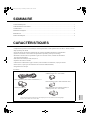
CARACTÉRISTIQUES
• Amplificateur de puissance stéréo numérique de haute performance et d’une puissance max. de 500 W + 500 W (4 à 8 Ω)
• Plage dynamique de 120 dB
• Puces LSI conçues par Yamaha et utilisées dans les circuits de modulation numérique et d’amplification
• Système Active Power Control assurant des performances optimales, quelle que soit la charge
• Modulateur Constant Gain PLL produisant un gain fixe et à boucle ouverte, insensible aux fluctuations
de la tension d’alimentation
• DHT (distorsion harmonique totale) de 0,003 %
• Séparation des canaux de 100 dB
• Alimentation à commutation de type à résonance, à haut rendement et à faible bruit, conçue par Yamaha
• Entrées (RCA) et prises pour enceintes dotées de connecteurs WBT (allemands)
• Design futuriste et ultra-plat
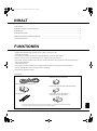
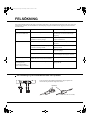
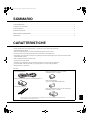
Accessoires
Cordon d’alimentation
Filtre antiparasites (pour le cordon d’alimentation) x 2
Attache pour câbles x 2
Filtre antiparasites (pour le câble audio)
(Modèles pour les E.-U. et le Canada)
Filtre antiparasites (pour le câble interface RS-232C)
Filtre antiparasites (pour câble de contrôle) x 2
(Modèles pour les E.-U. et le Canada)
Veillez à attacher les filtres antiparasites aux câbles indiqués pour éviter des interférences electromagnétiques.
Ouvrez le cache et affixez le tore sur les câbles.
SOMMAIRE
CARACTÉRISTIQUES ............................................................................................................................................................1
COMMANDES ET FONCTIONS ............................................................................................................................................2
CONNEXIONS .........................................................................................................................................................................4
SCHÉMAS LOGIQUES............................................................................................................................................................6
DÉPANNAGE ...........................................................................................................................................................................8
FICHE TECHNIQUES..............................................................................................................................................................9
02-MX-D1_GB_F.fm Page 1 Wednesday, October 22, 2003 2:06 PM

2
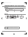
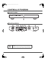
COMMANDES ET FONCTIONS
Face arrière
Face avant
Ce symbole attire votre attention sur une prise délivrant un courant
dangereux.
Pour réduire les risques d’électrocution et d’incendie et éviter les courts-
circuits, suivez scrupuleusement les consignes à la page 5 quand vous
branchez des enceintes.
02-MX-D1_GB_F.fm Page 2 Wednesday, October 22, 2003 2:06 PM

3
Français
1 Commutateur/témoin STANDBY/ON
Ce commutateur sert à mettre le MX-D1 sous tension ou en mode de veille (Standby). L’appa-reil consomme une faible
quantité de courant en mode de veille. Quand vous mettez le MX-D1 sous tension, ce témoin s’allume en bleu, vous
indiquant que le MX-D1 est prêt à l’emploi.
Quand la température à l’intérieur de l’unité monte, ce témoin s’allume alternativement en bleu et en violet. Dans ce cas,
mettez l’unité ailleurs et diminuez le niveau de sortie du préamplificateur etc.
Si une panne est détectée, le MX-D1 active son système de protection et ce témoin s’allume en rouge. Dans ce cas,
mettez immédiatement le MX-D1 en mode de veille et débranchez le cordon d’alimentation de la prise de courant.
Si le témoin reste allumé en rouge lorsque vous rebranchez le cordon d’alimentation au secteur, adressez-vous au
revendeur Yamaha le plus proche.
2 Bornes SPEAKER
Ces bornes servent à brancher vos enceintes. Elles
garantissent une connexion fiable, même en présence
de câbles très épais. Branchez les enceintes aux canaux
gauche et droit, en respectant la polarité (+/–).
Vous pouvez brancher des enceintes d’une impédance
comprise entre 4 et 8 Ω.
3 Prises BALANCE
Reliez ces prises aux sorties XLR symétriques d’une
source avec des câbles XLR.
4 Bouton MUTE
En maintenant ce bouton enfoncé, vous coupez
temporairement la sortie sonore du MX-D1. Si vous
devez modifier une connexion d’entrée alors que le
MX-D1 est sous tension, maintenez ce bouton
enfoncé en effectuant le changement voulu. Cela évite
la production soudaine de bruits forts, de clics et de
grésillements susceptibles d’endommager vos
enceintes.
5 Prises UNBALANCE
Reliez ces prises aux sorties RCA asymétriques
(baptisées “AUDIO OUTPUT” sur le YPC-1) d’une
source avec des câbles RCA/Cinch.
6 Commutateur UNBAL/BAL
Ce commutateur permet d’alterner entre les prises
BALANCE et UNBALANCE.
7 Prise AC IN
Branchez le cordon d’alimentation secteur fourni à
cette prise.
e Commutateur POWER
(Modèles pour l’Australie, le R.-U., l’Europe, la
Chine et la Corée)
Réglez ce commutateur sur la position ON pour
utiliser le MX-D1.
Pour couper l’alimentation secteur, placez ce
commutateur sur la position OFF.
8 Prise RS-232C
9 Commutateur AMP ID
0 Prise CONTROL IN
q Prise CONTROL OUT
w Commutateur POWER/THROUGH
Permet d’étendre les options de pilotage. Pour en
savoir plus, consultez votre revendeur.
02-MX-D1_GB_F.fm Page 3 Wednesday, October 22, 2003 2:06 PM

4
CONNEXIONS
• Préamplificateur
• Matériel de sonorisation
• Lecteur CD avec commande etc.
de volume
Sortie XLR symétrique
Vers une prise
de courant
Enceinte (D) Enceinte (G)
Sortie audio
Lors de la connexion au YPC-1
Sortie RCA asymétrique
(Modèles pour les Etats-Unis et le Canada)
Veillez à attacher les filtres antiparasites au cordon d’alimentation et au câble audio comme indiqué dans l’illustration suivante.
1. Fermez le cache.
2. Serrez le filtre
contre le câble en
vous servant de
l’attache.
Cordon
d’alimentation
Câble audio
(Modèles pour les E.-U. et le Canada)
02-MX-D1_GB_F.fm Page 4 Wednesday, October 22, 2003 3:27 PM

5
Français
Les câbles d’enceintes comportent généralement deux fils
isolés. Pour assurer le respect de la polarité (+/–) lors de la
connexion des enceintes, un de ces deux fils comporte un
isolant de couleur distincte ou est repéré par une ligne.
1. Retirez environ 15mm d’isolant à l’extrémité
des câbles d’enceintes.
2. Torsadez correctement les fils dénudés
pour éviter un court-circuit.
3. Dévissez les vis des bornes SPEAKER.
4. Insérez l’extrémité torsadée des fils
dénudés dans les orifices des bornes
SPEAKER.
5. Resserrez fermement les vis des bornes
SPEAKER.
Si vous utilisez des fiches bananes, resserrez les
extrémités des bornes et insérez-y les fiches.
(Sauf les modèles pour le R.-U., l’Europe et la Corée)
Connexion aux prises BALANCE
Branchez ces prises aux sorties XLR symétriques
d’une source.
L’assignation des broches pour ces prises est indiquée
ci-dessous. Vérifiez dans le mode d’emploi de la
source utilisée si ses prises de sortie correspondent aux
assignations de broches des prises sur l’amplificateur.
Lors de la connexion, alignez les broches et les trous et
insérez la fiche du câble XLR jusqu’à ce que vous
entendiez un déclic.
Pour débrancher, tirez sur la fiche du câble XLR tout
en maintenant enfoncé le levier de la prise BALANCE.
Pour utiliser cette connexion symétrique, placez le
commutateur UNBAL/BAL en position “BAL”.
Connexion aux prises UNBALANCE
Branchez les sorties RCA asymétriques de la source à
ces prises.
Pour utiliser cette connexion asymétrique, placez le
commutateur UNBAL/BAL en position “UNBAL”.
Ne branchez jamais vos éléments simultanément aux
prises BALANCE et UNBALANCE.
Quand toutes les connexions sont effectuées, branchez le
cordon secteur à la prise AC IN puis connectez l’autre
extrémité du cordon à une prise de courant.
Connexion de vos enceintes
15mm
1
2
4
33
5
Rouge: + (positif)
Blanc: – (négatif)
Fiche banane
Connexion de sources
2: chaud
1: masse
3: froid
Attention
Connexion du cordon
d’alimentation secteur
02-MX-D1_GB_F.fm Page 5 Wednesday, October 22, 2003 2:06 PM

6
Le MX-D1 est un amplificateur de puissance stéréo numérique PWM (Pulse Width Modulation) performant bénéficiant des
toutes dernières technologies Yamaha d’amplification de puissance et d’alimentation à commutation.
Les schémas logiques ci-dessous détaillent les circuits d’amplification et d’alimentation.
SCHÉMAS LOGIQUES
Schéma logique de l’alimentation
IN
YDA133
SP OUT
YDA134
YDA134
0
V
+B
-B
L
C
Input amp
Active power
control
Output current information
Analog
feedback
Cross
feedback
2.8 MHz
clock input
Constant-gain
PLL
modulator circuit
Real-time
protection
Real-time
protection
Protection
/mute
AC IN
88kHz
2.8MHz
(amp)
OSC
88kHz
100V(on)
200V(off)
+B
-B
OV
+
-
0V
2.8MHz
(amp)
Line filter
Choke
Inrush
protection
circuit
Sub-
transformer
Protection circuit
Microcomputer
Isolator
Right-channel power supply
Driver
Driver
For op-amps
and LSI
Magnetically
-coupled
rectifier circuit
External interface
Schéma logique de l’amplificateur
02-MX-D1_GB_F.fm Page 6 Wednesday, October 22, 2003 2:06 PM

7
Français
La fonction PWM (Pulse Width Modulation) ne produisant en théorie aucun bruit de quantification, la plage dynamique
qui dépend uniquement de la technologie des circuits et la rétroaction font du MX-D1 un amplificateur de puissance aux
performances exceptionnelles.
En outre, les puces LSI analogiques et numériques de Yamaha, aussi rapides que performantes, sont spécialement conçues
pour optimaliser le rendement du modulateur et des circuits d’amplification MOSFET qui constituent le cœur du MX-D1.
Système Active Power Control
Grâce à la surveillance constante du courant de sortie de l’amplificateur et au contrôle de la pu-issance maximum de
sortie continue ainsi que de la puissance dynamique instantanée, le MX-D1 fournit en permanence un rendement
maximum avec toute impédance de charge comprise entre 2 à 8 Ω.
Circuit de modulateur Constant-gain PLL
Sur un amplificateur de puissance numérique conventionnel, les fluctuations de la tension d’alimentation affectent la
puissance en raison des variations de la consommation de courant. Le circuit de modulation du MX-D1, composé d’un
circuit PLL (Phase Locked Loop) et de modulation, offre une solution radicale à ce problème.
En réponse aux fluctuations de la tension d’alimentation, le circuit de modulateur PLL à gain constant produit une forme
d’onde PWM à une vitesse de compensation appropriée pour le signal d’entrée. Cela permet de maintenir la linéarité et
de travailler avec un gain à boucle ouverte constant, produisant par la même occasion une rétroaction stable.
Rétroaction
Les impulsions de sortie numérique sont réinjectées dans un circuit de réinjection croisée, ce qui augmente les
performances du circuit de modulation et la linéarité de l’étage de sortie. Cela se traduit par une faible distorsion et une
vaste plage dynamique.
De plus, un signal de sortie analogique prélevé derrière le filtre de sortie LC est réinjecté pour augmenter le facteur
d’amortissement et la réponse en fréquences, quelle que soit l’impédance de charge.
Système de protection
La sécurité d’utilisation est assurée par un système de protection comprenant un circuit de détection de courant ultra-
rapide, capable de mesurer le courant d’une seule impulsion. Ce système intègre aussi un dispositif séquentiel logique de
sécurité d’utilisation, un détecteur CC et une protection contre les surcharges.
Alimentation à commutation
Les canaux gauche et droit disposent d’une alimentation indépendante à commutation avec résonance Yamaha à haut
rendement et à faible bruit.
Le circuit redresseur secondaire dispose en outre d’un redresseur à couplage magnétique résolvant les problèmes
habituellement liés aux amplificateurs numériques SEPP (Single-Ended Push-Pull) conventionnels et permettant au MX-
D1 de conserver en permanence une symétrie parfaite entre les lignes d’alimentation positif et négatif, quelle que soit la
direction du courant de sortie.
02-MX-D1_GB_F.fm Page 7 Wednesday, October 22, 2003 2:06 PM

8
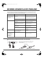
DÉPANNAGE
Si vous pensez que le MX-D1 ne fonctionne pas normalement, vérifiez les symptômes décrits dans le tableau ci-dessous. Si
le problème persiste ou n’est pas décrit ici, placez le MX-D1 en mode de veille, débranchez son cordon d’alimentation de la
prise de courant et adressez-vous au revendeur Yamaha le plus proche.
Symptôme Cause Remède
Le MX-D1 ne se met pas
sous tension quand vous
appuyez sur STANDBY/
ON.
Le cordon d’alimentation secteur n’est pas
correctement branché.
Vérifiez que le cordon d’alimentation
secteur est correctement branché a la prise
AC IN et à une prise de courant appropriée.
La source branchée à la prise CONTROL IN
n’est pas sous tension.
Mettez sous tension l’élément branché à la
prise CONTROL IN.
Pas de son. Le MX-D1 n’est pas correctement branché. Vérifiez toutes les connexions et corrigez-
les si nécessaire.
Les réglages de la source branchée aux
entrées du MX-D1 ne sont pas corrects.
Voyez le mode d’emploi de la source
utilisée.
Vous avez sélectionné les entrées incorrectes
du MX-D1.
Choisissez les entrées correctes avec le
commutateur UNBAL/BAL.
Le système de protection du MX-D1 est
activé.
Vérifiez qu’il n’y a pas de court-circuit aux
câbles d’enceintes et effectuez les
corrections qui s’imposent.
Bourdonnement audible. Les câbles RCA branchés aux prises
UNBALANCE ne sont pas insérés à fond.
Insérez fermement les fiches RCA.
Le son n’est pas naturel,
la plage des graves est
restreinte et l’image
stéréo est pauvre.
La polarité des enceintes est incorrecte. Vérifiez la polarité des connexions
d’enceintes et corrigez-la si nécessaire.
Veillez à attacher le filtre antiparasites fourni. Ouvrez le cache et
affixez le tore sur les câbles comme illustré plus loin.
Filtre antiparasites
Si vous utilisez un câble interface RS-232C ou un câble de contrôle
(Modèles pour les E.-U. et le Canada)
02-MX-D1_GB_F.fm Page 8 Wednesday, October 22, 2003 3:27 PM
Sayfa yükleniyor...
Sayfa yükleniyor...
Sayfa yükleniyor...
Sayfa yükleniyor...
Sayfa yükleniyor...
Sayfa yükleniyor...
Sayfa yükleniyor...
Sayfa yükleniyor...
Sayfa yükleniyor...
Sayfa yükleniyor...
Sayfa yükleniyor...
Sayfa yükleniyor...
Sayfa yükleniyor...
Sayfa yükleniyor...
Sayfa yükleniyor...
Sayfa yükleniyor...
Sayfa yükleniyor...
Sayfa yükleniyor...
Sayfa yükleniyor...
Sayfa yükleniyor...
Sayfa yükleniyor...
Sayfa yükleniyor...
Sayfa yükleniyor...
Sayfa yükleniyor...
Sayfa yükleniyor...
Sayfa yükleniyor...
Sayfa yükleniyor...
Sayfa yükleniyor...
Sayfa yükleniyor...
Sayfa yükleniyor...
Sayfa yükleniyor...
Sayfa yükleniyor...
Sayfa yükleniyor...
Sayfa yükleniyor...
Sayfa yükleniyor...
Sayfa yükleniyor...
Sayfa yükleniyor...
Sayfa yükleniyor...
Sayfa yükleniyor...
Sayfa yükleniyor...
Sayfa yükleniyor...
Sayfa yükleniyor...
Sayfa yükleniyor...
Sayfa yükleniyor...
Sayfa yükleniyor...
Sayfa yükleniyor...
Sayfa yükleniyor...
Sayfa yükleniyor...
Sayfa yükleniyor...
Sayfa yükleniyor...
Sayfa yükleniyor...
Sayfa yükleniyor...
-
 1
1
-
 2
2
-
 3
3
-
 4
4
-
 5
5
-
 6
6
-
 7
7
-
 8
8
-
 9
9
-
 10
10
-
 11
11
-
 12
12
-
 13
13
-
 14
14
-
 15
15
-
 16
16
-
 17
17
-
 18
18
-
 19
19
-
 20
20
-
 21
21
-
 22
22
-
 23
23
-
 24
24
-
 25
25
-
 26
26
-
 27
27
-
 28
28
-
 29
29
-
 30
30
-
 31
31
-
 32
32
-
 33
33
-
 34
34
-
 35
35
-
 36
36
-
 37
37
-
 38
38
-
 39
39
-
 40
40
-
 41
41
-
 42
42
-
 43
43
-
 44
44
-
 45
45
-
 46
46
-
 47
47
-
 48
48
-
 49
49
-
 50
50
-
 51
51
-
 52
52
-
 53
53
-
 54
54
-
 55
55
-
 56
56
-
 57
57
-
 58
58
-
 59
59
-
 60
60
-
 61
61
-
 62
62
-
 63
63
-
 64
64
-
 65
65
-
 66
66
-
 67
67
-
 68
68
-
 69
69
-
 70
70
-
 71
71
-
 72
72


diğer dillerde
- español: Yamaha MX-D1 El manual del propietario
- français: Yamaha MX-D1 Le manuel du propriétaire
- italiano: Yamaha MX-D1 Manuale del proprietario
- svenska: Yamaha MX-D1 Bruksanvisning
- Deutsch: Yamaha MX-D1 Bedienungsanleitung
- English: Yamaha MX-D1 Owner's manual
- dansk: Yamaha MX-D1 Brugervejledning
- Nederlands: Yamaha MX-D1 de handleiding
- română: Yamaha MX-D1 Manualul proprietarului