
ABB general purpose drives
Quick installation guide
ACS580-04 drive modules (250 to 500 kW)
English . . . . . . . 3
English - USA . . 9
Dansk . . . . . . . 17
Deutsch. . . . . . 23
Español. . . . . . 29
Suomi . . . . . . . 35
Français . . . . . 41
Italiano . . . . . . 47
Dutch . . . . . . . 53
Polski . . . . . . . 59
Português . . . . 65
. . . . . 71
Svenska . . . . . 77
Türkçe. . . . . . . 83
中文. . . . . . . . . 89
EN
USA
DA
DE
ES
FI
FR
IT
NL
PL
PT
RU
SV
TR
ZH

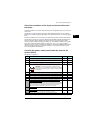
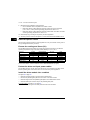
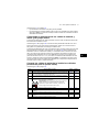
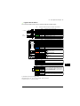
List of related manuals
You can find manuals and other product documents in PDF format on the Internet. See section
Document library on the Internet on the inside of the back cover. For manuals not available in the
Document library, contact your local ABB representative.
The QR code below opens an online listing of the manuals applicable to this product.
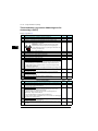
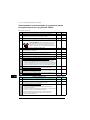
ACS580-04 manuals
Drive hardware manuals and guides Code (English)
ACS580-04 drive modules (200 to 500 kW) hardware
manual
3AXD50000015497
ACS580-04 drive modules (200 to 500 kW) quick
installation guide
3AXD50000015469
ACX-AP-x Assistant control panels user’s manual 3AUA0000085685
ACS-BP-S basic control panel user’s manual 3AXD50000032527
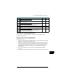
Drive firmware manuals
ACS580 firmware manual 3AXD50000016097
ACS580 drives with standard control program quick
start-up guide
3AXD50000048035
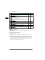
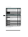
Option manuals and guides
DPMP-02/03 mounting platform for control panels
installation guide
3AUA0000136205
Manuals and quick guides for I/O extension modules,
fieldbus adapters, etc.
CDPI-01 communication adapter module user's manual 3AXD50000009929
CPTC-02 ATEX-certified thermistor protection module,
Ex II (2) GD (+L537+Q971) user's manual
3AXD50000030058
FCAN-01 CANopen adapter module user's manual 3AFE68615500
FCNA-01 ControlNet adapter module user's manual 3AUA0000141650
FDNA-01 DeviceNet™ adapter module user's manual 3AFE68573360
FECA-01 EtherCAT adapter module user's manual 3AUA0000068940
FENA-01/-11/-21 Ethernet adapter module user's
manual
3AUA0000093568
FEPL-02 Ethernet POWERLINK adapter module user's
manual
3AUA0000123527
FPBA-01 PROFIBUS DP adapter module user's manual 3AFE68573271
FSCA-01 RS-485 adapter module user's manual 3AUA0000109533
FOCH du/dt filters hardware manual 3AFE68577519
Tool and maintenance manuals and guides
Drive composer PC tool user's manual 3AUA0000094606
Converter module capacitor reforming instructions 3BFE64059629
NETA-21 remote monitoring tool user's manual 3AUA0000096939
NETA-21 remote monitoring tool installation and startup
guide
3AUA0000096881
3AXD50000015469 Rev C
MUL
EFFECTIVE: 2017-05-12
2017 ABB Oy. All Rights Reserved.

EN – Quick installation guide 3
EN
DA
DE
ES
FI
FR
FR
IT
FR
PL
PT
RU
SV
TR
ZH
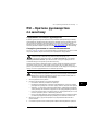
EN – Quick installation guide
Contents of this guide
This guide tells you briefly how to install the drive module into a 600 mm wide cabinet.
For installation examples in different cabinets and more detailed instructions, engineering
guide lines, technical data and complete safety instructions, see the hardware manual
(www.abb.com/drives:
Select Document Library and search for document number
3AXD50000015497 [English]).
Obey the safety instructions
See figure A on page 95. If you ignore these instructions, injury or death, or damage to the
equipment can occur.
WARNING! Handle the drive module carefully. Open the support legs by pressing
each leg a little down and turning it aside (1, 2).
Do not tilt the drive module. It is heavy and its center of gravity is high. The
module will overturn from a sideways tilt of 5 degrees. Do not leave the module
unattended on a sloping floor.
To prevent the drive module from falling, attach its top lifting lugs with chains to the cabinet
frame before you push the module into the cabinet. Work carefully preferably with help
from another person. Keep a constant pressure with one foot on the base of the module to
prevent the module from falling on its back.
WARNING! If you are not a qualified electrician, do not do installation or
maintenance work. Go through these steps before you begin any installation or
maintenance work.
1. Clearly identify the work location.
2. Disconnect all possible voltage sources.
• Open the main disconnector of the drive.
• Open the disconnector of the supply transformer as the main disconnector of the
drive does not remove the voltage from the input busbars of the drive.
• Make sure that reconnection is not possible. Lock the disconnectors to open
position and attach a warning notice to them.
• Disconnect any external power sources from the control circuits before you do
work on the control cables.
• After you disconnect the drive, always wait for 5 minutes to let the intermediate
circuit capacitors discharge before you continue.
3. Protect any other energized parts in the work location against contact.
4. Take special precautions when close to bare conductors.
3AXD50000015469 C

4 EN – Quick installation guide
EN
DA
DE
ES
FI
FR
IT
NL
PL
PT
RU
SV
TR
ZH
5. Measure that the installation is de-energized.
• Use a multimeter with an impedance of at least 1 Mohm.
• Make sure that the voltage between the drive module input power terminals
(L1/U1, L2/V1, L3/W1) and the grounding (PE) busbar is close to 0 V.
• Make sure that the voltage between the drive module UDC+ and UDC- terminals
and the grounding (PE) busbar is close to 0 V.
6. Install temporary grounding as required by the local regulations.
7. Ask for a permit to work from the person in control of the electrical installation work.
Select the power cables
Size the power cables according to local regulations to carry the nominal current given on
the type designation label of your drive.
Ensure the cooling
See table G on page 96 for the losses and the cooling air flow through the drive. The
allowed operating temperature range of the drive without derating is -15 to +40 °C.
Protect the drive and input power cables
See table G on page 96.
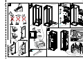
Install the drive module into a cabinet
See figure B on page 95:
• Install the punched section to the back of the cabinet frame.
• Remove the pedestal guide plate from the bottom of the drive module.
• Install the support rails and pedestal guide plate to the cabinet bottom frame.
• Install the telescopic insertion ramp to the pedestal guide plate.
For option +B051: See figure C on page 95:
• Remove the sheeting from the clear plastic shrouds from both sides.
See figure D on page 95:
• Install the mounting bracket to the drive module.
• For option +B051:
• Install the bottom grille to the drive module if there is no bottom plate in the cabinet
and degree of protection of IP20 is needed for the drive module from the bottom
side.
• Install the top metallic shroud to the drive module.
• Install the back shrouds to the drive module.
See figure E on page 95:
• Attach the drive module to the cabinet frame with chains.
• Push the drive module into the cabinet along the telescopic insertion ramp.
• Remove the ramp.
See figure F on page 95:
• Attach the drive module to the pedestal guide plate.
• Attach the drive module from top to the punched section at the cabinet back. Note:
The mounting bracket grounds the drive module to the cabinet frame.

EN – Quick installation guide 5
EN
DA
DE
ES
FI
FR
FR
IT
FR
PL
PT
RU
SV
TR
ZH
Check the insulation of the input and motor cables and
the motor
Check the insulation of the input cable according to local regulations before you connect it
to the drive.
See figure H on page 96. Ground the motor cable shield at the motor end. For minimal
interference, make a 360-degree grounding at the cable lead-through, or keep the pig tail
short.
Check the insulation of the motor and motor cable when the motor cable is disconnected
from the drive, see figure I on page 96. Measure the insulation resistance between each
phase conductor and then between each phase conductor and the Protective Earth
conductor using a measuring voltage of 1000 V DC. The insulation resistance of an ABB
motor must exceed 100 Mohm (reference value at 25 °C or 77 °F). For the insulation
resistance of other motors, consult the manufacturer’s instructions. Note: Moisture inside
the motor casing will reduce the insulation resistance. If you suspect moisture, dry the
motor and repeat the measurement.
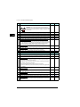
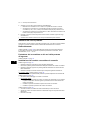
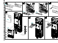
Connect the power cables (and install the shrouds for
option +B051)
See figure G on page 96.
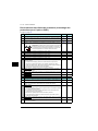
Step Task (motor cables) Figure Page
1 Install the grounding terminal to the drive module base. J96
2 Run the motor cables to the cabinet. Ground the cable shields 360 degrees at
the cabinet lead-through.
K96
3 Connect the twisted shields of the motor cables to the grounding terminal. L96
4 Screw in and tighten the insulators to the drive module by hand. Install the
T3/W2 connection terminal to the insulators.
WARNING! Do not use longer screws or bigger tightening
torque than given in the installation drawing. They can damage
the insulator and cause dangerous voltage to be present at the
module frame.
M96
5 Connect the phase conductors to the T3/W2 terminal. N96
6 Install the T2/V2 connection terminal to the insulators. See the warning in step 4. - -
7 Connect the phase conductors to the T2/V2 connection terminal. - -
8 Install the T1/U2 connection terminal to the insulators. See the warning in step 4. - -
9 Connect the phase conductors to the T1/U2 terminal. - -
10 For option +B051 (if there is no bottom plate in the cabinet and degree of
protection of IP20 is needed):
• Step drill carefully sufficiently big holes to the inner clear plastic shrouds for the
motor cables to the connected. Smooth the hole edges. Cut the shroud from the
holes to the edge to make it possible to put the shroud around the cables.
• Remove the plastic sheeting from the shrouds from both sides.
O97
11 For option +B051: Put the inner clear plastic shrouds of figure O around the
motor cables.
P97
12 For option +B051: Remove the plastic sheeting from the output clear plastic
shroud from both sides. Install the shroud to the drive module.
Q97
13 For option +B051: Install the lower front cover to the drive module. Q97

6 EN – Quick installation guide
EN
DA
DE
ES
FI
FR
IT
NL
PL
PT
RU
SV
TR
ZH
Install the air baffles
See figure W on page 98 and Guidelines for planning the cabinet installation in the
hardware manual.
Connect the control cables
See figure X on page 98.
1. Ground the outer shields of all external control cables 360 degrees at the cabinet lead-
through.
2. Ground the pair-cable shields of external control cables to a grounding clamp below
the control unit. Leave the other end of the shields unconnected or ground them
indirectly via a high-frequency capacitor with a few nanofarads, eg, 3.3 nF / 630 V.
3. Connect the conductors to the appropriate terminals of the control unit. See page 7.
4. Wire the optional modules if included in the delivery.
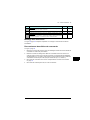
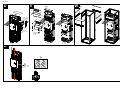
Step Task (input cables) Figure Page
1 Ground the input cable shields (if present) 360 degrees at the cabinet lead-through. - -
2 Connect the twisted shields of the input cables and separate ground cable (if
present) to the cabinet grounding busbar.
- -
3 For option +B051:
• Step drill carefully sufficiently big holes to the lead-through clear plastic
shroud for the cables to the connected.
• Align the holes in the vertical direction according to the alignment holes in
the shroud. Smooth the hole edges.
• Remove the plastic sheeting from both sides of the shroud.
• Attach the cables firmly to the cabinet frame to prevent chafing against the
hole edges.
R97
4 For option +B051: Put the conductors of the input cables through the drilled
holes in the clear plastic shroud.
S97
5 Connect the input power cable conductors to the L1/U1, L2/V1 and L3/W1
connection busbars.
T97
6 For option +B051: Move the lead-through clear plastic shroud along input
cables to its final position. Install the front clear plastic shroud.
U98
7 Install the upper front cover. U98
8 Remove the cardboard protective covering from the drive module air outlet. U98
9 For option +B051: Cut the hole for the lead-through clear plastic shroud in the
side clear plastic shroud. Install the side and top clear plastic shrouds to the
drive module.
V98

EN – Quick installation guide 7
EN
DA
DE
ES
FI
FR
FR
IT
FR
PL
PT
RU
SV
TR
ZH
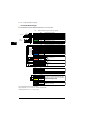
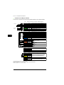
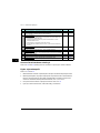
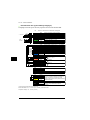
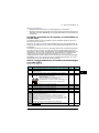
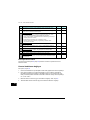
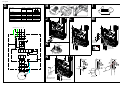
Default I/O connections
The default I/O connections of the ABB Standard macro are shown below.
Total load capacity of the Auxiliary voltage output +24V (X2:10) is 6.0 W (250 mA / 24 V DC).
Terminal sizes: 0.14…2.5 mm
2
(all terminals)
Tightening torques: 0.5…0.6 N·m (0.4 lbf·ft)
max.
500 ohm
1…10 kohm
XI Reference voltage and analog inputs and outputs
1 SCR Signal cable shield (screen)
2 AI1 Output frequency reference: 0…10 V
3 AGND Analog input circuit common
4 +10V Reference voltage 10 V DC
5 AI2 Not configured
6 AGND Analog input circuit common
7 AO1 Output frequency: 0…20 mA
8 AO2 Motor current: 0…20 mA
9 AGND Analog output circuit common
X2 & X3 Aux. voltage output and programmable digital inputs
10 +24V Aux. voltage output +24 V DC, max. 250 mA
11 DGND Auxiliary voltage output common
12 DCOM Digital input common for all
13 DI1 Stop (0) / Start (1)
14 DI2 Forward (0) / Reverse (1)
15 DI3 Constant frequency selection
16 DI4 Constant frequency selection
17 DI5
Ramp set 1 (0) / Ramp set 2 (1)
18 DI6 Not configured
X6, X7, X8 Relay outputs
19 RO1C Ready run
250 V AC / 30 V DC
2 A
20 RO1A
21 RO1B
22 RO2C Running
250 V AC / 30 V DC
2 A
23 RO2A
24 RO2B
25 RO3C Fault (-1)
250 V AC / 30 V DC
2 A
26 RO3A
27 RO3B
X5 EIA-485 Modbus RTU
29 B+
Embedded Modbus RTU (EIA-485).
30 A-
31 DGND
S4 TERM Serial data link termination switch
S5 BIAS Serial data link bias resistors switch
X4 Safe torque off
34 OUT1
Safe torque off. Factory connection. Both
circuits must be closed for the drive to start.
See chapter Safe torque off function in
ACS580-04 hardware manual
(3AXD50000015497 [English]).
35 OUT2
36 SGND
37 IN1
38 IN2
X10 24 V AC/DC
40
24 V AC/DC+ in
Ext. 24V AC/DC input to power up the control unit
when the main supply is
disconnected.
41
24 V AC/DC- in

8 EN – Quick installation guide
EN
DA
DE
ES
FI
FR
IT
NL
PL
PT
RU
SV
TR
ZH

EN – USA Quick installation guide 9
USA
DA
DE
ES
FI
FR
IT
PL
PT
RU
SV
TR
ZH
EN – USA Quick installation
guide
Contents of this guide
This guide tells you briefly how to install the drive module into a 600 mm wide cabinet.
For installation examples in different cabinets and more detailed instructions, engineering
guide lines, technical data and complete safety instructions, see the hardware manual
(www.abb.com/drives:
Select Document Library and search for document number
3AXD50000015497 [English]).
Obey the safety instructions
See figure A on page 95. If you ignore these instructions, injury or death, or damage to the
equipment can occur.
WARNING! Handle the drive module carefully. Open the support legs by pressing
each leg a little down and turning it aside (1, 2).
Do not tilt the drive module. It is heavy and its center of gravity is high. The
module will overturn from a sideways tilt of 5 degrees. Do not leave the module
unattended on a sloping floor.
To prevent the drive module from falling, attach its top lifting lugs with chains to the cabinet
frame before you push the module into the cabinet. Work carefully preferably with help
from another person. Keep a constant pressure with one foot on the base of the module to
prevent the module from falling on its back.
WARNING! If you are not a qualified electrician, do not do installation or
maintenance work. Go through these steps before you begin any installation or
maintenance work.
5. Clearly identify the work location.
6. Disconnect all possible voltage sources.
• Open the main disconnector of the drive.
• Open the disconnector of the supply transformer as the main disconnector of the
drive does not remove the voltage from the input busbars of the drive.
• Make sure that reconnection is not possible. Lock the disconnectors to open
position and attach a warning notice to them.
• Disconnect any external power sources from the control circuits before you do
work on the control cables.
• After you disconnect the drive, always wait for 5 minutes to let the intermediate
circuit capacitors discharge before you continue.
7. Protect any other energized parts in the work location against contact.
8. Take special precautions when close to bare conductors.
3AXD50000015469 C

10 EN – USA Quick installation guide
USA
DA
DE
ES
FI
FR
IT
NL
PL
PT
RU
SV
TR
ZH
9. Measure that the installation is de-energized.
• Use a multimeter with an impedance of at least 1 Mohm.
• Make sure that the voltage between the drive module input power terminals
(L1/U1, L2/V1, L3/W1) and the grounding (PE) busbar is close to 0 V.
• Make sure that the voltage between the drive module UDC+ and UDC- terminals
and the grounding (PE) busbar is close to 0 V.
10. Install temporary grounding as required by the local regulations.
11. Ask for a permit to work from the person in control of the electrical installation work.
Select the power cables
Size the power cables according to local regulations to carry the nominal current given on
the type designation label of your drive.
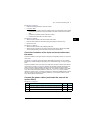
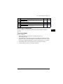
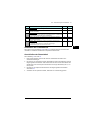
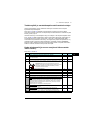
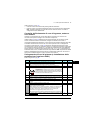
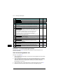
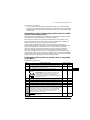
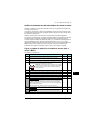
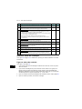
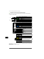
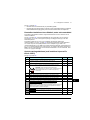
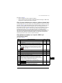
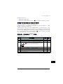
Ensure the cooling and fuses (UL)
See the table below for the losses and cooling air flow through the drive. The allowed
operating temperature range of the drive without derating is -15 to +40 °C.
For more information, see the hardware manual 3AXD50000048677 (English).
Protect the drive and input power cables
See the table above for the UL class fuses for branch circuit protection per NEC. Check
that the operating time of the fuse is below 0.1 seconds. Obey local regulations.
Install the drive module into a cabinet
See figure B on page 95:
• Install the punched section to the back of the cabinet frame.
• Remove the pedestal guide plate from the bottom of the drive module.
• Install the support rails and pedestal guide plate to the cabinet bottom frame.
• Install the telescopic insertion ramp to the pedestal guide plate.
For option +B051: See figure C on page 95:
• Remove the sheeting from the clear plastic shrouds from both sides.
Drive type Air flow Heat dissipation UL class Fuse
ft
3
/min W Type
ACS580-505A-4 707 5602 T JJS-600
ACS580-585A-4 707 6409 L A4BY800
ACS580-650A-4 707 8122 L A4BY800
ACS580-725A-4 707 8764 L A4BY800
ACS580-820A-4 707 9862 L A4BY900
ACS580-880A-4 848 10578 L A4BY1000

EN – USA Quick installation guide 11
USA
DA
DE
ES
FI
FR
IT
PL
PT
RU
SV
TR
ZH
See figure D on page 95:
• Install the mounting bracket to the drive module.
• For option +B051:
• Install the bottom grille to the drive module if there is no bottom plate in the cabinet
and degree of protection of IP20 is needed for the drive module from the bottom
side.
• Install the top metallic shroud to the drive module.
• Install the back shrouds to the drive module.
See figure E on page 95:
• Attach the drive module to the cabinet frame with chains.
• Push the drive module into the cabinet along the telescopic insertion ramp.
• Remove the ramp.
See figure F on page 95:
• Attach the drive module to the pedestal guide plate.
• Attach the drive module from top to the punched section at the cabinet back. Note:
The mounting bracket grounds the drive module to the cabinet frame.
Check the insulation of the input and motor cables and
the motor
Check the insulation of the input cable according to local regulations before you connect it
to the drive.
See figure H on page 96. Ground the motor cable shield at the motor end. For minimal
interference, make a 360-degree grounding at the cable lead-through, or keep the pig tail
short.
Check the insulation of the motor and motor cable when the motor cable is disconnected
from the drive, see figure I on page 96. Measure the insulation resistance between each
phase conductor and then between each phase conductor and the Protective Earth
conductor using a measuring voltage of 1000 V DC. The insulation resistance of an ABB
motor must exceed 100 Mohm (reference value at 25 °C or 77 °F). For the insulation
resistance of other motors, consult the manufacturer’s instructions. Note: Moisture inside
the motor casing will reduce the insulation resistance. If you suspect moisture, dry the
motor and repeat the measurement.
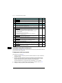
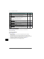
Connect the power cables (and install the shrouds for
option +B051)
See figure G on page 96.
Step Task (motor cables) Figure Page
1 Install the grounding terminal to the drive module base. J96
2 Run the motor cables to the cabinet. Ground the cable shields 360 degrees at
the cabinet lead-through.
K96
3 Connect the twisted shields of the motor cables to the grounding terminal. L96

12 EN – USA Quick installation guide
USA
DA
DE
ES
FI
FR
IT
NL
PL
PT
RU
SV
TR
ZH
4 Screw in and tighten the insulators to the drive module by hand. Install the
T3/W2 connection terminal to the insulators.
WARNING! Do not use longer screws or bigger tightening
torque than given in the installation drawing. They can damage
the insulator and cause dangerous voltage to be present at the
module frame.
M96
5 Connect the phase conductors to the T3/W2 terminal. N96
6 Install the T2/V2 connection terminal to the insulators. See the warning in step 4. - -
7 Connect the phase conductors to the T2/V2 connection terminal. - -
8 Install the T1/U2 connection terminal to the insulators. See the warning in step 4. - -
9 Connect the phase conductors to the T1/U2 terminal. - -
10 For option +B051 (if there is no bottom plate in the cabinet and degree of
protection of IP20 is needed):
• Step drill carefully sufficiently big holes to the inner clear plastic shrouds for the
motor cables to the connected. Smooth the hole edges. Cut the shroud from the
holes to the edge to make it possible to put the shroud around the cables.
• Remove the plastic sheeting from the shrouds from both sides.
O97
11 For option +B051: Put the inner clear plastic shrouds of figure O around the
motor cables.
P97
12 For option +B051: Remove the plastic sheeting from the output clear plastic
shroud from both sides. Install the shroud to the drive module.
Q97
13 For option +B051: Install the lower front cover to the drive module. Q97
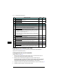
Step Task (input cables) Figure Page
1 Ground the input cable shields (if present) 360 degrees at the cabinet lead-through. - -
2 Connect the twisted shields of the input cables and separate ground cable (if
present) to the cabinet grounding busbar.
- -
3 For option +B051:
• Step drill carefully sufficiently big holes to the lead-through clear plastic
shroud for the cables to the connected.
• Align the holes in the vertical direction according to the alignment holes in
the shroud. Smooth the hole edges.
• Remove the plastic sheeting from both sides of the shroud.
• Attach the cables firmly to the cabinet frame to prevent chafing against the
hole edges.
R97
4 For option +B051: Put the conductors of the input cables through the drilled
holes in the clear plastic shroud.
S97
5 Connect the input power cable conductors to the L1/U1, L2/V1 and L3/W1
connection busbars.
T97
6 For option +B051: Move the lead-through clear plastic shroud along input
cables to its final position. Install the front clear plastic shroud.
U98
7 Install the upper front cover. U98
8 Remove the cardboard protective covering from the drive module air outlet. U98
9 For option +B051: Cut the hole for the lead-through clear plastic shroud in the
side clear plastic shroud. Install the side and top clear plastic shrouds to the
drive module.
V98
Step Task (motor cables) Figure Page

EN – USA Quick installation guide 13
USA
DA
DE
ES
FI
FR
IT
PL
PT
RU
SV
TR
ZH
Install the air baffles
See figure W on page 98 and Guidelines for planning the cabinet installation in the
hardware manual.
Connect the control cables
See figure X on page 98.
1. Ground the outer shields of all external control cables 360 degrees at the cabinet lead-
through.
2. Ground the pair-cable shields of external control cables to a grounding clamp below
the control unit. Leave the other end of the shields unconnected or ground them
indirectly via a high-frequency capacitor with a few nanofarads, eg, 3.3 nF / 630 V.
3. Connect the conductors to the appropriate terminals of the control unit. See page 14.
4. Wire the optional modules if included in the delivery.

14 EN – USA Quick installation guide
USA
DA
DE
ES
FI
FR
IT
NL
PL
PT
RU
SV
TR
ZH
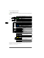
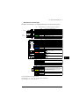
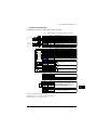
Default I/O connections
The default I/O connections of the ABB Standard macro are shown below.
Total load capacity of the Auxiliary voltage output +24V (X2:10) is 6.0 W (250 mA / 24 V DC).
Terminal sizes: 0.14…2.5 mm
2
(all terminals)
Tightening torques: 0.5…0.6 N·m (0.4 lbf·ft)
max.
500 ohm
1…10 kohm
XI Reference voltage and analog inputs and outputs
1 SCR Signal cable shield (screen)
2 AI1 Output frequency reference: 0…10 V
3 AGND Analog input circuit common
4 +10V Reference voltage 10 V DC
5 AI2 Not configured
6 AGND Analog input circuit common
7 AO1 Output frequency: 0…20 mA
8 AO2 Motor current: 0…20 mA
9 AGND Analog output circuit common
X2 & X3 Aux. voltage output and programmable digital inputs
10 +24V Aux. voltage output +24 V DC, max. 250 mA
11 DGND Auxiliary voltage output common
12 DCOM Digital input common for all
13 DI1 Stop (0) / Start (1)
14 DI2 Forward (0) / Reverse (1)
15 DI3 Constant frequency selection
16 DI4 Constant frequency selection
17 DI5
Ramp set 1 (0) / Ramp set 2 (1)
18 DI6 Not configured
X6, X7, X8 Relay outputs
19 RO1C Ready run
250 V AC / 30 V DC
2 A
20 RO1A
21 RO1B
22 RO2C Running
250 V AC / 30 V DC
2 A
23 RO2A
24 RO2B
25 RO3C Fault (-1)
250 V AC / 30 V DC
2 A
26 RO3A
27 RO3B
X5 EIA-485 Modbus RTU
29 B+
Embedded Modbus RTU (EIA-485).
30 A-
31 DGND
S4 TERM Serial data link termination switch
S5 BIAS Serial data link bias resistors switch
X4 Safe torque off
34 OUT1
Safe torque off. Factory connection. Both
circuits must be closed for the drive to start.
See chapter Safe torque off function in
ACS580-04 hardware manual
(3AXD50000015497 [English]).
35 OUT2
36 SGND
37 IN1
38 IN2
X10 24 V AC/DC
40
24 V AC/DC+ in
Ext. 24V AC/DC input to power up the control unit
when the main supply is
disconnected.
41
24 V AC/DC- in

EN – USA Quick installation guide 15
USA
DA
DE
ES
FI
FR
IT
PL
PT
RU
SV
TR
ZH
UL checklist
• The drive must be installed in clean air according to enclosure classification. Cooling air
must be clean, free from corrosive materials and electrically conductive dust.
• The maximum ambient air temperature is 40 °C (104 °F) at rated current. The current is
derated for 40 to 55 °C (104 to 131 °F).
• The drive is suitable for use in a circuit capable of delivering not more than 100,000 rms
symmetrical amperes, 600 V maximum. The ampere rating is based on tests done
according to UL 508C.
• The cables located within the motor circuit must be rated for at least 75 °C (167 °F) in
UL-compllant installations.
• The input cable must be protected with fuses. Circuit breakers must not be used without
fuses in the USA. Suitable IEC (class aR) fuses and UL (class T) fuses are listed in the
hardware manual. For suitable circuit breakers, contact your local ABB representative.
• For installation in the United States, branch circuit protection must be provided in
accordance with the National Electrical Code (NEC) and any applicable local codes. To
fulfill this requirement, use the UL classified fuses.
• For installation in Canada, branch circuit protection must be provided in accordance
with the Canadian Electrical Code and any applicable provincial codes. To fulfill this
requirement, use the UL classified fuses.
• The drive provides overload protection in accordance with the National Electrical Code
(NEC).

16 EN – USA Quick installation guide
USA
DA
DE
ES
FI
FR
IT
NL
PL
PT
RU
SV
TR
ZH

DA – Hurtig installations-vejledning 17
DA
DA
DE
ES
FI
FR
IT
PL
PT
RU
SV
TR
ZH
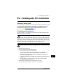
DA – Hurtig installations-
vejledning
Indholdet i denne vejledning
Denne vejledning giver dig en kortfattet vejledning til, hvordan du kan installere
frekvensomformermodulet i et 600 mm bredt kabinet. Hvis du vil se installationseksempler
for andre kabinetter og få mere detaljerede instruktioner, tekniske retningslinjer, tekniske
data og komplette sikkerhedsinstruktioner, kan du se hardwaremanualen
(www.abb.com/drives:
Vælg Document Library, og søg efter dokumentnummer
3AXD50000015497 [på engelsk]).
Overhold sikkerhedsinstruktionerne
Se figur A på side 95. Hvis disse instruktioner ignoreres, kan det resultere i personskader,
dødsfald eller skade på udstyret.
ADVARSEL! Håndter frekvensomformermodulet forsigtigt. Åbn støttebenene ved
at trykke lidt ned på hvert ben og dreje det til side (1, 2).
Frekvensomformermodulet må ikke vippes. Det er tungt og har et højt tyngdepunkt.
Enheden vil vælte, hvis den udsættes for en sidelæns hældning på 5 grader. Efterlad ikke
modulet uovervåget på et gulv, der hælder.
For at forhindre, at frekvensomformermodulet i at falde, skal du fastgøre toppens løfteøjer
med kæder til kabinetrammen, inden du skubber det ind i kabinettet. Udfør arbejdet forsig-
tigt, helst med hjælp fra en anden person. Hold et konstant tryk med én fod på modulets
fod for at forhindre modulet i at falde bagover.
ADVARSEL! Installations- eller vedligeholdelsesarbejde må kun udføres
af uddannede elektrikere. Følg disse trin, inden installations- eller
vedligeholdelsesarbejde påbegyndes.
1. Identificer arbejdsstedet tydeligt.
2. Frakobl alle spændingskilder.
• Åbn frekvensomformerens hovedafbryder.
• Hvis afbryderen til forsyningstransformeren åbnes som hovedafbryder
til frekvensomformeren, er der stadig spænding på frekvensomformerens
indgangseffektskinner.
• Sørg for, at gentilkobling ikke er mulig. Lås afbryderne i åben position, og fastgør
en advarsel til dem.
• Frakobl eventuelle eksterne spændingskilder fra styrekredsene, inden der udføres
arbejde på styrekablerne.
3AXD50000015469 C

18 DA – Hurtig installations-vejledning
DA
DA
DE
ES
FI
FR
IT
NL
PL
PT
RU
SV
TR
ZH
• Efter at spændingen til frekvensomformeren er afbrudt, skal du altid vente i 5
minutter på, at kondensatorerne i mellemkredsen aflades, inden du fortsætter
3. Beskyt eventuelle andre strømførende dele i arbejdsområdet mod kontakt.
4. Tag særlige forholdsregler, når der arbejdes i nærheden af ikke-isolerede ledere.
5. Kontroller, at installationen ikke er strømførende.
• Brug et multimeter med en impedans på mindst 1 Mohm.
• Sørg for, at spændingen mellem frekvensomformermodulets indgangseffektterminaler
(L1/U1, L2/V1, L3/W1) og jordskinnen (PE) er tæt på 0 V.
• Sørg for, at spændingen mellem frekvensomformermodulets terminaler UDC+ og
UDC- og jordskinnen (PE) er tæt på 0 V.
6. Installer midlertidig jordforbindelse som påkrævet i henhold til lokale bestemmelser.
7. Bed om tilladelse til at arbejde fra den person, der er ansvarlig for det
elektriskeinstallationsarbejde.
Vælg effektkabler
Vælg en størrelse til kablerne i henhold til lokale forskrifter til at bære den nominelle strøm,
der er anført på mærket med typebetegnelsen på din frekvensomformer.
Sørg for kølingen
Se tabel G på side 104 for tabene og frekvensomformeren gennemstrømning af kølende luft.
Frekvensomformerens tilladte driftstemperaturområde uden reduktion er -15 til +40 °C.
Beskyt frekvensomformeren og netkabler
Se tabellen G på side 96.
Installer frekvensomformermodulet i et kabinet
Se figur B på side 95:
• Monter den hullede sektion bagerst på kabinetrammen.
• Fjern soklens styreplade fra bunden af frekvensomformermodulet.
• Monter styreskinner og soklens styreplade til kabinettets bundramme.
• Monter den teleskopiske rampe til indsættelse på soklens styreplade.
For ekstraudstyr +B051: Se figur C på side 95:
• Fjern beskyttelsen fra de gennemsigtige plastikafdækninger på begge sider.
Se figur D på side 95:
• Monter monteringsbeslaget på frekvensomformermodulet.
• For ekstraudstyr +B051:
• Monter det nederste gitter på frekvensomformodulet, hvis der ikke findes en
bundplade i kabinettet og der skal anvendes IP20-beskyttelsesgrad for
frekvensomformermodulet fra nederste side.
• Monter metaltopafdækning på frekvensomformermodulet.
• Monter bagsideafdækning på frekvensomformermodulet.

DA – Hurtig installations-vejledning 19
DA
DA
DE
ES
FI
FR
IT
PL
PT
RU
SV
TR
ZH
Se figur E på side 95:
• Fastgør frekvensomformermodulet med kæder til kabinetrammen.
• Skub frekvensomformermodulet ind i kabinettet langs den teleskopiske rampe.
• Fjern rampen.
Se figur F på side 95:
• Fastgør frekvensomformermodulet til soklens styreplade.
• Fastgør frekvensomformermodulet fra top til den hullede sektion på kabinetbagsiden.
Bemærk! Monteringsbeslaget fastgør frekvensomformermodulet til kabinettets ramme.
Kontroller isoleringen på input- og motorkabler samt motoren
Kontrollér isoleringen af indgangskablet i overensstemmelse med de nationale forskrifter,
inden du tilslutter frekvensomformeren.
Se figur H på side 96: Tilslut motorkabelskærmen i motorenden. Opnå minimal interferens
ved at lave en 360 graders jording ved kabelgennemføringen og holde den snoede
kobberskærm kort.
Kontroller isoleringen af motor og motorkabel, når motorkablet er koblet fra
frekvensomformeren. Se figur I på side 104. Mål isolationsmodstanden mellem hver
faseleder og derefter mellem hver faseleder og beskyttelsesjordens leder med en
målespænding på 1000 V DC. Isolationsmodstanden på en ABB-motor skal være større
end 100 Mohm (referenceværdi ved 25 °C eller 77 °F). Oplysninger om
isolationsmodstanden på andre motorer kan findes i producentens vejledninger.
Bemærk! Fugt inden i motorhuset reducerer isolationsmodstanden. Hvis du har mistanke
om fugt, skal motoren tørres, og målingen gentages.

20 DA – Hurtig installations-vejledning
DA
DA
DE
ES
FI
FR
IT
NL
PL
PT
RU
SV
TR
ZH
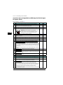
Tilslut netkabler (og monter afdækningerne for
ekstraudstyr +B051)
Se figur G på side 96:
Trin Opgaver (motorkabler) Figur Side
1 Monter jordterminalen på frekvensomformermodulets fod. J96
2
Træk motorkablerne til kabinettet Jord kabelskærmen 360 gader ved kabelindgangen.
K96
3 Forbind de snoede dele af motorkabelskærmene med jordterminalen. L96
4
Skru og spænd med hånden isolationen på frekvensomformermodulet. Monter
T3/W2-tilslutningsterminalen i isolationen.
ADVARSEL! Undgå at bruge længere skruer eller større
tilspændingsmoment end angivet i monteringstegningen.
De kan ødelægge isolationen og forårsage at der findes farlig
spænding i modulrammen.
M96
5 Tilslut faselederne til T3/W2-terminalen. N96
6 Monter T2/V2-tilslutningsterminalen i isolationen. Se advarslen i trin 4. - -
7 Tilslut faselederne til T2/V2-tilslutningsterminalen. - -
8 Monter T1/U2-tilslutningsterminalen i isolationen. Se advarslen i trin 4. - -
9 Tilslut faselederne til T1/U2-terminalen. - -
10 For ekstraudstyr +B051 (hvis der ikke er nogen bundplade i kabinettet og der
skal anvendes IP20-beskyttelsesgrad):
• Bor trinvist og forsigtigt huller af passende størrelse gennem den klare indre
plastikafdækning hvor kablerne skal forbindes. Udglat hullernes kanter.
Skær afdækningen fra hullerne til kanten for at gøre det muligt at sætte
afdækningen på kablerne.
Fjern plastikbeskyttelsen fra de gennemsigtige plastikafdækninger på begge sider.
O97
11
For ekstraudstyr +B051:
Monter den indre klare plastikafdækning i figur O
omkring motorkablerne.
P97
12 For ekstraudstyr +B051: Fjern plastikbeskyttelsen fra de gennemsigtige
plastikafdækninger på begge sider. Monter afdækningen på
frekvensomformermodulet.
Q97
13
For ekstraudstyr +B051:
Monter nederste frontafdækning på
frekvensomformermodulet.
Q97
Trin Opgaver (indgangskabler) Figur Side
1 Jord indgangskabelskærmene (hvis de findes) 360 gader ved kabelindgangen. - -
2
Forbind de snoede dele af indgangskablerne og de separate jordingskabler
(hvis de findes) til kabinettets jordskinne.
- -
3 For ekstraudstyr +B051:
• Bor trinvist og forsigtigt huller af passende størrelse gennem den klare
plastikafdækning hvor kablerne skal forbindes.
• Hullerne justeres i lodret retning så de passer til justeringshullerne i
afdækningen. Udglat hullernes kanter.
• Fjern plastikbeskyttelsen på begge sider af afdækningen.
• Fastgør kablerne sikkert til kabinetrammen for at forhindre, at de ødelægges
af gnidning mod hullernes kanter.
R97
4
For ekstraudstyr +B051:
Træk lederne for indgangskablerne gennem de
borede huller i den klare plastafdækning.
S97
5
Forbind netkablernes indgangsledere til forbindelsesskinnerne L1/U1, L2/V1
og L3/W1.
T97
Sayfa yükleniyor ...
Sayfa yükleniyor ...
Sayfa yükleniyor ...
Sayfa yükleniyor ...
Sayfa yükleniyor ...
Sayfa yükleniyor ...
Sayfa yükleniyor ...
Sayfa yükleniyor ...
Sayfa yükleniyor ...
Sayfa yükleniyor ...
Sayfa yükleniyor ...
Sayfa yükleniyor ...
Sayfa yükleniyor ...
Sayfa yükleniyor ...
Sayfa yükleniyor ...
Sayfa yükleniyor ...
Sayfa yükleniyor ...
Sayfa yükleniyor ...
Sayfa yükleniyor ...
Sayfa yükleniyor ...
Sayfa yükleniyor ...
Sayfa yükleniyor ...
Sayfa yükleniyor ...
Sayfa yükleniyor ...
Sayfa yükleniyor ...
Sayfa yükleniyor ...
Sayfa yükleniyor ...
Sayfa yükleniyor ...
Sayfa yükleniyor ...
Sayfa yükleniyor ...
Sayfa yükleniyor ...
Sayfa yükleniyor ...
Sayfa yükleniyor ...
Sayfa yükleniyor ...
Sayfa yükleniyor ...
Sayfa yükleniyor ...
Sayfa yükleniyor ...
Sayfa yükleniyor ...
Sayfa yükleniyor ...
Sayfa yükleniyor ...
Sayfa yükleniyor ...
Sayfa yükleniyor ...
Sayfa yükleniyor ...
Sayfa yükleniyor ...
Sayfa yükleniyor ...
Sayfa yükleniyor ...
Sayfa yükleniyor ...
Sayfa yükleniyor ...
Sayfa yükleniyor ...
Sayfa yükleniyor ...
Sayfa yükleniyor ...
Sayfa yükleniyor ...
Sayfa yükleniyor ...
Sayfa yükleniyor ...
Sayfa yükleniyor ...
Sayfa yükleniyor ...
Sayfa yükleniyor ...
Sayfa yükleniyor ...
Sayfa yükleniyor ...
Sayfa yükleniyor ...
Sayfa yükleniyor ...
Sayfa yükleniyor ...
Sayfa yükleniyor ...
Sayfa yükleniyor ...
Sayfa yükleniyor ...
Sayfa yükleniyor ...
Sayfa yükleniyor ...
Sayfa yükleniyor ...
Sayfa yükleniyor ...
Sayfa yükleniyor ...
Sayfa yükleniyor ...
Sayfa yükleniyor ...
Sayfa yükleniyor ...
Sayfa yükleniyor ...
Sayfa yükleniyor ...
Sayfa yükleniyor ...
Sayfa yükleniyor ...
Sayfa yükleniyor ...
Sayfa yükleniyor ...
Sayfa yükleniyor ...
-
 1
1
-
 2
2
-
 3
3
-
 4
4
-
 5
5
-
 6
6
-
 7
7
-
 8
8
-
 9
9
-
 10
10
-
 11
11
-
 12
12
-
 13
13
-
 14
14
-
 15
15
-
 16
16
-
 17
17
-
 18
18
-
 19
19
-
 20
20
-
 21
21
-
 22
22
-
 23
23
-
 24
24
-
 25
25
-
 26
26
-
 27
27
-
 28
28
-
 29
29
-
 30
30
-
 31
31
-
 32
32
-
 33
33
-
 34
34
-
 35
35
-
 36
36
-
 37
37
-
 38
38
-
 39
39
-
 40
40
-
 41
41
-
 42
42
-
 43
43
-
 44
44
-
 45
45
-
 46
46
-
 47
47
-
 48
48
-
 49
49
-
 50
50
-
 51
51
-
 52
52
-
 53
53
-
 54
54
-
 55
55
-
 56
56
-
 57
57
-
 58
58
-
 59
59
-
 60
60
-
 61
61
-
 62
62
-
 63
63
-
 64
64
-
 65
65
-
 66
66
-
 67
67
-
 68
68
-
 69
69
-
 70
70
-
 71
71
-
 72
72
-
 73
73
-
 74
74
-
 75
75
-
 76
76
-
 77
77
-
 78
78
-
 79
79
-
 80
80
-
 81
81
-
 82
82
-
 83
83
-
 84
84
-
 85
85
-
 86
86
-
 87
87
-
 88
88
-
 89
89
-
 90
90
-
 91
91
-
 92
92
-
 93
93
-
 94
94
-
 95
95
-
 96
96
-
 97
97
-
 98
98
-
 99
99
-
 100
100


Diğer dillerde
- español: ABB ACS580-04
- français: ABB ACS580-04
- italiano: ABB ACS580-04
- svenska: ABB ACS580-04
- polski: ABB ACS580-04
- Deutsch: ABB ACS580-04
- português: ABB ACS580-04
- English: ABB ACS580-04
- dansk: ABB ACS580-04
- русский: ABB ACS580-04
- suomi: ABB ACS580-04
- Nederlands: ABB ACS580-04
İlgili Makaleler
-
ABB ACS880-04 drive modules Quick Installation Manual
-
ABB ACS880-01-09A8-7 Quick Installation Manual
-
-
-
-
-
-
-
-
Diğer Belgeler
-
LG PEXPMB000.ENCXLEU El kitabı
-
Yamaha S12 El kitabı
-
Grundfos CIU 27 Series Installation And Operating Instructions Manual
-
Brigade bbs-TI(6235) Kullanım kılavuzu
-
Schneider Electric TM3DI8G Kullanma talimatları
-
-
Rehau NEA SMART 2.0 Yükleme Rehberi
-