Nilfisk-Advance EcoFlex BR 1100 SC Kullanım kılavuzu
- Kategori
- Zemin Makinası
- Tip
- Kullanım kılavuzu


A-2 / ENGLISH
A-2 - FORM NO. 56041978 - BR1100S / BR1300S
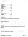
TABLE OF CONTENTS
page
Introduction ........................................................................................... A-2
Cautions and Warnings ........................................................................ A-3
Know Your Machine .....................................................................A-4 – A-5
Control Panel ........................................................................................ A-6
Prepare the Machine for Use
Install the Batteries ............................................................................... A-7
Install the Brushes .......................................................................A-8 – A-9
Fill the Solution Tank .......................................................................... A-10
Squeegee Installation ......................................................................... A-11
Detergent System ....................................................................A-12 – A-13
Operating the Machine ............................................................A-14 – A-15
Scrubbing ................................................................................A-14 – A-15
Wet Vacuuming .......................................................................A-14 – A-15
After Use ............................................................................................. A-16
Maintenance Schedule ....................................................................... A-16
Lubricating the Machine ..........................................................A-16 – A-17
Charging the Batteries ........................................................................ A-18
Check the Battery Water Level ...........................................................A-18
Squeegee Maintenance ...................................................................... A-19
Squeegee Adjustment ........................................................................ A-19
Side Skirt Maintenance ............................................................A-20 – A-21
Side Broom Maintenance ...................................................................A-22
Troubleshooting .................................................................................. A-23
Technical Specifi cations .....................................................................A-24
INTRODUCTION
This manual will help you get the most from your Nilfi sk Rider Scrubber. Read it thoroughly before operating the machine.
Note: Bold numbers in parentheses indicate an item illustrated on pages A-4 – A-6.
This product is intended for commercial use only.
PARTS AND SERVICE
Repairs, when required, should be performed by your Authorized Nilfi sk Service Center, who employs factory trained service personnel, and maintains an inventory
of Nilfi sk original replacement parts and accessories.
Call the NILFISK DEALER named below for repair parts or service. Please specify the Model and Serial Number when discussing your machine.
MODIFICATIONS
Modifi cations and additions to the cleaning machine which affect capacity and safe operation shall not be performed by the customer or user without prior written
approval from Nilfi sk-Advance Inc. Unapproved modifi cations will void the machine warranty and make the customer liable for any resulting accidents.
NAME PLATE
The Model Number and Serial Number of your machine are shown on the Nameplate on the machine. This information is needed when ordering repair parts for
the machine. Use the space below to note the Model Number and Serial Number of your machine for future reference.
MODEL NUMBER _______________________________________________________
SERIAL NUMBER ______________________________________________________
UNCRATE THE MACHINE
When the machine is delivered, carefully inspect the shipping packaging and the machine for damage. If damage is evident, save the shipping carton (if
applicable) so that it can be inspected. Contact the Nilfi sk Customer Service Department immediately to fi le a freight damage claim. Refer to the unpacking
instruction sheet included with the machine to remove the machine from the pallet.
revised 6/11

ENGLISH / A-3
FORM NO. 56041978 - BR1100S / BR1300S - A-3
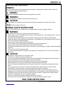
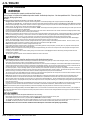
CAUTIONS AND WARNINGS
SYMBOLS
Nilfi sk uses the symbols below to signal potentially dangerous conditions. Always read this information carefully and take the
necessary steps to protect personnel and property.
DANGER!
Is used to warn of immediate hazards that will cause severe personal injury or death.
WARNING!
Is used to call attention to a situation that could cause severe personal injury.
CAUTION!
Is used to call attention to a situation that could cause minor personal injury or damage to the machine or other property.
Read all instructions before using.
GENERAL SAFETY INSTRUCTIONS
Specifi c Cautions and Warnings are included to warn you of potential danger of machine damage or bodily harm.
WARNING!
• This machine shall be used only by properly trained and authorized persons.
• While on ramps or inclines, avoid sudden stops when loaded. Avoid abrupt sharp turns. Use low speed down hills. Clean only
while ascending (driving up) the ramp.
• Keep sparks, fl ame and smoking materials away from batteries. Explosive gases are vented during normal operation.
• Charging the batteries produces highly explosive hydrogen gas. Charge batteries only in well-ventilated areas, away from open
fl ame. Do not smoke while charging the batteries.
• Remove all jewelry when working near electrical components.
• Turn the key switch off (O) and disconnect the batteries before servicing electrical components.
• Never work under a machine without safety blocks or stands to support the machine.
• Do not dispense fl ammable cleaning agents, operate the machine on or near these agents, or operate in areas where fl ammable
liquids exist.
• Do not clean this machine with a pressure washer.
• Only use the brushes provided with the appliance or those specifi ed in the instruction manual. The use of other brushes may
impair safety.
CAUTION!
• This machine is not approved for use on public paths or roads.
• This machine is not suitable for picking up hazardous dust.
• Do not use scarifi er discs and grinding stones. Nilfi sk will not be held responsible for any damage to fl oor surfaces caused by
scarifi ers or grinding stones (can also cause damage to the brush drive system).
• When operating this machine, ensure that third parties, particularly children, are not endangered.
• Before performing any service function, carefully read all instructions pertaining to that function.
• Do not leave the machine unattended without fi rst turning the key switch off (O), removing the key and applying the parking
brake.
• Turn the key switch off (O) and remove the key, before changing the brushes, and before opening any access panels.
• Take precautions to prevent hair, jewelry, or loose clothing from becoming caught in moving parts.
• Use caution when moving this machine in below freezing temperature conditions. Any water in the solution, recovery or
detergent tanks or in the hose lines could freeze, causing damage to valves and fi ttings. Flush with windshield washer fl uid.
• The batteries must be removed from the machine before the machine is scrapped. The disposal of the batteries should be
safely done in accordance with your local environmental regulations.
• Do not use on surfaces having a gradient exceeding that marked on the machine.
• All doors and covers are to be positioned as indicated in the instruction manual before using the machine.
SAVE THESE INSTRUCTIONS

A-4 / ENGLISH
A-4 - FORM NO. 56041978 - BR1100S / BR1300S
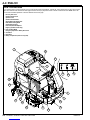
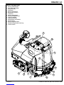
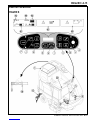
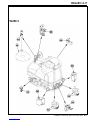
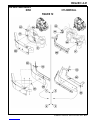
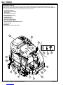
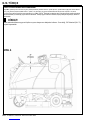
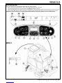
KNOW YOUR MACHINE
As you read this manual, you will occasionally run across a bold number or letter in parentheses - example: (2). These numbers refer to an item shown on these
pages unless otherwise noted. Refer back to these pages whenever necessary to pinpoint the location of an item mentioned in the text. NOTE: Refer to the
service manual for detailed explanations of each item illustrated on the next 3 pages.
1 Recovery Tank Cover
2 Solution Tank Fill Cover
3 Operator’s Seat
4 Solution Tank Drain Hose
5 Steering Wheel Tilt Adjust Knob
6 Brake Pedal / Parking Brake
7 Solution Shut off Valve
8 Drive Pedal, Directional/Speed
9 Hopper (cylindrical models only)
10 Drive and Steer Wheel
11 Emergency Stop Switch / Battery Disconnect
12 Scrub Deck
13 Rear Wheel
14 Battery Compartment (under recovery tank)
1
2
5
6
8
10
11
12
13
14
20
21
3
24 25 26
27
29
23
30
revised 6/11

ENGLISH / A-5
FORM NO. 56041978 - BR1100S / BR1300S - A-5
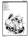
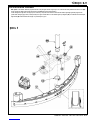
KNOW YOUR MACHINE
15 Recovery Tank Shutoff Float
16 Vacuum Motor Filter Housing
17 Squeegee Assembly
18 Solution Filter
19 Recovery Tank Drain Hose
20 Machine Battery Connector
21 Control Panel
22 Squeegee Tilt Adjust Knob
23 Operator Seat Adjustment Lever
24 Control Circuit Breaker
25 Auxiliary Circuit Breaker
26 Side Broom Motor Circuit Breaker
27 Side Access Panel
28 Squeegee Height Adjust Knob
29 Detergent Cartridge (EcoFlex models only)
30 Tie Down Locations
4
9
15
16
17
18
19
22
7
28
28
30
revised 6/11

A-6 / ENGLISH
A-6 - FORM NO. 56041978 - BR1100S / BR1300S
0.2
!
!
K
K1
K2
K3 K4 K5
K6
K7
K8
K
0.3%
K9
A
B
C
D
E
G
H
FJ
K
IL
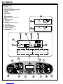
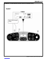
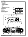
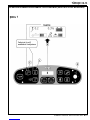
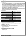
CONTROL PANEL
A Key Switch
B Traction Control Switch
C Side Broom Switch (cylindrical models only)
D Scrub ON / Scrub Mode Select
E Scrub OFF
F Solution Switch
G EcoFlex™ Switch
H Horn
I Vacuum / Wand Switch
J Detergent System (EcoFlex models only)
K Display
K1 Solution Flow Indicator
K2 Fault Indicator
K3 Hour Meter
K4 Detergent Indicator (if so equipped)
K5 Battery Indicator
K6 Scrub Pressure Indicator
K7 Recovery Tank FULL Indicator
K8 Battery Low Indicator
K9 Detergent Percentage Indicator
L Scrub Speed Switch
Flow Flow Flow Regular Heavy Extreme
Rate 1 Rate 2 Rate 3 Scrub Scrub Scrub
(regular scrub) (heavy scrub) (extreme scrub) (press 1 time) (press 2 times) (press 3 times)

ENGLISH / A-7
FORM NO. 56041978 - BR1100S / BR1300S - A-7
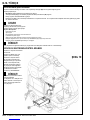
INSTALL THE BATTERIES
WARNING!
Use extreme caution when working with batteries. Sulfuric acid in batteries can cause severe injury if allowed to contact the skin
or eyes. Explosive hydrogen gas is vented from the batteries through openings in the battery caps. This gas can be ignited by
any electrical arc, spark or fl ame. Do not install any lead-acid battery in a sealed container or enclosure. Hydrogen gas from
overcharging must be allowed to escape.
When Servicing Batteries...
* Remove all jewelry
* Do not smoke
* Wear safety glasses, rubber gloves and a rubber apron
* Work in a well-ventilated area
* Do not allow tools to touch more than one battery terminal at a time
* ALWAYS disconnect the negative (ground) cable fi rst when replacing batteries to prevent sparks.
* ALWAYS connect the negative cable last when installing batteries.
CAUTION!
Electrical components in this machine can be severely damaged if the batteries are not installed and connected properly. Batteries
should be installed by Nilfi sk or by a qualifi ed electrician.
1 Remove the batteries from their shipping crate and carefully inspect them for cracks or other damage. If damage is evident, contact the carrier that delivered
them or the battery manufacturer to fi le a damage claim.
2 Turn the Master Key Switch (A) OFF and remove the key.
3 Remove the recovery tank from the machine. NOTE: Disconnect the tether and the vacuum motor wiring and lift the tank straight up and off the machine.
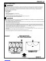
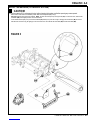
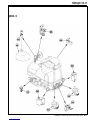
4 Your machine comes from the factory with enough battery cables to install six 6 volt batteries. Using at least (2) people and an appropriate lifting strap,
carefully lift the batteries into the battery compartment and arrange them exactly as shown in FIGURE 1. Secure the batteries as close to the front of the
machine as possible. If installing a mono-block battery use an overhead hoist.
5 Install the battery cables as shown. Position the cables so the battery caps can be easily removed for battery service.
6 Carefully tighten the nut in each battery terminal until the terminal will not turn. Do not over-tighten the terminals, or they will be very diffi cult to remove for
future service.
7 Coat the terminals with spray-on battery terminal coating (available at most auto parts stores).
8 Put one of the black rubber boots over each of the terminals and connect the Battery Pack Connector (20).
FIGURE 1

A-8 / ENGLISH
A-8 - FORM NO. 56041978 - BR1100S / BR1300S
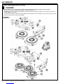
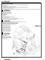
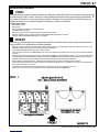
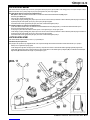
INSTALL THE BRUSHES (DISC SYSTEM)
CAUTION!
Turn the key switch off (O) and remove the key, before changing the brushes, and before opening any access panels.
1 Make sure the Scrub Deck is in the RAISED position. Make sure the Key Switch (A) is off (O).
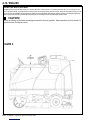
2 See Figure 2. Remove both side skirt assemblies. NOTE: The skirts are held in place by two large Knobs (AA). Loosen these knobs and slide the Skirt
Assemblies (BB) off of the Scrub Deck.
3 To mount the Brushes (CC) (or pad holders) align the Lugs (DD) on the brush with the holes on the mounting plate and turn to lock in place (turn the outside
edge of brush towards the front of machine as shown (EE)).
FIGURE 2

ENGLISH / A-9
FORM NO. 56041978 - BR1100S / BR1300S - A-9
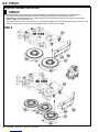
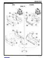
INSTALL THE BRUSHES (CYLINDRICAL SYSTEM)
CAUTION!
Turn the key switch off (O) and remove the key, before changing the brushes, and before opening any access panels.
1 Make sure the Scrub Deck is in the RAISED position. Make sure the Key Switch (A) is off (O).
2 See Figure 3. Remove both side skirt assemblies. NOTE: The skirts are held in place by two large Knobs (AA). Loosen these knobs, slide the Skirt
Assemblies (BB) forward slightly and then off of the Scrub Deck.
3 Loosen the Black Knobs (CC) on top of the Idler Assemblies (DD) until they drop down far enough to disengage from the Notches (EE) and remove.
4 Slide the brush into the housing, lift slightly, push and turn until it seats. Re-install the Idler Assemblies (DD) and Skirt Assemblies (BB).
FIGURE 3

A-10 / ENGLISH
A-10 - FORM NO. 56041978 - BR1100S / BR1300S
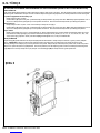
FILLING THE SOLUTION TANK
See Figure 4. Fill the solution tank with a maximum of 70 gallons (264 Liters) of cleaning solution. Do not fi ll the solution tank above 7.5 cm (3 inches) from the
bottom of the Solution Fill (2). The solution should be a mixture of water and the proper cleaning chemical for the job. Always follow the dilution instructions on the
chemical container label. NOTE: EcoFlex machines can either be used conventionally with detergent mixed in the tank or the detergent dispensing
system can be used. When using the detergent dispensing do not mix detergent in the tank, plain water should be used.
CAUTION!
Use only low-foaming, non-fl ammable liquid detergents intended for machine application. Water temperature should not exceed 130
degrees fahrenheit (54.4 degrees celsius)
FIGURE 4

ENGLISH / A-11
FORM NO. 56041978 - BR1100S / BR1300S - A-11
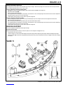
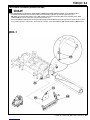
SQUEEGEE INSTALLATION
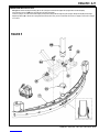
1 See Figure 5. Slide the Squeegee Assembly (17) onto the squeegee mount bracket and tighten the Squeegee Mount Thumb Nuts (AA).
2 Connect the Recovery Hose (BB) to the squeegee inlet using Hose Clamp (CC).
3 Lower the squeegee, move the machine ahead slightly and adjust the squeegee tilt and height using the Squeegee Tilt Adjust Knob (22) and Squeegee
Height Adjust Knobs (28) so that the rear squeegee blade touches the fl oor evenly across its entire width and is bent over slightly as shown in the squeegee
cross section.
FIGURE 5

A-12 / ENGLISH
A-12 - FORM NO. 56041978 - BR1100S / BR1300S
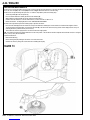
DETERGENT SYSTEM PREPARATION AND USE (ECOFLEX MODELS ONLY)
COMMON INSTRUCTIONS:
Pressing and releasing the Detergent Switch (J) while the solution system is active will cause the detergent system to alternately turn on and off. The system
should be purged of previous detergent when switching to a different detergent. SERVICE NOTE: Move machine over fl oor drain before purging because a small
amount of detergent will be dispensed in the process.
To Purge When Changing Chemicals:
1 Disconnect and remove the detergent cartridge.
2 Turn the Key Switch (A) ON. Press and hold the Solution Switch (F) and the Detergent Switch (J) down for 3 seconds. NOTE: Once activated the purge
process takes 10 seconds. See illustration on next page for Detergent System indicators. Normally one purge cycle is adequate to purge the system.
To Purge Weekly:
1 Disconnect and remove the detergent cartridge. Install and connect a Cartridge fi lled with clean water.
2 Turn the Key Switch (A) ON. Press and hold Solution Switch (F) and the Detergent Switch (J) down for 3 seconds. NOTE: Once activated the purge
process takes 10 seconds. See illustration on next page for Detergent System indicators. Normally one purge cycle is adequate to purge the system.
Detergent Percentage:
1 The detergent percentage default is 0.25%. To change the percentage, the detergent system must be OFF, then press and hold the Detergent ON/OFF
Switch (J) for 2 seconds. The detergent indicator will fl ash and each press of the switch will cycle through the available percentages (3%, 2%, 1.5%, 1%,
0.8%, 0.66%, 0.5%, 0.4%, 0.3%., 0.25%). Once the desired percentage is displayed on the screen (K9), stop and it will lock in after 5 seconds.
CARTRIDGE INSTRUCTIONS:
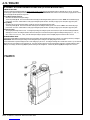
The Detergent Cartridge (29) is located behind the Side Access Panel (27). Fill the detergent cartridge with a maximum of 2.2 gallons (8.32 Liters) of detergent.
SERVICE NOTE: Remove the detergent cartridge from the detergent box prior to fi lling to avoid spilling detergent on the machine.
It is recommended that a separate cartridge be used for each detergent you plan to use. The detergent cartridges have a white decal on them so you can write the
detergent name on each cartridge to avoid mixing them up. The system should be purged of previous detergent when switching to a different detergent. When
installing a new cartridge, remove the Cap (AA) and place the cartridge in the detergent box. Install the Dry Break Cap (BB) and detergent hose as shown.
FIGURE 6


A-14 / ENGLISH
A-14 - FORM NO. 56041978 - BR1100S / BR1300S
OPERATING THE MACHINE
WARNING!
Be sure you understand the operator controls and their functions.
While on ramps or inclines, avoid sudden stops when loaded. Avoid abrupt sharp turns. Use low speed down hills. Clean only while
ascending (driving up) the ramp.
To Scrub...
Follow the instructions in preparing the machine for use section of this manual.
1 See Figure 8. While seated on the machine, adjust the seat and steering wheel to a comfortable operating position using the adjustment controls (23) and (5).
2 Turn the Master Key Switch (A) ON (I). This will display the control panel indicator lights. Reference the Battery Condition Indicator (K5) and Hour Meter (K3) before proceeding.
3 Release the Parking Brake (6). To transport the machine to the work area, apply even pressure with your foot on the front of the Drive Pedal (8) to go forward or the rear of the
pedal for reverse. Vary the pressure on the foot pedal to obtain the desired speed.
4 Press the Solution Switch (F) and hold for 5 seconds to pre-wet the fl oor. NOTE: This will help prevent scarring of the fl oor surface when starting to scrub with dry brushes. This
must be done prior to pressing the Scrub ON Switch (D).
5 Press the Scrub ON Switch (D) once for Regular Scrub, twice for Heavy Scrub or three times for Extreme Scrub mode. Both the solution fl ow and detergent (EcoFlex models)
fl ow have 3 presets that coincide with the 3 scrub modes (see Control Panel).
NOTE: There is a solution fl ow rate override function if you wish to increase solution fl ow without increasing scrub pressure. Hold the Solution Switch (F) for 3 seconds (solution
indicator will start fl ashing) and then let go. You then have 3 seconds to set a different fl ow rate by simply pressing the Solution Switch (F) repeatedly until the Solution Flow
Indicator (K1) shows the rate you desire (1-5 / see Control Panel). Any subsequent scrub pressure adjustments will reset the solution fl ow rate to default.
NOTE: The scrub, solution, vacuum, detergent (EcoFlex models) and side broom (cylindrical models) systems are automatically enabled when the Scrub ON Switch (D) is
pressed. Any individual system can be turned OFF or back ON by simply pressing its switch at any time during scrubbing.
6 When the Scrub ON Switch (D) is selected, the brushes, squeegee and side brooms (cylindrical models) are automatically lowered to the fl oor. The scrub, solution, vacuum,
detergent (EcoFlex models) and side broom (cylindrical models) systems all start when the Drive Pedal (8) is activated.
NOTE: When operating the machine in reverse the squeegee automatically raises.
7 Begin scrubbing by driving the machine forward in a straight line at a normal walking speed and overlap each path by 2-3 inches (50-75 mm). Adjust the machine speed and
solution fl ow when necessary according to the condition of the fl oor.
NOTE: The maximum scrub speed can be increased by pressing the Scrub Speed Switch (L). The normal max scrub speed is 80% of transport speed. Pressing this switch
increases it to 100% of transport speed.
If scrubbing on a smooth fl oor surface or double-scrubbing turning on the Traction Control™ button (B) regulates the drive wheel torque providing increased control and
enhanced traction on the fl oor.
The side broom height can be adjusted. See the “Side Broom Maintenance” section of this manual.
CAUTION!
To avoid damaging the fl oor, keep the machine moving while the brushes are turning.
8 When scrubbing, check behind the machine occasionally to see that all of the waste water is being picked up. If there is water trailing the machine, you may be dispensing too
much solution, the recovery tank may be full, or the squeegee tool may require adjustment.
9 The machine defaults to the EcoFlex cleaning mode (EcoFlex Switch Indicator is lit) conserving solution and detergent. Press the EcoFlex Switch (G) to override the EcoFlex
cleaning mode and temporarily increase scrub pressure, solution fl ow and the detergent percentage. This will cause the indicator to fl ash for one minute, solution fl ow rate will
increase to the next level, scrub pressure will increase to the next level and the detergent percentage will increase to the next larger percentage.
10 For extremely dirty fl oors, a one-pass scrubbing operation may not be satisfactory and a “double-scrub” operation may be required. This operation is the same as a one-pass
scrubbing except on the fi rst pass the squeegee is in the up position (press the Vacuum/Wand Switch (I) to raise the squeegee). This allows the cleaning solution to remain on
the fl oor to work longer. The fi nal pass is made over the same area, with the squeegee lowered to pick up the accumulated solution.
11 The recovery tank has a shut-off fl oat (15) that causes ALL systems to turn OFF except the drive system when the recovery tank is full. When this fl oat is activated, the recovery
tank must be emptied. The machine will not pick up water or scrub with the fl oat activated.
NOTE: All other indicators vanish and a “Recovery Tank FULL” Indicator (K7) appears on the Display Panel when the fl oat is activated. If the control repeatedly gives a full
indication when the tank is not full, the automatic shut-off feature can be disabled, have a qualifi ed service technician refer to the service manual to perform this function.
12 When the operator wants to stop scrubbing or the recovery tank is full, press the Scrub OFF Switch (E) once. This will automatically stop the scrub brushes and solution fl ow and
the scrub deck will raise up. The squeegee will raise up after a brief delay and the vacuum will stop after a brief delay (this is to allow any remaining water to be picked up without
turning the vacuum back on).
13 Drive the machine to a designated waste water “DISPOSAL SITE” and empty the recovery tank. To empty, pull the Drain Hose (19) from its rear storage area, then remove the
plug (hold the end of the hose above the water level in the tank to avoid sudden, uncontrolled fl ow of waste water). Refi ll the solution tank and continue scrubbing.
NOTE: Make sure the Recovery Tank Cover (1) and the Recovery Tank Drain Hose (19) cap are properly seated or the machine will not pick-up water correctly.
When the batteries require recharging the Battery LOW Indicator (K8) will come on, the scrub brushes and solution fl ow will stop and the scrub deck will raise up. The squeegee will
raise up after a brief delay and the vacuum will stop after a brief delay. Transport the machine to a service area and recharge the batteries according to the instructions in the Battery
section of this manual.
WET VACUUMING
Steps to follow in fi tting the machine with optional attachments for wet vacuuming.
1 Disconnect the recovery hose from the squeegee (17). Connect the coupler and hose from the wand kit to the recovery hose.
2 Attach suitable wet pick-up tools to the hose. (An optional Wand Kit PN56413687 is available from Nilfi sk).
3 Turn the Master Key Switch (A) ON and press the Vacuum/Wand Switch (I). The vacuum motor and the pump will run continuously until the switch is pressed again to turn it
OFF. NOTE: The “Recovery Tank FULL” indicator is disabled when the wand mode is activated. The fl oat will stop the fl ow into the recovery tank.
SERVICE NOTE: Refer to the service manual for detailed functional descriptions of all controls and optional programmability.


A-16 / ENGLISH
A-16 - FORM NO. 56041978 - BR1100S / BR1300S
AFTER USE
1 When fi nished scrubbing, press the Scrub Off Switch (E). This will automatically raise, retract and stop all the machine systems (brush, squeegee, vacuum,
solution and detergent (EcoFlex models)). Then drive the machine to a service area for daily maintenance and review of other needed service up keep.
2 To empty the solution tank, remove the Solution Drain Hose (4) from it’s storage clamp. Direct the hose to a designated “DISPOSAL SITE” and remove the
plug. Rinse the tank with clean water.
3 To empty the recovery tank, pull the Recovery Tank Drain Hose (19) from its storage area. Direct the hose to a designated “DISPOSAL SITE” and remove
the plug (hold the end of the hose above the water level in the tank to avoid sudden, uncontrolled fl ow of waste water). The Recovery Tank Drain Hose can
be squeezed to regulate the fl ow. Rinse the recovery tank with clean water. Inspect the recovery and vacuum hoses; replace if kinked or damaged.
4 Remove the brushes or pad holders. Rinse the brushes or pads in warm water and hang up to dry.
5 Remove the squeegee, rinse it with warm water and re-install on mount.
6 Remove the hopper on cylindrical systems and clean thoroughly. Remove from either side of the machine by removing the skirt and tilting the hopper up and
away from housing, then pull out.
7 Check the maintenance schedule below and perform any required maintenance before storage
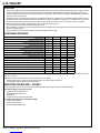
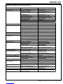
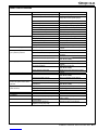
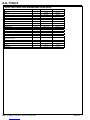
MAINTENANCE SCHEDULE
MAINTENANCE ITEM Daily Weekly Monthly Yearly
Charge Batteries X
Check/Clean Tanks & Hoses X
Check/Clean/Rotate the Brushes/Pads X
Check/Clean the Squeegee X
Check/Clean Vacuum Shut-Off Float X
Check/Clean the vacuum motor foam fi lter(s) X
Clean Hopper on Cylindrical System X
Check Each Battery Cell(s) Water Level X
Inspect Scrub Housing Skirts X
Inspect and clean Solution Filter X
Check Foot/ Parking Brake For Wear & Adjustment X
Clean Solution Trough on Cylindrical System X
Purge Detergent System (EcoFlex only) X
Side Broom Maintenance X
Lubrication - Grease Fittings X
* Check Carbon Brushes X
* Have Nilfi sk check the vacuum motor carbon motor brushes once a year or after 300 operating hours. The brush and drive motor carbon brushes check every
500 hours or once a year.
NOTE: Refer to the Service Manual for more detail on maintenance and service repairs.
8 Store the machine indoors in a clean dry place. Keep from freezing. Leave the tanks open to air them out.
9 Turn the Master Key Switch (A) OFF (O) and remove the key.
LUBRICATING THE MACHINE – FIGURE 9
Once a month, pump a small amount of grease into each grease fi tting on the machine until grease seeps out around the bearings.
Grease fi tting locations (or apply grease to) (AA):
• Squeegee Caster Wheel Axle and Pivot
• Steering Wheel Shaft Universal joint
• Steering Chain
• Squeegee mount angle adjustment knob threads
Once a month, apply light machine oil to lubricate the (BB):
• Squeegee tool end wheels
• Recovery Tank release latch
• Brake Pedal (parking brake) linkage


A-18 / ENGLISH
A-18 - FORM NO. 56041978 - BR1100S / BR1300S
CHARGING THE BATTERIES
Charge the batteries each time the machine is used or when the Battery Indicator (K5) is reading less than full.
To Charge the Batteries...
1 See Figure 10. Depress the Battery Disconnect (11).
2 Open Side Access Panel (27) and push the connector from the charger into the Battery Connector (20).
3 Follow the instructions on the battery charger.
4 After charging the batteries check the fl uid level in all battery cells. Add distilled water, if necessary, to bring the fl uid level up to the bottom of the fi ller tubes.
WARNING!
Do not fi ll the batteries before charging.
Charge batteries in a well-ventilated area.
Do not smoke while servicing the batteries.
When Servicing Batteries...
* Remove all jewelry
* Do not smoke
* Wear safety glasses, rubber gloves and a rubber apron
* Work in a well-ventilated area
* Do not allow tools to touch more than one battery terminal at a time
* ALWAYS disconnect the negative (ground) cable fi rst when replacing batteries to prevent sparks.
* ALWAYS connect the negative cable last when installing batteries.
CAUTION!
To avoid damage to fl oor surfaces, wipe water and acid from the top of the batteries after charging.
CHECKING THE BATTERY WATER LEVEL
Check the water level of the batteries at least once a week.
After charging the batteries, remove
the vent caps and check the water
level in each battery cell. Use distilled
or demineralized water in a battery
fi lling dispenser (available at most auto
parts stores) to fi ll each cell to the level
indicator (or to 10 mm over the top of
the separators). DO NOT over-fi ll the
batteries!
CAUTION!
Acid can spill onto the fl oor if the
batteries are overfi lled.
Tighten the vent caps. Wash the tops
of the batteries with a solution of baking
soda and water (2 tablespoons of baking
soda to 1 liter of water).
FIGURE 10

ENGLISH / A-19
FORM NO. 56041978 - BR1100S / BR1300S - A-19
SQUEEGEE MAINTENANCE
If the squeegee leaves narrow streaks or water, the blades may be dirty or damaged. Remove the squeegee, rinse it under warm water and inspect the blades.
Reverse or replace the blades if they are cut, torn, wavy or worn.
To Reverse or Replace the Rear Squeegee Wiping Blade...
1 See Figure 11. Raise the squeegee tool off the fl oor, then unsnap the Center Latch (AA) on the squeegee tool.
2 Remove the Tension Straps (BB).
3 Slip the rear blade off the alignment pins.
4 The squeegee blade has 4 working edges as shown below. Turn the blade so a clean, undamaged edge faces toward the front of the machine. Replace the
blade if all 4 edges are nicked, torn or worn to a large radius.
5 Install the blade, following the steps in reverse order and adjust the squeegee tilt.
To Reverse or Replace the Front Squeegee Blade...
1 Raise the squeegee tool off the fl oor, then loosen the (2) Thumb Nuts (CC) on top of the squeegee and remove the squeegee tool from the mount.
2 Remove both rear Tension Straps fi rst.
3 Remove all the wing nuts that hold the front blade in place, then remove tension strap and blade.
4 The squeegee blade has 4 working edges as shown below. Turn the blade so a clean, undamaged edge faces toward the front of the machine. Replace the
blade if all 4 edges are nicked, torn or worn to a large radius.
5 Install the blade, following the steps in reverse order and adjust the squeegee tilt.
SQUEEGEE ADJUSTMENT
There are two squeegee tool adjustments possible, angle and height.
Adjusting the Squeegee Angle
Adjust the squeegee angle whenever a blade is reversed or replaced, or if the squeegee is not wiping the fl oor dry.
1 Park the machine on a fl at, even surface.
2 Lower the squeegee, move the machine ahead slightly and adjust the squeegee tilt and height using the Squeegee Tilt Adjust Knob (22) and Squeegee
Height Adjust Knobs (28) so that the rear squeegee blade touches the fl oor evenly across its entire width and is bent over slightly as shown in the squeegee
cross section.
FIGURE 11

A-20 / ENGLISH
A-20 - FORM NO. 56041978 - BR1100S / BR1300S
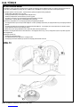
SIDE SKIRT MAINTENANCE
The side skirt’s function is to channel the waste water to the squeegee, helping contain the water within the machines cleaning path. During normal use the blades
will wear in time. The operator will notice a small amount of water leaking out underneath the side skirts. A height adjustment can easily be made to lower the
blades so that all the water can be pick-up by the squeegee.
To reverse or replace the scrub system side skirt(s) ...
1 See Figure 12. Loosen the (2) side skirt Retainer Knobs (AA) (2 per side) and remove the Skirt Assemblies (BB) from the scrub deck. NOTE: Remove the
skirts by fi rst sliding them forward and then pulling them off.
2 Remove all the hardware that holds the blades to the skirt housings. NOTE: The main blade on each skirt housing is held on with Tool-less Retainers. Simply
loosen the large Wing nuts (CC) and then turn the Knobs (DD) on the outside of the skirt housing until they are horizontal and push through the slots. The
small inside Blade (EE) on disk models is held on by (2) screws and nuts and has 2 working edges.
3 The main skirt blade has 4 working edges as shown. Turn the blade so a clean, undamaged edge faces toward the center of the machine. Replace the
blades as a set if all 4 edges are nicked, torn or worn beyond their ability to be adjusted.
4 Reinstall the skirt housing assemblies onto the machine and adjust the blade for proper contact to the fl oor when the brush deck is placed in the scrub
position.
SIDE SKIRT HEIGHT ADJUSTMENT
1 The side skirt housing knob retainer screw studs have leveling Adjuster Collars (FF) that can be raised or lowered to compensate for blade wear.
2 To adjust, remove the Skirt Assemblies (BB) from the scrub deck to access the Adjuster Collars (FF). Adjustment Tip: The skirts Retainer Knobs (AA) can be
loosened with skirts left on and the Adjuster Collars (FF) rotated by reaching under the skirt housing.
3 Turn the Adjuster Collars (FF) (Up or Down) to where the blades just fold over enough when scrubbing that all the waste water is contained inside the skirting.
NOTE: Make small adjustments to obtain good blade wiping. Do not lower the blades too much to where they fold over excessively and cause unneeded
blade wear.
Sayfa yükleniyor...
Sayfa yükleniyor...
Sayfa yükleniyor...
Sayfa yükleniyor...
Sayfa yükleniyor...
Sayfa yükleniyor...
Sayfa yükleniyor...
Sayfa yükleniyor...
Sayfa yükleniyor...
Sayfa yükleniyor...
Sayfa yükleniyor...
Sayfa yükleniyor...
Sayfa yükleniyor...
Sayfa yükleniyor...
Sayfa yükleniyor...
Sayfa yükleniyor...
Sayfa yükleniyor...
Sayfa yükleniyor...
Sayfa yükleniyor...
Sayfa yükleniyor...
Sayfa yükleniyor...
Sayfa yükleniyor...
Sayfa yükleniyor...
Sayfa yükleniyor...
Sayfa yükleniyor...
Sayfa yükleniyor...
Sayfa yükleniyor...
Sayfa yükleniyor...
Sayfa yükleniyor...
Sayfa yükleniyor...
-
 1
1
-
 2
2
-
 3
3
-
 4
4
-
 5
5
-
 6
6
-
 7
7
-
 8
8
-
 9
9
-
 10
10
-
 11
11
-
 12
12
-
 13
13
-
 14
14
-
 15
15
-
 16
16
-
 17
17
-
 18
18
-
 19
19
-
 20
20
-
 21
21
-
 22
22
-
 23
23
-
 24
24
-
 25
25
-
 26
26
-
 27
27
-
 28
28
-
 29
29
-
 30
30
-
 31
31
-
 32
32
-
 33
33
-
 34
34
-
 35
35
-
 36
36
-
 37
37
-
 38
38
-
 39
39
-
 40
40
-
 41
41
-
 42
42
-
 43
43
-
 44
44
-
 45
45
-
 46
46
-
 47
47
-
 48
48
-
 49
49
-
 50
50


Nilfisk-Advance EcoFlex BR 1100 SC Kullanım kılavuzu
- Kategori
- Zemin Makinası
- Tip
- Kullanım kılavuzu
diğer dillerde
İlgili makaleler
Diğer belgeler
-
 Nilfisk-Euroclean CS7000 Instructions For Use Manual
-
Nilfisk-ALTO CR 1500 Kullanım kılavuzu
-
Viper FANG 20HD-EU Kullanım kılavuzu
-
 Comet Spa CPS 65 Kullanım kılavuzu
-
 Comet Spa CRS 66 BXT Kullanım kılavuzu
-
Comet CRS 75/85 BT Kullanım kılavuzu
-
-
-
 Grabo PRO-LIFTER 20 Portable Electric Vacuum Lifting Device Kullanım kılavuzu


