Makita GA4593 Kullanım kılavuzu
- Kategori
- Açılı taşlayıcılar
- Tip
- Kullanım kılavuzu

GA4593
GA4594
GA4595
GA5093
GA5094
GA5095
EN Angle Grinder INSTRUCTION MANUAL 8
FR Meuleuse d’Angle MANUEL D’INSTRUCTIONS 21
DE Winkelschleifer BETRIEBSANLEITUNG 35
IT Smerigliatrice angolare ISTRUZIONI PER L’USO 49
NL Haakse slijpmachine GEBRUIKSAANWIJZING 63
ES Esmeriladora Angular MANUAL DE
INSTRUCCIONES 77
PT Esmerilhadeira Angular MANUAL DE INSTRUÇÕES 91
DA Vinkelsliber BRUGSANVISNING 105
EL 118
TR KULLANMA KILAVUZU 132

2
1
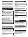
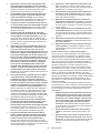
Fig.1
1
Fig.2
1
Fig.3
1
2
Fig.4
Fig.5
1
2
3
Fig.6

3
2
B
1
A
B
Fig.7
2
1
A
C
C
Fig.8
Fig.9
1
2
4
3
Fig.10
1
2
Fig.11
1
2
3
4
Fig.12

4
1
2
3
Fig.13
1
2
4
3
Fig.14
1
Fig.15
12
Fig.16
Fig.17
1
3
2
4
Fig.18
11
44
23
Fig.19
11
44
23
Fig.20

5
1
Fig.21
1
Fig.22
1
Fig.23
1
2
4
5
6
3
Fig.24
Fig.25
1
2
Fig.26
15
Fig.27
Fig.28

6
Fig.29
Fig.30
Fig.31
Fig.32
1
2
2
2
Fig.33

7
22
5
2
2
12
13 14
4
3
5
7
8
9
10
11
1
15
316
17
5
3
18
5
3
20
3
19 21
3
22
5
5
16
17
66
6
6
6
Fig.34

8ENGLISH
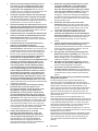
ENGLISH (Original instructions)
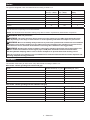
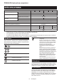
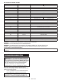
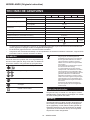
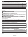
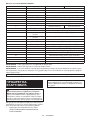
SPECIFICATIONS
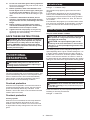
Model: GA4593 GA4594 GA4595 GA5093 GA5094 GA5095
Applicable grinding wheel Max. wheel diameter 115 mm 125 mm
Max. wheel thickness 7.2 mm
Max. wheel diameter 115 mm 125 mm
Max. wheel thickness 3.2 mm
Applicable wire wheel brush Max. wheel diameter 115 mm 125 mm
Max. wheel thickness 20 mm
Spindle thread
Max. spindle length 23 mm
0 11,500 min-1
Overall length 349 mm 326 mm 349 mm 326 mm
Net weight 2.8 - 4.0 kg 2.6 -
3.8 kg
2.9 - 4.0 kg 2.7 -
3.8 kg
/II
without notice.
EPTA-Procedure 01/2014, are shown in the table.
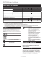
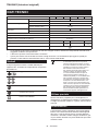
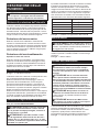
Symbols
meaning before use.
operations.
DOUBLE INSULATION
Due to the presence of hazardous compo-
nents in the equipment, used electrical and
impact on the environment and human
health.
Do not dispose of electrical and electronic
appliances with household waste!
In accordance with the European Directive
on waste electrical and electronic equip-
ment and its adaptation to national law,
used electrical and electronic equipment
delivered to a separate collection point
for municipal waste, operating in accor-
dance with the environmental protection
regulations.
crossed-out wheeled bin placed on the
equipment.
Intended use
The tool is intended for grinding, sanding, wire brush-
ing, hole cutting and cutting of metal and stone materi-
als without the use of water.
Power supply
the same voltage as indicated on the nameplate, and
are double-insulated and can, therefore, also be used
from sockets without earth wire.

9ENGLISH
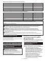
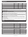
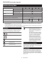
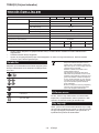
Noise
Model Sound pressure
level (LpA) : (dB(A))
Sound power level
(LWA) : (dB(A))
Uncertainty (K) :
(dB(A))
GA4593 91 99 3
GA4594 91 99 3
GA4595 94 102 3
GA5093 91 99 3
GA5094 91 99 3
GA5095 94 102 3
NOTE:
NOTE:
WARNING: Wear ear protection.
WARNING: -
ue(s) depending on the ways in which the tool is used especially what kind of workpiece is processed.
WARNING: Be sure to identify safety measures to protect the operator that are based on an estimation
of exposure in the actual conditions of use (taking account of all parts of the operating cycle such as the
WARNING: Grinding thin sheets of metal or other easily vibrating structures with a large surface can
result in a total noise emission much higher (up to 15 dB) than the declared noise emission values.
Take the increased noise emission into consideration for both the risk assessment of noise exposure and
selecting adequate hearing protection.
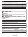
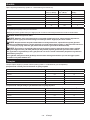
Vibration
Work mode: surface grinding with normal side grip
Model
Vibration emission (ah, AG) : (m/s2)
Uncertainty (K) : (m/s2)
GA4593 5.8 1.5
GA4594 5.8 1.5
GA4595 5.4 1.5
GA5093 8.9 1.5
GA5094 8.9 1.5
GA5095 8.5 1.5
Work mode: surface grinding with anti vibration side grip
Model
Vibration emission (ah, AG) : (m/s2)
Uncertainty (K) : (m/s2)
GA4593 5.7 1.5
GA4594 5.7 1.5
GA4595 5.2 1.5
GA5093 8.5 1.5
GA5094 8.5 1.5
GA5095 8.7 1.5

10 ENGLISH
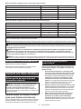
Work mode: disc sanding with normal side grip
Model
Vibration emission (ah, DS) : (m/s2)
Uncertainty (K) : (m/s2)
GA4593 2.6 1.5
GA4594 2.6 1.5
GA4595 2.6 1.5
GA5093 3.3 1.5
GA5094 3.3 1.5
GA5095 3.0 1.5
Work mode: disc sanding with anti vibration side grip
Model
Vibration emission (ah, DS) : (m/s2)
Uncertainty (K) : (m/s2)
GA4593 2.5 m/s2 or less 1.5
GA4594 2.5 m/s2 or less 1.5
GA4595 2.9 1.5
GA5093 3.0 1.5
GA5094 3.0 1.5
GA5095 3.1 1.5
NOTE:
NOTE:
WARNING:
value(s) depending on the ways in which the tool is used especially what kind of workpiece is processed.
WARNING: Be sure to identify safety measures to protect the operator that are based on an estimation
of exposure in the actual conditions of use (taking account of all parts of the operating cycle such as the
WARNING: The declared vibration emission value is used for main applications of the power tool. However if
EC Declaration of Conformity
For European countries only
to this instruction manual.
SAFETY WARNINGS
General power tool safety warnings
WARNING: Read all safety warnings, instruc-
with this power tool. Failure to follow all instructions
Save all warnings and instruc-
tions for future reference.
Grinder safety warnings
Safety warnings common for grinding, sanding,
1. This power tool is intended to function as a
grinder, sander, wire brush, hole cutter or cut-
this power tool. Failure to follow all instructions
2. Operations such as polishing are not to be
performed with this power tool. Operations for
3. Do not convert this power tool to operate in
Such a con-
4. Do not use accessories which are not spe-
manufacturer.
safe operation.
5. The rated speed of the accessory must be at
least equal to the maximum speed marked on
the power tool. Accessories running faster than

11 ENGLISH
6. The outside diameter and the thickness of your
accessory must be within the capacity rating
of your power tool.
7. The dimensions of the accessory mounting
-
ware of the power tool. Accessories that do not
match the mounting hardware of the power tool
8.
Do not use a damaged accessory. Before each use
inspect the accessory such as abrasive wheels for
chips and cracks, backing pad for cracks, tear or
excess wear, wire brush for loose or cracked wires.
If power tool or accessory is dropped, inspect for
damage or install an undamaged accessory. After
inspecting and installing an accessory, position
yourself and bystanders away from the plane of the
rotating accessory and run the power tool at maxi-
mum no-load speed for one minute. Damaged acces-
9. Wear personal protective equipment.
Depending on application, use face shield,
safety goggles or safety glasses. As appro-
priate, wear dust mask, hearing protectors,
gloves and workshop apron capable of stop-
ping small abrasive or workpiece fragments.
The dust mask or respirator must be capable
10.
Keep bystanders a safe distance away from work
area. Anyone entering the work area must wear
personal protective equipment. Fragments of
11.
Hold the power tool by insulated gripping surfaces
only, when performing an operation where the
cutting accessory may contact hidden wiring or its
own cord.
and could give the operator an electric shock.
12. Position the cord clear of the spinning acces-
sory.
13. Never lay the power tool down until the acces-
sory has come to a complete stop. The spinning
14. Do not run the power tool while carrying it at
your side. Accidental contact with the spinning
15. Regularly clean the power tool’s air vents. The
motor’s fan will draw the dust inside the housing
and excessive accumulation of powdered metal
16.
materials. Sparks could ignite these materials.
17. Do not use accessories that require liquid
coolants. Using water or other liquid coolants
Kickback and related warnings:
Kickback is a sudden reaction to a pinched or snagged
-
-
trolled power tool to be forced in the direction opposite
For example, if an abrasive wheel is snagged or
entering into the pinch point can dig into the surface of
the material causing the wheel to climb out or kick out.
operator, depending on direction of the wheel’s move-
break under these conditions.
Kickback is the result of power tool misuse and/or
incorrect operating procedures or conditions and can be
1.
power tool and position your body and arms
to allow you to resist kickback forces. Always
use auxiliary handle, if provided, for maximum
control over kickback or torque reaction during
start-up. The operator can control torque reactions
or kickback forces, if proper precautions are taken.
2. Never place your hand near the rotating acces-
sory.
3. Do not position your body in the area where
power tool will move if kickback occurs.
Kickback will propel the tool in direction opposite
to the wheel’s movement at the point of snagging.
4. Use special care when working corners, sharp
edges, etc. Avoid bouncing and snagging the
accessory.
and cause loss of control or kickback.
5.
Do not attach a saw chain woodcarving blade,
segmented diamond wheel with a peripheral gap
greater than 10 mm or toothed saw blade. Such
blades create frequent kickback and loss of control.
operations:
1.
designed for the selected wheel. Wheels for
which the power tool was not designed cannot be
2. The grinding surface of centre depressed
wheels must be mounted below the plane of
the guard lip.
3. The guard must be securely attached to the
power tool and positioned for maximum safety,
so the least amount of wheel is exposed
towards the operator. The guard helps to protect
the operator from broken wheel fragments, acci-
dental contact with wheel and sparks that could
ignite clothing.
4. -
cations. For example: do not grind with the
are intended for peripheral grinding, side forces
shatter.

12 ENGLISH
5.
correct size and shape for your selected wheel.
6. Do not use worn down wheels from larger
power tools. A wheel intended for larger power
tool is not suitable for the higher speed of a
7. When using dual purpose wheels always use
the correct guard for the application being
performed.
not provide the desired level of guarding, which
operations:
1. -
sive pressure. Do not attempt to make an
excessive depth of cut. Overstressing the wheel
or binding of the wheel in the cut and the possibil-
2. Do not position your body in line with and
behind the rotating wheel. When the wheel, at
-
3. When the wheel is binding or when interrupt-
tool and hold it motionless until the wheel
comes to a complete stop. Never attempt to
the wheel is in motion otherwise kickback may
occur. Investigate and take corrective action to
eliminate the cause of wheel binding.
4.
Do not restart the cutting operation in the work-
piece. Let the wheel reach full speed and carefully
re-enter the cut.
kickback if the power tool is restarted in the workpiece.
5. Support panels or any oversized workpiece to
minimize the risk of wheel pinching and kick-
back. Large workpieces tend to sag under their
own weight. Supports must be placed under the
workpiece near the line of cut and near the edge
of the workpiece on both sides of the wheel.
6. Use extra caution when making a “pocket cut”
into existing walls or other blind areas. The
-
7. Do not attempt to do curved cutting.
Overstressing the wheel increases the loading and
8. Before using a segmented diamond wheel,
make sure that the diamond wheel has the
peripheral gap between segments of 10 mm or
less, only with a negative rake angle.
1. Use proper sized sanding disc paper. Follow
manufacturers recommendations, when
selecting sanding paper. Larger sanding paper
-
tearing of the disc or kickback.
1. Be aware that wire bristles are thrown by the
brush even during ordinary operation. Do not
overstress the wires by applying excessive
load to the brush.
penetrate light clothing and/or skin.
2.
brushing, do not allow any interference of the
wire wheel or brush with the guard. Wire wheel
and centrifugal forces.
Additional Safety Warnings:
1. When using depressed centre grinding wheels,
wheels.
2. NEVER USE Stone Cup type wheels with this
grinder. This grinder is not designed for these
3. Be careful not to damage the spindle, the
lock nut. Damage to these parts could result in
wheel breakage.
4. Make sure the wheel is not contacting the
workpiece before the switch is turned on.
5. Before using the tool on an actual workpiece,
let it run for a while. Watch for vibration or
wobbling that could indicate poor installation
or a poorly balanced wheel.
6. -
form the grinding.
7. Do not leave the tool running. Operate the tool
only when hand-held.
8. Do not touch the workpiece immediately after
operation; it may be extremely hot and could
burn your skin.
9. Do not touch accessories immediately after
operation; it may be extremely hot and could
burn your skin.
10. Observe the instructions of the manufacturer
for correct mounting and use of wheels.
Handle and store wheels with care.
11. Do not use separate reducing bushings or
adaptors to adapt large hole abrasive wheels.
12.
13.
hole wheel, ensure that the thread in the wheel
is long enough to accept the spindle length.
14. Check that the workpiece is properly
supported.
15. Pay attention that the wheel continues to
16. If working place is extremely hot and humid,
or badly polluted by conductive dust, use a
short-circuit breaker (30 mA) to assure opera-
tor safety.
17. Do not use the tool on any materials contain-
ing asbestos.
18.
the dust collecting wheel guard if required by
domestic regulation.
19. Cutting discs must not be subjected to any
lateral pressure.

13 ENGLISH
20. Do not use cloth work gloves during operation.
causes tool breakage.
21. Before operation, make sure that there is no
buried object such as electric pipe, water pipe
or gas pipe in the workpiece.
cause an electric shock, electrical leakage or gas
leak.
22. If a blotter is attached to the wheel, do not
remove it. The diameter of the blotter must be
23. Before installing a grinding wheel, always
check that the blotter part does not have any
abnormalities such as chips or cracks.
24. Tighten the lock nut properly. Overtightening
SAVE THESE INSTRUCTIONS.
WARNING: DO NOT let comfort or familiarity
with product (gained from repeated use) replace
strict adherence to safety rules for the subject
product. MISUSE or failure to follow the safety
rules stated in this instruction manual may cause
serious personal injury.
FUNCTIONAL
DESCRIPTION
CAUTION: Always be sure that the tool is
checking function on the tool.
Tool protection system
reduce power or stop during operation if the tool is
Overload protection
When the tool is operated in a manner that causes it
situation, remove the cause of the overload so that the
rotation speed recovered.
Overheat protection
When the tool is overheated, the tool stops automat-
situation, let the tool cool down. You can turn the tool
on again after the lamp changes the color from red to
green.
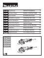
Indication lamp
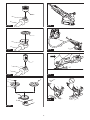
Fig.1: 1. Indication lamp
The indication lamp lights up green when the tool is
plugged.
If the indication lamp blinks in red, the overheat pro-
accidental re-start preventive function stops operation.
on to restart.
tool, the tool is overheated. In this situation, cool down
the tool and wait until the indication lamp lights up in
green.
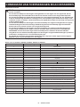
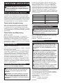
Speed adjusting dial
Only for model GA4593 / GA5093
CAUTION: If the tool is operated continuously
at low speeds for a long time, the motor will get
overloaded and heated up.
CAUTION: The speed adjusting dial can be
turned only as far as 5 and back to 1. Do not force
it past 5 or 1, or the speed adjusting function may
no longer work.
5. Higher speed is obtained when the dial is turned in
the direction of number 5. And lower speed is obtained
the below table for the relationship between the number
settings on the dial and the approximate rotating speed.
Number Rated speed
12,800 min-1
24,500 min-1
36,500 min-1
48,000 min-1
511,500 min-1
Fig.2: 1.
Shaft lock
WARNING: Never actuate the shaft lock when
the spindle is moving.
the tool damage.
Press the shaft lock to prevent spindle rotation when
installing or removing accessories.
Fig.3: 1. Shaft lock

14 ENGLISH
Switch action
CAUTION:
Before plugging in the tool, always
check to see that the switch lever actuates properly
and returns to the "OFF" position when released.
CAUTION:
For your safety, this tool is equipped
-
tended starting. NEVER use the tool if it runs when
you simply pull the switch lever without pulling the
-
vice center for proper repairs BEFORE further usage.
CAUTION: Do not pull the switch lever hard
This can cause
switch breakage.
CAUTION: NEVER tape down or defeat pur-
-
tor and then pull the switch lever.
To stop the tool, release the switch lever.
Fig.4: 1.2. Switch lever
Electronic function
Active Feedback sensing Technology
CAUTION: -
tion stops.
At this time, the indication lamp blinks in red and shows
cause of sudden drop in the rotation speed, and then
turn the tool on.
Accidental re-start preventive function
When plugging in the tool while the switch is ON, the
tool does not start.
At this time, the indication lamp blinks in red and shows
that the accidental re-start preventive function works.
Constant speed control
kept constant even under the loaded condition.
Soft start feature
Soft start feature reduces starting reaction.
Mechanical brake
Only for modelGA4593 / GA4594 / GA5093 / GA5094
Mechanical brake is activated after the tool is switched
down with the switch still on.
ASSEMBLY
CAUTION: Always be sure that the tool is
any work on the tool.
Installing side grip (handle)
CAUTION: Always be sure that the side grip is
installed securely before operation.
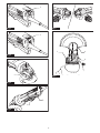
Fig.5
Installing or removing wheel guard
WARNING:
When using a depressed center wheel,
of the guard always points toward the operator.
WARNING: Make sure that the wheel guard is
securely locked by the lock lever with one of the
holes on the wheel guard.
WARNING:
/ diamond wheel, be sure to use only the special
1. While pushing the lock lever, mount the wheel
guard with the protrusions on the wheel guard aligned
with the notches on the bearing box.
Fig.6: 1. Lock lever 2. Notch 3. Protrusion
2.
While pushing the lock lever toward A, hold down
Fig.7: 1. Wheel guard 2. Hole
NOTE: Push down the wheel guard straight.
3.
While pushing the lock lever toward A, rotate the wheel
guard according to the work so that the operator can be pro-
tected. Align the lock lever with one of the holes in the wheel
guard, and then release the lock lever to lock the wheel guard.
Fig.8: 1. Wheel guard 2. Hole
To remove wheel guard, follow the installation proce-
dure in reverse.
Clip-on cutting wheel guard attachment
Optional accessory
NOTE:
wheel guard attachment can be used with the wheel
Not available in some countries.
Fig.9

15 ENGLISH
Installing or removing depressed
Optional accessory
WARNING: When using a depressed center
on the tool so that the closed side of the guard
always points toward the operator.
WARNING: Make sure that the mounting part
result in the dangerous vibration.
the straight part at the bottom of the spindle.
Fig.10: 1. Lock nut 2. Depressed center wheel
3.4. Mounting part
that the spindle cannot revolve, then use the lock nut
Fig.11: 1. Lock nut wrench 2. Shaft lock
To remove the wheel, follow the installation procedure
in reverse.
Optional accessory
WARNING: Always use supplied guard when
Wheel can shatter during
use and guard helps to reduce chances of personal
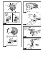
Fig.12: 1. Lock nut 2. Flex wheel 3. Back up pad
4.
Follow instructions for depressed center wheel but also
use back up pad over wheel.
Installing or removing abrasive disc
Optional accessory
Fig.13: 1. Sanding lock nut 2. Abrasive disc
3.
1. Mount the rubber pad onto the spindle.
2. Fit the disc on the rubber pad and screw the sand-
ing lock nut onto the spindle.
3.
tighten the sanding lock nut clockwise with the lock nut
wrench.
To remove the disc, follow the installation procedure in
reverse.
NOTE:-
Optional accessory
Only for model GA4595 / GA5095
NOT equipped with a brake function.
Installing or removing Ezynut
Optional accessory
Only for tools with M14 spindle thread.
CAUTION: Do not use Ezynut with Super
thread cannot be retained by the spindle.
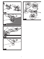
Fig.14: 1.2. Abrasive wheel 3.
4. Spindle
abrasive wheel clockwise as far as it turns.
Fig.15: 1. Shaft lock
counterclockwise.
NOTE:
as the arrow points the notch. Otherwise a lock nut
wrench is required to loosen it. Insert one pin of the
Fig.16: 1. Arrow 2. Notch
Fig.17
wheel
Optional accessory
WARNING:
/ diamond wheel, be sure to use only the special
WARNING:
grinding.
Fig.18: 1. Lock nut 2.-
mond wheel 3.4. Wheel guard
As for the installation, follow the instructions for
depressed center wheel.
The direction for mounting the lock nut and the inner
Fig.19: 1. Lock nut 2.
3. Abrasive cut-
4. Inner
When installing the diamond wheel:
Fig.20: 1. Lock nut 2.
3.
4.

16 ENGLISH
Installing wire cup brush
Optional accessory
CAUTION: Do not use brush that is damaged,
or which is out of balance. Use of damaged brush
broken brush wires.
spindle.
brush onto spindle and tighten with supplied wrench.
Fig.21: 1. Wire cup brush
Installing wire wheel brush
Optional accessory
CAUTION: Do not use wire wheel brush that
is damaged, or which is out of balance. Use of
damaged wire wheel brush could increase potential
CAUTION: ALWAYS use guard with wire
inside guard. Wheel can shatter during use and
spindle.
brush onto spindle and tighten with the wrenches.
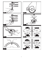
Fig.22: 1. Wire wheel brush
Installing hole cutter
Optional accessory
spindle.
hole cutter onto the spindle, and tighten it with the sup-
plied wrench.
Fig.23: 1. Hole cutter
Installing dust collecting wheel
guard for grinding
Optional accessory
planing concrete surface.
CAUTION: Dust collecting wheel guard for
grinding is only for use in planing concrete sur-
face with a cup-type diamond wheel. Do not use
this guard with any other cutting accessory or for
any other purpose.
CAUTION: Before operation, make sure that
a vacuum cleaner is connected to the tool and
turned on.
Place the tool upside down and install the dust collect-
ing wheel guard.
tighten the lock nut onto the spindle.
Fig.24: 1. Lock nut 2.
3.4. Inner
5. Dust collecting wheel guard
6. Bearing box
NOTE: For information how to install the dust col-
lecting wheel guard, refer to the manual of the dust
collecting wheel guard.
Installing dust collecting wheel
Optional accessory
cutting stone materials.
Fig.25
NOTE: For information how to install the dust col-
lecting wheel guard, refer to the manual of the dust
collecting wheel guard.
Connecting a vacuum cleaner
Optional accessory
WARNING: Never vacuum metal particles
created by grinding/cutting/sanding operation.
cleaner.
-
ting, use a dust collecting wheel guard and a vacuum
cleaner.
collecting wheel guard for assembling and using it.
Fig.26: 1. Dust collecting wheel guard 2. Hose of
the vacuum cleaner
Installing or removing dust cover
attachment
Optional accessory
CAUTION: Always be sure that the tool is
removing the dust cover attachment. Failure to do
position.
For details, refer to the instruction manual of the dust
cover attachment.
NOTICE: Clean out the dust cover attachment
when it is clogged with dust or foreign matters.
attachment will damage the tool.

17 ENGLISH
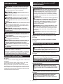
OPERATION
WARNING: It should never be necessary to
force the tool. The weight of the tool applies ade-
quate pressure. Forcing and excessive pressure
could cause dangerous wheel breakage.
WARNING: ALWAYS replace wheel if tool is
dropped while grinding.
WARNING: NEVER hit the workpiece with the
wheel.
WARNING: Avoid bouncing and snagging
the wheel, especially when working corners,
sharp edges etc. This can cause loss of control and
kickback.
WARNING: NEVER use tool with wood cutting
blades and other saw blades. Such blades when
WARNING: Continued use of a worn-out
wheel may result in wheel explosion and serious
personal injury.
CAUTION: Never switch on the tool when it
is in contact with the workpiece, it may cause an
injury to operator.
CAUTION: Always wear safety goggles or a
face shield during operation.
CAUTION:
the tool and wait until the wheel has come to a
complete stop before putting the tool down.
CAUTION:
one hand on housing and the other on the side
grip (handle).
NOTE: A dual purpose wheel can be used for both
operation, and refer to the "Operation with abrasive
Operation with wheel/disc
Fig.27
workpiece.
In general, keep the edge of the wheel or disc at an
angle of about 15° to the workpiece surface.
During the break-in period with a new wheel, do not
the workpiece. Once the edge of the wheel has been
forward and backward direction.
diamond wheel
Optional accessory
WARNING: Do not "jam" the wheel or apply
excessive pressure. Do not attempt to make an
excessive depth of cut. Overstressing the wheel
of kickback, wheel breakage and overheating of the
WARNING: Do not start the cutting operation
in the workpiece. Let the wheel reach full speed
and carefully enter into the cut moving the tool
forward over the workpiece surface. The wheel
started in the workpiece.
WARNING: During cutting operations, never
change the angle of the wheel. Placing side pres-
the wheel to crack and break, causing serious per-
WARNING: A diamond wheel shall be oper-
ated perpendicular to the material being cut.
wheel
Fig.28
Usage example: operation with diamond wheel
Fig.29
Operation with wire cup brush
Optional accessory
CAUTION: Check operation of brush by run-
ning tool with no load, insuring that no one is in
front of or in line with brush.
Usage example: operation with wire cup brush
Fig.30
NOTICE: Avoid applying too much pressure
which causes over bending of wires when using
brush.
Operation with wire wheel brush
Optional accessory
CAUTION: Check operation of wire wheel
brush by running tool with no load, insuring that
no one is in front of or in line with the wire wheel
brush.
Usage example: operation with wire wheel brush
Fig.31
NOTICE: Avoid applying too much pressure
which causes over bending of wires when
using wire wheel brush.
breakage.

18 ENGLISH
Operation with hole cutter
Optional accessory
CAUTION: Check operation of the hole cutter
by running the tool with no load, insuring that no
one is in front of the hole cutter.
NOTICE: Do not tilt the tool during operation. It
Usage example: operation with hole cutter
Fig.32
MAINTENANCE
CAUTION: Always be sure that the tool is
perform inspection or maintenance.
NOTICE: Never use gasoline, benzine, thinner,
alcohol or the like. Discoloration, deformation or
cracks may result.
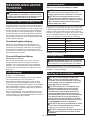
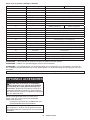
Air vent cleaning
The tool and its air vents have to be kept clean.
vents start to become obstructed.
Fig.33: 1. Exhaust vent 2. Inhalation vent

19 ENGLISH
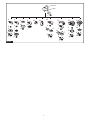
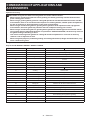
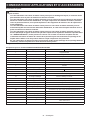
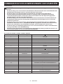
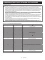
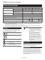
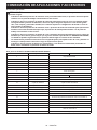
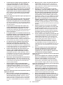
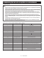
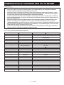
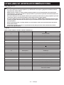
COMBINATION OF APPLICATIONS AND
ACCESSORIES
Optional accessory
CAUTION: Using the tool with incorrect guards can cause risks as follows.
• -
piece causing poor control.
• -
mond wheels, there is an increased risk of exposure to rotating wheels, emitted sparks and particles,
as well as exposure to wheel fragments in the event of wheel burst.
• -
mond wheels, the wheel guard may interfere with the workpiece causing poor control.
• -
the guard leading to breaking of wires.
•
reduces a risk of exposure to dust.
•
Fig.34
Only for model GA4593 / GA4594 / GA5093 / GA5094
-Application
1 - Side grip
2 -
3 -
4Grinding / Sanding Depressed center wheel / Flap disc
5 - Lock nut
6 -
7 - Back up pad
8Grinding / Sanding Flex wheel
9 -
10 Sanding Abrasive disc
11 -Sanding lock nut
12 Wire brushing Wire wheel brush
13 Wire brushing Wire cup brush
14 Hole cutting Hole cutter
15 -
16
17 Dual purpose wheel
18 -
19 -
20 Diamond wheel
21 -Dust collecting wheel guard for grinding
22 Grinding
- - Lock nut wrench
- - Dust cover attachment

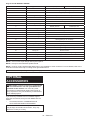
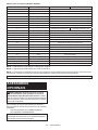
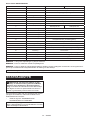
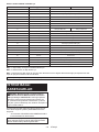
20 ENGLISH
Only for model GA4595 / GA5095
-Application
1 - Side grip
2 -
3 -
4Grinding / Sanding Depressed center wheel / Flap disc
5 - Lock nut
6 -
7 - Back up pad
8Grinding / Sanding Flex wheel
9 -
10 Sanding Abrasive disc
11 -Sanding lock nut
12 Wire brushing Wire wheel brush
13 Wire brushing Wire cup brush
14 Hole cutting Hole cutter
15 -
16
17 Dual purpose wheel
18 -
19 -
20 Diamond wheel
21 -Dust collecting wheel guard for grinding
22 Grinding
- - Lock nut wrench
- - Dust cover attachment
NOTE:
NOTE:
NOTE:
instruction manual of the clip-on cutting wheel guard attachment.
NOTE:
OPTIONAL
ACCESSORIES
CAUTION: These accessories or attachments
are recommended for use with your Makita tool
accessories or attachments might present a risk of
for its stated purpose.
-
NOTE:
Sayfa yükleniyor ...
Sayfa yükleniyor ...
Sayfa yükleniyor ...
Sayfa yükleniyor ...
Sayfa yükleniyor ...
Sayfa yükleniyor ...
Sayfa yükleniyor ...
Sayfa yükleniyor ...
Sayfa yükleniyor ...
Sayfa yükleniyor ...
Sayfa yükleniyor ...
Sayfa yükleniyor ...
Sayfa yükleniyor ...
Sayfa yükleniyor ...
Sayfa yükleniyor ...
Sayfa yükleniyor ...
Sayfa yükleniyor ...
Sayfa yükleniyor ...
Sayfa yükleniyor ...
Sayfa yükleniyor ...
Sayfa yükleniyor ...
Sayfa yükleniyor ...
Sayfa yükleniyor ...
Sayfa yükleniyor ...
Sayfa yükleniyor ...
Sayfa yükleniyor ...
Sayfa yükleniyor ...
Sayfa yükleniyor ...
Sayfa yükleniyor ...
Sayfa yükleniyor ...
Sayfa yükleniyor ...
Sayfa yükleniyor ...
Sayfa yükleniyor ...
Sayfa yükleniyor ...
Sayfa yükleniyor ...
Sayfa yükleniyor ...
Sayfa yükleniyor ...
Sayfa yükleniyor ...
Sayfa yükleniyor ...
Sayfa yükleniyor ...
Sayfa yükleniyor ...
Sayfa yükleniyor ...
Sayfa yükleniyor ...
Sayfa yükleniyor ...
Sayfa yükleniyor ...
Sayfa yükleniyor ...
Sayfa yükleniyor ...
Sayfa yükleniyor ...
Sayfa yükleniyor ...
Sayfa yükleniyor ...
Sayfa yükleniyor ...
Sayfa yükleniyor ...
Sayfa yükleniyor ...
Sayfa yükleniyor ...
Sayfa yükleniyor ...
Sayfa yükleniyor ...
Sayfa yükleniyor ...
Sayfa yükleniyor ...
Sayfa yükleniyor ...
Sayfa yükleniyor ...
Sayfa yükleniyor ...
Sayfa yükleniyor ...
Sayfa yükleniyor ...
Sayfa yükleniyor ...
Sayfa yükleniyor ...
Sayfa yükleniyor ...
Sayfa yükleniyor ...
Sayfa yükleniyor ...
Sayfa yükleniyor ...
Sayfa yükleniyor ...
Sayfa yükleniyor ...
Sayfa yükleniyor ...
Sayfa yükleniyor ...
Sayfa yükleniyor ...
Sayfa yükleniyor ...
Sayfa yükleniyor ...
Sayfa yükleniyor ...
Sayfa yükleniyor ...
Sayfa yükleniyor ...
Sayfa yükleniyor ...
Sayfa yükleniyor ...
Sayfa yükleniyor ...
Sayfa yükleniyor ...
Sayfa yükleniyor ...
Sayfa yükleniyor ...
Sayfa yükleniyor ...
Sayfa yükleniyor ...
Sayfa yükleniyor ...
Sayfa yükleniyor ...
Sayfa yükleniyor ...
Sayfa yükleniyor ...
Sayfa yükleniyor ...
Sayfa yükleniyor ...
Sayfa yükleniyor ...
Sayfa yükleniyor ...
Sayfa yükleniyor ...
Sayfa yükleniyor ...
Sayfa yükleniyor ...
Sayfa yükleniyor ...
Sayfa yükleniyor ...
Sayfa yükleniyor ...
Sayfa yükleniyor ...
Sayfa yükleniyor ...
Sayfa yükleniyor ...
Sayfa yükleniyor ...
Sayfa yükleniyor ...
Sayfa yükleniyor ...
Sayfa yükleniyor ...
Sayfa yükleniyor ...
Sayfa yükleniyor ...
Sayfa yükleniyor ...
Sayfa yükleniyor ...
Sayfa yükleniyor ...
Sayfa yükleniyor ...
Sayfa yükleniyor ...
Sayfa yükleniyor ...
Sayfa yükleniyor ...
Sayfa yükleniyor ...
Sayfa yükleniyor ...
Sayfa yükleniyor ...
Sayfa yükleniyor ...
Sayfa yükleniyor ...
Sayfa yükleniyor ...
Sayfa yükleniyor ...
Sayfa yükleniyor ...
Sayfa yükleniyor ...
Sayfa yükleniyor ...
Sayfa yükleniyor ...
-
 1
1
-
 2
2
-
 3
3
-
 4
4
-
 5
5
-
 6
6
-
 7
7
-
 8
8
-
 9
9
-
 10
10
-
 11
11
-
 12
12
-
 13
13
-
 14
14
-
 15
15
-
 16
16
-
 17
17
-
 18
18
-
 19
19
-
 20
20
-
 21
21
-
 22
22
-
 23
23
-
 24
24
-
 25
25
-
 26
26
-
 27
27
-
 28
28
-
 29
29
-
 30
30
-
 31
31
-
 32
32
-
 33
33
-
 34
34
-
 35
35
-
 36
36
-
 37
37
-
 38
38
-
 39
39
-
 40
40
-
 41
41
-
 42
42
-
 43
43
-
 44
44
-
 45
45
-
 46
46
-
 47
47
-
 48
48
-
 49
49
-
 50
50
-
 51
51
-
 52
52
-
 53
53
-
 54
54
-
 55
55
-
 56
56
-
 57
57
-
 58
58
-
 59
59
-
 60
60
-
 61
61
-
 62
62
-
 63
63
-
 64
64
-
 65
65
-
 66
66
-
 67
67
-
 68
68
-
 69
69
-
 70
70
-
 71
71
-
 72
72
-
 73
73
-
 74
74
-
 75
75
-
 76
76
-
 77
77
-
 78
78
-
 79
79
-
 80
80
-
 81
81
-
 82
82
-
 83
83
-
 84
84
-
 85
85
-
 86
86
-
 87
87
-
 88
88
-
 89
89
-
 90
90
-
 91
91
-
 92
92
-
 93
93
-
 94
94
-
 95
95
-
 96
96
-
 97
97
-
 98
98
-
 99
99
-
 100
100
-
 101
101
-
 102
102
-
 103
103
-
 104
104
-
 105
105
-
 106
106
-
 107
107
-
 108
108
-
 109
109
-
 110
110
-
 111
111
-
 112
112
-
 113
113
-
 114
114
-
 115
115
-
 116
116
-
 117
117
-
 118
118
-
 119
119
-
 120
120
-
 121
121
-
 122
122
-
 123
123
-
 124
124
-
 125
125
-
 126
126
-
 127
127
-
 128
128
-
 129
129
-
 130
130
-
 131
131
-
 132
132
-
 133
133
-
 134
134
-
 135
135
-
 136
136
-
 137
137
-
 138
138
-
 139
139
-
 140
140
-
 141
141
-
 142
142
-
 143
143
-
 144
144
-
 145
145
-
 146
146
-
 147
147
-
 148
148


Makita GA4593 Kullanım kılavuzu
- Kategori
- Açılı taşlayıcılar
- Tip
- Kullanım kılavuzu
Diğer dillerde
- español: Makita GA4593 Manual de usuario
- français: Makita GA4593 Manuel utilisateur
- italiano: Makita GA4593 Manuale utente
- Deutsch: Makita GA4593 Benutzerhandbuch
- português: Makita GA4593 Manual do usuário
- dansk: Makita GA4593 Brugermanual
- Nederlands: Makita GA4593 Handleiding
İlgili Makaleler
Diğer Belgeler
-
Black & Decker KG711 Kullanım kılavuzu
-
Black & Decker KG1202 Kullanım kılavuzu
-
Black & Decker G720R Kullanım kılavuzu
-
Black & Decker G850 Kullanım kılavuzu
-
DeWalt DWE4118 Kullanım kılavuzu
-
-
Stanley STGS9115 Kullanım kılavuzu
-
Stanley SG7125 Kullanım kılavuzu
-
Crown CT13502-100 Kullanım kılavuzu
-
Crown CT13501-115 Kullanım kılavuzu