
Türkçe
Български
Детектор SensoMAG R20 е съвместим с всеки конвенционален пожарен панел с праг на
влизане в състояние ПОЖАР между 10mA и 15mA (между 10mA и 30mA с основа B24RD).
Детектор SensoMAG R20 е съвместим с 4 типа основи:
B B12L/U - Релейна основа (не се покрива от EN 54-5);
C B24 - Стандартна основа, нисък профил; B24-HP - Стандартна основа, висок профил;
ВНИМАНИЕ: Прочетете внимателно инструкцията преди да пристъпите към
инсталиране на детектора!
D B24D - Стандартна основа с Шотки диод;
ВНИМАНИЕ: Изключете захранването на линията преди да монтирате детектора!
6. Ако детекторът е заключен към основата, за да го отворите за почистване и поддръжка
трябва да използвате пластмасовия ключ. Леко натиснете с ключа в отвора на основата и
едновременно с това завъртете детектора обратно на часовниковата стрелка.
7. Тествайте детектора за правилна работа и светлинна индикация.
3. Монтирайте основата на тавана на помещението, като подберете винтове и дюбели според
монтажната повърхност.
4. Извършете електрически монтаж съгласно приложената схема.
5. Поставете детектора в основата и го завъртете по посока на часовниковата стрелка до
попадане в направляващите канали. Продължете да въртите докато маркерите на основата и
детектора съвпаднат - чува се щракване.
ВНИМАНИЕ: В случай, че сте свалили платката на детектора за поддръжка, за да я
монтирате обратно към корпуса, използвайте за ориентир цветния стикер в единия от
ъглите ѝ. Завъртете платката така, че отворът от лявата страна на цветния стикер да
съвпадне с репера от външната страна на корпуса. Отворът трябва да съвпадне с щифта
отдолу. Натиснете внимателно платката надолу, за да я фиксирате на място.
2. Ако желаете да “заключвате” детектора към основата отстранете зъбчето с триъгълна
форма (използвайте малка плоска отвертка) и отчупете пластмасовия ключ. Съхранявайте
пластмасовия ключ на достъпно място, за да можете при необходимост да свалите детектора от
основата.
E B24RD - Стандартна основа с Шотки диод и увеличен ток в алармено състояние.
1. Изберете подходящо място за монтаж на детектора. Следвайте дадените инструкции за
инсталиране. Забележка: Не инсталирайте детектора в близост до естествени източници
на топлина, например над готварски печки, фурни или камини.
Português
O detector SensoMAG R20 é compatível com qualquer central de incêndio convencional com
intervalo de alarme de fogo entre 10mA e 15mA (entre 10mA e 15mA com base B24RD).
B B12L/U - Base com saída de Relé (não cumpre a norma EN 54-5);
O detector SensoMAG R20 pode ser utilizado com 4 tipos diferentes de bases:
ATENÇÃO: Desligar a alimentação antes de instalar o detector!
2. Se desejar “fechar” o detector na base, remova o “dente” em forma de triângulo e quebre a chave
plástica da base. Guarde a chave plástica em local seguro para poder abrir o detector mais tarde.
4. Ligar a base do detector à central de incêndio utilizando o esquema de ligação.
ATENÇÃO: No caso de remover o PCB do detector para Manutenção, quando voltar a colocá-lo
procure a etiqueta colorida no PCB e orientá-la pela marca no corpo em plástico do detector
(visível do exterior). O espaço junto ao ponto colorido tem de coincidir com o pino no corpo em
plástico. Pressione cuidadosamente para fixar o PCB.
1. Escolha o melhor local para a Instalação do detector. Siga as instruções do manual de instalação
fornecido. Nota: Não instale o detector próximo de fontes de calor ex: por cima de fogões, fornos ou
locais com fogo.
C B24 - Base Standard, baixo perfil; B24-HP - Base Standard, alto perfil;
E B24RD - Base Standard com Diodo e aumento da corrente de alarme.
3. Instalar a base do detector no tecto utilizando elementos de fixação apropriados à superficie na
qual se pretende fixar o detector.
5. Introduzir o detector na base e rodar na direcção dos ponteiros do relógio. Continuar a rodar até o
detector estar fechado na base um click é audível.
D B24D - Base Standard com Diodo;
7. Testar o detector e indicação dos LED'S para um funcionamento correcto.
6. Para abrir o detector para Manutenção e limpeza tem de se utilizar uma chave plástica. Pressionar
ligeiramente a chave plastica na base e ao mesmo tempo rodar o detector no sentido oposto ao dos
ponteiros do relógio.
ATENÇÃO: Ler cuidadosamente este manual de instalação antes de instalar o dispositivo!
SensoMAG R20 dedektör yangın rejimi duşük eşik değeri 10mA ÷15mA arası olan her konvansiyonel
panel ile uygundur (değeri 10mA÷15mA B24RD tip soket ile).
B B12L/U - röleli soket (EN 54-5'e göre uyumlu değildir);
C B24 - standart soket, düşük profilli tasarım; B24-HP - standart soket, yüksek profilli tasarım;
SensoMAG R20 dedektör 4 ayrı soket ile kullanılabilir:
E B24RD - standart soket Schottky diod ile ve alarm durumunda artan akım.
DİKKAT: Servis (bakım, onarım) için dedektör kasasını sökmek gerekirse, yeniden takarken
PCB üzerindeki renkli etiketin plastic kasadaki işaretle denk gelmesine ve denk geldiğinde
hafifçe itilerek monte edilmesine dikkat ediniz.
DİKKAT: Montaj yapmadan önce, dikkatle montaj talimatını okuyunuz!
D B24D - standart soket Schottky diod ile;
1.Dedektörün montaj yerini seçiniz. Verilen montaj talimatlarına uyunuz. NOT: Dedektörü ısı
kaynağı yakınına monte etmeyiniz, örneğin ocak, fırın gibi.
3. Dedektör soketini korunan alanın tavanına, uygun vida kullanarak monte ediniz.
2. Dedektör ile soketi birbirine bağlamak istediğinizde, üçgen şeklindeki “dişi” (küçük yassı
tornavida yardımıyla) ayırın ve plastik anahtarı soketten koparın. Plastik anahtarı uygun bir yerde
muhafaza edin. İhtiyaç olduğunda bu anahtar ile dedektörü soketten ayırabilirsiniz.
4. Elektrik bağlantılarını ilgili şemaya göre yapınız.
DİKKAT: Elektrik montajı sırasında besleme olmamalıdır!
5. Dedektörü sokete yerleştiriniz ve saat yönünde, kılavuz kanallara yerleşene kadar çeviriniz.
Çevirmeye devam ediniz. Dedektör ve soket işaretleri karşı karşıya gelecektir ve kilitleme sesi
duyulacaktır.
6. Eğer dedektör soketinden üçgen şeklindeki “dişi” ayırdıysanız, dedektörün temizliği ve bakımı ile
ilgili plastik anahtarı kullanmalısınız. Hafifçe anahtarı soket deliğine bastırınız ve aynı zamanda
dedektörü saat yönüne ters çeviriniz.
7. Dedektörü çalışma ve ışıklı işaretler testine tutunuz.
ATTENTION: Read carefully this installation Instructions before installing the device!
The detector SensoMAG R20 can be used with 4 base types:
The detector SensoMAG R20 is compatible with any conventional Fire Panel with fire alarm threshold
between 10mA and 15mA (between 10mA and 30mA with B24RD fire base).
1. Choose the proper place for installation of the fire detector. Refer to the given installation
instructions. Note: Do not install the detector near to natural heat sources, e.g. above cookers, ovens
or fire places.
B B12L/U - Base with relay output (not covered by EN 54-5);
3. Mount the fire base on the ceiling of the protected premises using fixings according the mounting
surface.
4. Connect the detector base to the fire panel using the wiring diagram.
ATTENTION: Disconnect the line power before installing the detector!
E B24RD - Standard base with Schottky diode and increased alarm state current.
C B24 - Standard base, low profile; B24-HP - Standard base, high profile;
D B24D - Standard base with Schottky diode;
2. If you want to “lock” the detector to the base remove the little “tooth” (with the triangle shape)
and break the plastic key off the base. Keep the plastic key in safe place to be able to open the detector
later.
5. Insert the detector into the base and rotate clockwise until it drops into place. Continue to rotate
the detector until it locks to the base - a click is heard.
6. If the detector has been locked to the base, when opening it for a scheduled maintenance
service and cleaning you have to use the plastic key. Lightly press with the plastic key into the base
opening and at the same time rotate the detector head counter-clockwise.
ATTENTION: In case of removing the detector’s PCB for service maintenance, when mounting
it back, find the colored dot sticker on the PCB and align it to the mark on the plastic body
(visible from the outside). The hole next to the colored dot have to align with the pin on the
plastic body. Gently press downwards to fix the PCB in place.
7. Test the detector for proper operation and LED indication.
English Conventional fire alarm Rate-of-Rise Heat Detector
SensoMAG R20 - Installation Instruction SensoMAG R20 - Инструкция за инсталиране
Конвенционален пожароизвестителен максимално-диференциален
детектор
Detector termovelocimétrico incêndio convencional
SensoMAG R20 - Manual de Instalação SensoMAG R20 - Montaj Kılavuzu
Konvansiyonel sabit sıcaklık dedektörü
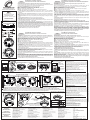
4WIRING DIAGRAM / СХЕМА НА СВЪРЗВАНЕ / ESQUEMA DE LIGAÇÃO / ELEKTRIK TERTIBATI DIYAGRAM
Fire Panel / Пожароизвестителен панел
Central de Incêndio / Yangin kontrol paneli
+ (24V)
(Earth)
RL
RL
56
4. Power off the detector for 2 sec minimum. After resetting the detector
will enter in duty mode and the LEDs will light off.
TEST AND MAINTENANCE
1. Inspection for visible physical damage - weekly.
3. Apply the heat tester (Cordless Heat Detector Tester or Heat Tester
110V>240V) at a distance 20cm to test the heat part of the detector. Within
8 sec the fire detector will enter in fire condition. Both LEDs will light up.
1. Apply power to the detector.
3. Check and clean dust contamination - six months.
2. Wait for 30 sec.
2. Operational test in real conditions - monthly.
4. Check and clean base and head contacts and connections -
annually.
The service maintenance periods for the detector should be
executed as follows:
2. Проверка на работоспособността в реални условия-
ежемесечно
2. Изчакайте 30 сек.
3. Профилактично почистване на замърсяване от прах- 6 месеца
Сервизна поддръжка на детекторите трябва да се извършва:
4. Прекъснете за 2 сек. минимум захранването на детектора. След
подобен ресет детекторът ще се установи в дежурен режим и двата
светодиода ще изгаснат.
4. Профилактична проверка и почистване на контактната система -
1 година.
3. Въздействайте с топлинен тестер (Cordless Heat Detector Tester
или Heat Tester 110V>240V) върху детектора от разстояние 20см. В
границите на 8 секунди след въздействието детекторът трябва да се
установи в състояние “ПОЖАР”. Двата светодиода ще светнат
едновременно.
1. Външен оглед за видими механични повреди - ежеседмично
ТЕСТ И ПОДДРЪЖКА
1. Подайте захранващо напрежение на детектора.
A Manutenção do detector deve ser efectuada:
2. Teste operacional em condições reais - mensalmente.
3. Verificação e limpeza de sujidade semestralmente.
TESTE E MANUTENÇÃO
1. Alimentar o detector.
2. Esperar 30 seg.
3. Aplicar o teste de temperatura (Teste de Temperatura sem fios ou
Teste de Temperatura 110V>240V) a uma distância de 20cm para testar
o sensor térmico do detector. Em 8 seg. o detector entrará em estado de
alarme. Ambos os Led's acender-se-ão.
4. Retire a Alimentação ao detector no minimo durante 2 seg. Após
efectuar o reset, o detector entrará em modo de manutenção e os Led's
apagar-se-ão.
1. Inspecção de danos visíveis - semanalmente.
4. Verificação, limpeza da base, contactos e ligações- anualmente.
4. En az 2 s için beslemeyi kesiniz. Bu şekilde dedektör başlangıç
konumuna gelip, iki led sönecektir.
TEST VE BAKIM
Periyodik bakım sırasında aşağıdakileri yapınız:
3. 20 cm uzaktan test aparatı (Cordless Heat Detector Tester veya Heat
Tester 110V>240V) ile müdahale ediniz. 8 saniye içinde dedektör “yangın
”durumuna geçmelidir. İki led aynı anda yanmalıdır.
1. Dedektöre besleme veriniz.
2. 30 saniye bekleyiniz.
1. Fiziksel arızalara karşı gözle muayene - haftada bir.
2. Gerçek şartlarda çalışabilirlik kontrolü - ayda bir.
3. Kirlenme ve tozlanmaya karşı temizlik - 6 ayda bir.
4. Klemenslerin bakımı ve temizliği - yılda bir.
TEKNIK ÖZELLIKLER
TECHNICAL
SPECIFICATIONS /
ХАРАКТЕРИСТИКИ /
ТЕХНИЧЕСКИ
ESPECIFICAÇÕES
TÉCNICAS /
This manual is subject to change without notice! / Производителят си запазва правото за промени без предисвестие /
Este manual está sujeito a alteração sem aviso prévio! / İmalatçının, haber vermeden değişiklik yapma hakkı saklıdır!
100K*
*ATTENTION: When the EOL-module is only a capacitor, IT IS OBLIGATORY TO CONNECT a 100K resistor in parallel at the beginning of the line!
*ВНИМАНИЕ: Когато EOL-модула е само кондензатор, Е ЗАДЪЛЖИТЕЛНО да се добави паралелно в началото на линията съпротивление 100К !
*ATENÇÃO: Quando o módulo EOL (Fim de Linha) é somente um condensador, É OBRIGATÓRIO CONECTAR uma resistência de 100K em paralelo no inicio da linha.
*DİKKAT: EOL modül sadece kondansatör ise, zorunlu olarak 100 K'lık bir direnç hattın başlangıcına paralel bağlanmalıdır!
!
PCB from above
Платката, гледана отгоре
PCB
PCB
Mark on the outside of the plastic body
Репер от външната страна на корпуса
Marca na parte externa do corpo plástico
Plastik kasanın dışındaki işaret
LED Indication / LED Индикация /
LED Indicação / LED göstergesi
Blinking / Мига /
Piscar / Kırpmak
8 sec OK
Light on / Свети /
LED sobre / LED açık
Light off / Не свети/
LED fora / LED kapalı
Colored dot sticker
Маркировка (точка)
Marka ponto
Nokta işareti
Intruder Alarm Panel /Алармен панел
Central de Intrusão / Alarm Paneli
B12L/U
+12V +12V
+12V
!SensoMAG Bases / Типове основи /
Tipos de Bases / Soket
B12L/U
B12L/U, B24, B24D, B24RD
DoP No: 051
Tested by EVPU: N.B.1293
1293 22
Teletek Electronics JSC
14A Srebarna Str, 1407 Sofia, Bulgaria
EN 54-5:2017+A1:2018
Detector Class A1/R
SensoMAG R20
Conventional fire alarm
Rate-of-Rise Heat Detector
B24-HP
25.3mm
103mm
B24/B24-HP
18020572, RevF, 06/2022
1!B12L/U (SensoMAG R20 INTR)
Base / Основа / Base / Soket
Jumper
Latch/Unlatch
operation mode
Latch Mode
Jumper ON
Jumper OFF
Unlatch Mode
3
2
B24-HP
B12L/U, B24, B24D, B24RD
B24D B24RD B24/
B24-HP
B24 / B24-HP / B24D / B24RD
Degree of protection. . . . . . . . . . . . . . . . . . . . . . . . Степен на защита . . . . . . . . . . . . . . . . . . . . . . . . . Grau de Protecção .........................Koruma Sınıfı . . . . . . . . . . . . . . . . . . . . . . . . . . . . . IP30
Class (in accordance with EN 54-5) . . . . . . . . . . . . Клас (в съотвествие с EN 54-5). . . . . . . . . . . . . . Classe (de acordo com a norma EN 54-5).......Sınıf (EN 54-5’e göre uyumlu) . . . . . . . . . . . . . . . . A1/R
Relative humidity resistance. . . . . . . . . . . . . . . . . . Bağıl neme dayanıklılık .....................(93 ± 3)% @ 40 CУстойчивост на относителна влажност . . . . . . . . Resistência à Humidade Relativa ............. °
- with base type B24, B24-HP and B24D . . . . . . . . - с основи B24, B24-HP и B24D . . . . . . . . . . . . . . - com base B24, B24-HP e B24D. . . . . . . . . . . . . . - B24, B24-HP ve B24D tip soket ile. . . . . . . . . . . . 20 mA / 12ё30V
Dimensions (incl. base) . . . . . . . . . . . . . . . . . . . . . Размери (с монтирана основа) . . . . . . . . . . . . . . Dimensões (incl. Base) . . . . . . . . . . . . . . . . . . . . . Ölçüler (soket dahil) . . . . . . . . . . . . . . . . . . . . . . . . ø102mm, h 42mm* / ø103mm, h 56mm**
Average current consumption in quiescent state . . Консумация в незадействано състояние . . . . . . Consumo em estado de repouso . . . . . . . . . . . . . . Ortalama Sükunet Akımı . . . . . . . . . . . . . . . . . . . . < 50µA
Operating Voltage Range . . . . . . . . . . . . . . . . . . . . Захранващо напрежение . . . . . . . . . . . . . . . . . . . Tensão de Funcionamento ...................Çalışma gerilimi . . . . . . . . . . . . . . . . . . . . . . . . . . . 9 - 30 V DC (Nom. 12/24VDC)
Weight (incl. base) . . . . . . . . . . . . . . . . . . . . . . . . . Тегло (с монтирана основа) . . . . . . . . . . . . . . . . . Peso (incl. Base) . . . . . . . . . . . . . . . . . . . . . . . . . . Ağırlık (soket dahil).........................160g* / 170g**
- with base type B24RD .....................- с основа B24RD . . . . . . . . . . . . . . . . . . . . . . . . . - com base B24RD .........................- B24RD tip soket ile. . . . . . . . . . . . . . . . . . . . . . . . 33 mA / 12V; 49mA/24V; 57mA/30V
(Towards terminals +IN /+OUT) . . . . . . . . . . . . . . . (клеми +IN /+OUT). . . . . . . . . . . . . . . . . . . . . . . . . (Para Terminais +IN /+OUT). . . . . . . . . . . . . . . . . . (+IN/+OUT klemenslere göre)
- with base type B12L/U .....................- с основа B12L/U . . . . . . . . . . . . . . . . . . . . . . . . . - com base B12L/U. . . . . . . . . . . . . . . . . . . . . . . . . - B12L/U tip soket ile . . . . . . . . . . . . . . . . . . . . . . . 18 mA / 9V; 29mA/12V; 32mA/15V
Alarm state current: . . . . . . . . . . . . . . . . . . . . . . . . Консумация при аларма:. . . . . . . . . . . . . . . . . . . Corrente de Alarme: . . . . . . . . . . . . . . . . . . . . . . . . Alarm akımı:
2 2
Wire Gauge for terminals . . . . . . . . . . . . . . . . . . . . Сечение на използвания проводник . . . . . . . . . . Secção dos fios nos terminais . . . . . . . . . . . . . . . . Kullanılan kablo kesiti. . . . . . . . . . . . . . . . . . . . . . . 0.4mm ё 2.0mm
Output in alarm state at terminal RI . . . . . . . . . . . . Ток в алармено състояние на клема RI . . . . . . . Saída em estado de alarme no terminal RI . . . . . . Terminal RI alarm durumundaki çıkış akımı. . . . . . 20mA (max)/ -3.3V
Operational temperature range ............... Çalışma sıcaklık aralığı .....................-10C ё +60CРаботен температурен обхват . . . . . . . . . . . . . . . Temperatura de funcionamento . . . . . . . . . . . . . . . ° °
* B12L/U, B24, B24D, B24RD ** B24-HP

+12V
!
B12L/U
B12L/U, B24, B24D, B24RD
DoP No: 051
Tested by EVPU: N.B.1293
1293 22
Teletek Electronics JSC
14A Srebarna Str, 1407 Sofia, Bulgaria
EN 54-5:2017+A1:2018
Detector Class A1/R
SensoMAG R20
Conventional fire alarm
Rate-of-Rise Heat Detector
B24-HP
25.3mm
103mm
B24/B24-HP
18020572, RevF, 06/2022
SensoMAG Tipos de bases / Sockel-
Typen/ Types de base / Tipi di base
E B24RD - Standardsockel mit einer Schottky-Diode und erhöhtem Stromverbrauch im
Alarmzustand.
Bemerkung: Installieren Sie den Melder nicht in der Nähe von natürlichen Wärmequellen, wie
z.B. über Kochfelder, Backöfen oder Kamine.
3. Befestigen Sie den Sockel an die Raumdecke mithilfe von Schrauben und Dübeln in
Abhängigkeit von der Montagefläche.
Der SensoMAG R20 Melder ist mit 4 Sockel-Typen kompatibel:
6. Wenn der Melder am Sockel verriegelt ist, verwenden Sie den Kunststoffschlüssel, um
diesen zur Reinigung und Wartung zu öffnen. Drücken Sie leicht mit dem Kunststoffschlüssel in
der Öffnung des Sockels und drehen Sie gleichzeitig den Melder gegen den Uhrzeigersinn.
Der SensoMAG R20 Melder ist mit jeder herkömmlichen Brandmeldeanlage mit einer
Eintrittsschwelle im FEUER-Modus zwischen 10mA und 15mA (zwischen 10mA und 30mA mit
einem Sockel B24RD) kompatibel.
OSTRZEŻENIE: Przed montażem urządzenia przeczytaj uważnie niniejszą instrukcję!
C B24 - Standardsockel flaches Design; B24-HP - Standardsockel, hochwertiges Design;
D B24D - Standardsockel mit einer Schottky-Diode;
B B12L/U - Sockel mit Relais-Ausgang (keine Zertifizierung nach EN 54-5);
1. Einen passenden Montageort für den Melder auswählen. Die angegebenen
Installationsanleitungen beachten.
2. Wenn Sie den Melder am Sockel “verriegeln” wollen, entfernen Sie den dreieckigen Zahn
(verwenden Sie einen kleinen Schlitzschraubendreher) und brechen Sie den Kunststoffschlüssel
ab. Bewahren Sie den Kunststoffschlüssel an einem zugänglichen Ort auf, damit Sie den Melder
bei Bedarf vom Sockel demontieren können.
ACHTUNG: Vor Installierung des Melders die Einspeisung für den Kreis ausschalten!
5. Setzen Sie den Melder in den Sockel ein und drehen Sie im Uhrzeigersinn, bis er in den
Führungskanälen passt. Drehen Sie weiter, bis die Markierungen des Sockels und des Melders
übereinstimmen und einrasten.
4. Die elektrische Installation erfolgt nach dem beigefügten Schaltplan.
7. Überprüfen Sie den Rauchmelder auf seinen einwandfreien Betrieb und auf
Lichtindikation.
ACHTUNG: Falls Sie die Melderplatte zur Wartung entfernt haben, verwenden Sie den
Farbaufkleber in einer der Ecken als Orientierungspunkt, um sie wieder am Gehäuse zu
befestigen. Drehen Sie die Platte so, dass die Öffnung auf der linken Seite des
Farbaufklebers mit der Höhenmarke an der Außenseite des Gehäuses übereinstimmt. Die
Öffnung muss mit dem Stift unten übereinstimmen. Drücken Sie die Platte aufmerksam
nach unten, um diese zu befestigen.
Deutsche SensoMAG R20 - Installationsanleitung
Maximal-differenzialmelder
1. Seleccione un lugar apropiado para la instalación del detector. Siga las instrucciones de
instalación que se han dado. Observación: No instale el detector cerca de fuentes de calor, por
ejemplo, encima de cocinas, hornos o chimeneas.
2.Si desea bloquear el detector en la base, retire el dentículo con forma triangular (utilizando un
destornillador pequeño y plano), quebrando y arrancando la llave de plástico. Guarde la llave de
plástico en un lugar accesible para poder retirar, en caso de necesidad, el detector de la base.
7. Pruebe el funcionamiento correcto y la indicación luminosa del detector.
B B12L/U - Base de relé (no cumple EN 54-5);
4. Realice el montaje eléctrico según el esquema adjunto.
El detector SensoMAG R20 es compatible con cualquier panel de incendios convencional, con
umbral de entrada en estado de INCENDIO entre 10mA y 15mA (entre 10mA y 30mA, con base
B24RD).
ATENCIÓN: ¡Lea atentamente estas instrucciones antes de proceder a la instalación del detector!
D B24D - Base estándar con diodo Schottky;
E B24RD - Base estándar con diodo Schottky y corriente eléctrica elevada en estado de alarma.
3. Instale la base en el techo de la sala, seleccionando los tornillos y los tacos según la superficie de
instalación.
C B24 - Base estándar, diseño bajo perfil; B24-HP - Base estándar, diseño alto perfil;
6. Si el detector está bloqueado en la base, para desbloquearlo deberá utilizar la llave de
plástico, con el propósito de su limpieza y mantenimiento. Apriete ligeramente con la llave en la
abertura de la base, y, al mismo tiempo, haga girar el detector en el sentido inverso al de la aguja del
reloj.
ATENCIÓN: En caso de que haya retirado el circuito del detector de mantenimiento, y, para
volver a montarlo en el cuerpo, utilice como punto de referencia la pegatina de color que se
encuentra en uno de sus ángulos. Haga girar el circuito de modo que la abertura de la parte
izquierda de la pegatina de color coincida con el parámetro de referencia de la parte externa
del cuerpo. La abertura deberá coincidir con la clavija que está por debajo. Apriete
cuidadosamente el circuito hacia abajo para establecerlo en un lugar fijo.
El detector SensoMAG R20 es compatible con 4 tipos de bases:
ATENCIÓN: ¡Desconecte la alimentación de la línea antes de efectuar la instalación del
detector!
5. Coloque el detector en la base y hágalo girar en el sentido de la aguja del reloj, hasta que se
introduzca en los canales guía. Siga girando, hasta que los marcadores de la base y el detector
coincidan: se oye un chasquido.
Español SensoMAG R20 - Instrucciones de instalación
Detector termovelocimétrico convencional
Français
ATTENTION: Lisez attentivement ces instructions avant d'utiliser le produit!
B B12L/U - Base avec sortie relais (non couvert par la EN 54-5);
E B24RD - Idem avec tension d'alarme renforcée.
2. Pour vérrouiller le détecteur sur sa base, enlevez la petite “languette”(forme de triangle) et retirez
la petite clé sur la base. Garder la clé en lieu sûr, pour pouvoir ouvrir le détecteur si besoin.
4. Connecter la base du détecteur à la centrale en vous servant du diagramme.
Le détecteur SensoMAG R20 est compatible avec tout panneau incendie conventionnel fonctionnant
sur alarme feu entre 10mA and 15mA.
SensoMAG R20 peut être utilisé avec 4 différentes bases:
C B24 - Base standard, design compact; B24-HP - Base standard, design haut;
D B24D - Base Standard équipée d'une diode Schottky;
1. Choisirle bon endroit pour l'installation du déttecteur. Référez vous aux instructions
d'installations. Note: Ne pas installer ce détecteur près de sources de chaleur naturelle, ex : au dessus
de four, feux de cuissons etc.
3. Monter la base sur le plafonf de la pièce à équiper en utilisant les fixations adaptées à la surface du
plafond.
ATTENTION: Déconnectez TOUJOURS l'alimentation avant de branches vos bases!
5. Insérez le détecteur dans la base et tourner dans le sens des aiguilles d'une montre jusqu'à qu'il
prenne sa place Continuer de tourner jusqu'à verrouiller – un clic se fait entendre.
6. Si le détecteur est verrouillé, pour l'ouvrir en cas de maintenance, utilisez la petie clé plastique.
Insérez doucement la clé dans la base et tourner à contre sens des aiguilles d'une montre en même
temps.
ATTENTION: En cas de maintenance si vous démontez le corps du détecteur, au remontage,
prenez garde de réaligner le détecteur en orientant le sticker de couleur vers la marque dans le
couvercle (visible de l'extérieur). Le trou proche de code couleur, doit coïncider avec le trou sur
le couvercle plastique. Pressez doucement pour remettre le couvercle en place.
7. Test de bon fonctionnement du détecteur and indications LED.
SensoMAG R20 - Instruction d'installation
Detecteur Conventionnel Thermovelocimetrique
Italiano
B B12L/U - Base con uscita relé (non coperta da EN 54-5);
ATTENZIONE: Leggere queste istruzioni attentamente prima di installare il dispositivo!
Il rivelatore SensoMAG R20 è compatibile con qualsiasi centrale antincendio convenzionale con soglia
di allarme incendio inferiore tra 10mA e 15mA.
Il rivelatore SensoMAG R20 potrà essere utilizzato con 4 tipi di base.
C B24 - Base standard, basso profilo; B24-HP - Base standard, alto profilo;
E B24RD - Base standard con diodo Shotkey e corrente aumentata in stato di allarme.
2. Se si desidera "bloccare" il rilevatore alla base, rimuovere il "dentino" triangolare e staccare la
chiavetta plastica sulla base. Conservare la chiavetta in un luogo sicuro in maniera tale di poter aprire il
rivelatore in futuro.
ATTENZIONE: Prima di installare il rivelatore scollegare l'alimentazione!
7. Testare il rivelatore per funzionamento e indicazione LED corretto.
ATTENZIONE: Se si rimuove il PCB del rivelatore durante la manutenzione, allineare l'adesivo
colorato con il segno all'esterno del corpo di plastica quando lo si rimonta. Il foro adiacente
all'adesivo colorato dovrà coincidere con il perno sul corpo di plastica. Premere leggermente
verso giù per incastrare il PCB.
4. Collegare la base del rivelatore alla centrale antincendio seguendo il diagramma di cablaggio.
D B24D - Base standard con diodo Shotkey;
6. Sarà necessario utilizzare la chiavetta di plastica per aprire il rivelatore onde eseguire la
manutenzione e pulizia. Premere leggermente con la chiavetta di plastica nell'apertura della base e
ruotare contemporaneamente il rivelatore in senso antiorario.
5. Inserire il rivelatore nella base e girarlo in senso orario fino a quando arriva nella sua posizione.
Continuare a ruotare il rivelatore fino a quando non si blocca nella base (si sentirà un "click").
1.Selezionare la posizione adatta per l'installazione del rivelatore incendio. Fare riferimento alle
istruzioni di installazione. N.B.: Non installare il rivelatore vicino a sorgenti di calore naturali (es: sopra
cucine, forni o camini).
3. Fissare la base al soffitto del locale utilizzando la viteria adatta al tipo di superficie.
Rivelatore Termovelocimetrico Convenzionale
SensoMAG R20 - Istruzioni di installazione
Panel de detección y alarma de incendios /
Brandmeldezentrale (BMZ) / Panneau de
détection d'Incendie / Centrale Antincendio
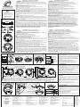
4ESQUEMA DE CONEXIÓN / SCHALTPLAN / DIAGRAMME DE CONNEXION / DIAGRAMMA DI CABLAGGIO
+ (24V)
(Earth)
RL
RL
100K*
*ACHTUNG: Wenn das EOL-Modul nur ein Kondensator ist, IST ES OBLIGATORISCH, am Anfang der Leitung einen Widerstand von 100K parallel hinzuzufügen!
*ATTENTION: Quand le module EOL est juste un capacitor, IL EST OBLIGATOIRE DE CONNECTER UNE RESISTANCE 100K en parallèle au départ de la ligne!
*ATTENZIONE: Quando il EOL-modulo è solo un condensatore, è obbligatorio per collegare una resistenza da 100K in parallelo all'inizio della linea!
*ATENCIÓN: Cuando el módulo EOL es únicamente condensador, ES OBLIGATORIO añadir en paralelo al inicio de la línea una resistencia de 100К!
!
Panel de alarma / Alarmzentrale /
Panneau de detection d'Intrusion /
Centrale Antintrusione
B12L/U
+12V +12V
4. Interrumpa por 2 segundos, como mínimo, la alimentación del detector.
Después de un rearme, el detector pasará a modo de reposo y ambos diodos
LED se apagarán.
El mantenimiento de los detectores deberá efectuarse:
PRUEBA Y MANTENIMIENTO
1. Suministre tensión de alimentación al detector.
2. Espere durante 30 segundos.
3. Influya con un probador térmico (Cordless Heat Detector Tester o Heat Tester
110V>240V) sobre el detector a una distancia de 20 cm. En los límites de 8
segundos después de la influencia, el detector deberá establecerse en estado
de INCENDIO. Ambos diodos luminiscentes se iluminarán simultáneamente.
1. Revisión externa por daños mecánicos visibles: cada semana
2. Inspección de la capacidad de trabajo en condiciones reales: cada mes
3. Limpieza preventiva contra la contaminación de polvo: cada 6 meses
4. Inspección preventiva y limpieza del sistema de contacto: cada 1 año
TEST UND WARTUNG
1. Den Rauchmelder an die Spannungsversorgung legen.
2. 30 Sekunden abwarten.
3. Setzen Sie einen Wärmetester ein (Cordless Heat Detector Tester oder Heat
Tester 110V>240V) in einem Abstand von 20 cm. Innerhalb von 8 Sekunden
muss der Rauchmelder in FEUER-Modus übergehen. Die beiden LED Leuchten
werden gleichzeitig aufleuchten.
4. Die Einspeisung des Rauchmelders für mindestens 2 Sekunden
unterbrechen. Nach diesem Zurücksetzen wird der Rauchmelder in
Dienstmodus übergehen und die beiden LED Leuchten gehen aus.
Die Wartung der Melder umfasst folgende Tätigkeiten:
1. Sichtprüfung zur Feststellung von sichtbaren mechanischen Beschädigungen
– wöchentlich.
2. Betriebstest unter realen Bedingungen – monatlich.
3. Prophylaktische Reinigung von Staubverschmutzungen – alle sechs Monate.
4. Prophylaktische Inspektion und Reinigung des Kontaktsystems – jährlich.
TEST ET MAINTENANCE
1. Alimenter le détecteur.
1. Inspection visuelle pour défauts extérieurs - hebdomadaire.
2. Attendre 30 sec.
3. Approcher le testeur de chaleur (Cordless Heat Detector Tester ou Heat
Tester 110V>240V) à une distance de 20cm pour tester la partie “thermique” du
détecteur. Dans les 8 secondes, le détecteur doit se mettre en mode “FEU”.
Toutes les LEDs s'allument.
4. Débrancher le détecteur pendant au moins 2 secondes. Après le
redémarrage, le détecteur se met en mode veille et les LEDs sont éteintes.
Une bonne maintenance des détecteurs s'effectuent sur le principe
suivant:
2. Test opérationnel en condition réelle – mensuel.
3. Vérification et Nettoyage des poussières et dépôts intérieurs – tous les six
mois.
4. Vérification et nettoyage de la base, des têtes, des connexions - annuelle.
2. Attendere 30 secondi.
3. Applicare simulatore di calore (Cordless Heat Detector Tester o Heat Tester
110V>240V) ad una distanza pari a 20cm per testare la parte "calore". Entro 8
secondi, il rilevatore dovrà entrare in condizione incendio. Si illumineranno
entrambi i LED.
TEST E MANUTENZIONE
2. Test funzionale in condizioni reali - mensile.
4. Spegnere il rivelatore per 1 secondo (minimo). Dopo essersi resettato, il
rivelatore entrerà nella modalità di funzionamento e gli LED si spegneranno.
La manutenzione del rivelatore dovrà includere:
1. Ispezione visiva per danno fisico - settimanale.
1. Alimentare il rivelatore.
3. Pulizia e spolveratura - semestrale.
4. Verifica e pulizia dei contatti e collegamenti della base ed il rivelatore -
annuale.
¡El fabricante se reserva el derecho de realizar
cambios sin notificación previa! /
Ce manuel peut être modifié sans préavis! /
Questo manuale è soggetto a modifiche senza
alcun preavviso!
Der Hersteller behält sich das Recht auf
Änderungen ohne vorherige Ankündigung vor!/
Tensión de alimentación . . . . . . . . . . . . . . . . . . . . . Spannungsversorgung ....................Plage de fonctionnement .............Voltaggio di funzionamento . . . . . . . . . . . . . . 9 - 30 V DC (Nom. 12/24VDC)
Resistencia a humedad relativa. . . . . . . . . . . . . . . . Beständigkeit gegen relative Luftfeuchtigkeit Resistenza all'Umidità Relativa . . . . . . . . . . . (93 ± 3)% @ 40 C...Résistance à l'humidité . . . . . . . . . . . . . . °
Grado de protección . . . . . . . . . . . . . . . . . . . . . . . . Schutzgrade . . . . . . . . . . . . . . . . . . . . . . . . . . . . Degré de protection .................Grado di protezione ....................IP30
Corriente en salida para indicador remoto (RI) ....Strom im Alarmmodus der Klemme RI. . . . . . . . Sortie en mode alarme en RI. . . . . . . . . . Uscita in stato d'allarme a terminale RI . . . . . 20mA (max)/ -3.3V
Peso (con base instalada) ....................Gewicht (mit montiertem Sockel).............Poids (incl. base) ...................Peso (incl. base).......................160g*/170g**
2 2
Sección de cable recomendado . . . . . . . . . . . . . . . Leitungsquerschnitt .......................Section de câble pour terminaux .......Sezione per terminali . . . . . . . . . . . . . . . . . . . 0.4mm ё 2.0mm
Diapasón de la temperatura de funcionamiento ... Temperatura di Funzionamento ...........-10C ё +60CBetriebstemperaturbereich .................Température de fonctionnement . . . . . . . ° °
(Bornes +IN /+OUT). . . . . . . . . . . . . . . . . . . . . . . . . (Klemmen +IN /+OUT).....................(vers les terminaux +IN /+OUT) . . . . . . . (Verso terminali +IN/+OUT)
Dimensiones (con base instalada)..............Abmessungen (mit montiertem Sockel). . . . . . . . Dimensions (incl. base) . . . . . . . . . . . . . . Dimensioni (incl. base). . . . . . . . . . . . . . . . . . ø102mm, h 42mm*/ ø103mm, h 56mm**
- con base tipo B24RD.......................- mit Sockel-Typ B24RD . . . . . . . . . . . . . . . . . . . - avec base type B24RD .............- con base tipo B24RD . . . . . . . . . . . . . . . . . . 33 mA / 12V; 49mA/24V; 57mA/30V
- con base tipo B24, B24-HP y B24D ...........- mit Sockel-Typ B24, B24-HP und B24D ......- avec base type B24, B24-HP et B24D .- con base tipo B24, B24-HP e B24D.......20 mA / 12ё30V
- con base tipo B12L/U ......................- mit Sockel-Typ B12L/U . . . . . . . . . . . . . . . . . . . - avec base type B12L/U . . . . . . . . . . . . . - con base tipo B12L/U. . . . . . . . . . . . . . . . . . 18 mA / 9V; 29mA/12V; 32mA/15V
Clase (en conformidad con EN 54-5) ...........Klasse (EN 54-5) . . . . . . . . . . . . . . . . . . . . . . . . . Classe (en accord avec EN 54-5) . . . . . . Classe (in conformità a EN 54-5) . . . . . . . . . . A1/R
Consumo en estado no activado . . . . . . . . . . . . . . . Verbrauch in nicht aktiviertem Zustand . . . . . . . . Consommation moyenne au repos .....Consumo medio in stato inattivo . . . . . . . . . . < 50µA
Consumo en estado de alarma:. . . . . . . . . . . . . . . . Verbrauch beim Alarm: ....................Tension en état d'alarme:.............Corrente in stato d'allarme:
56
El circuito visto desde arriba
Platte von oben gesehen
Couvercle PCB
PCB visto dall'alto
Pegatina de color (punto)
Farbaufkleber (Punkt)
Echelle de couleur autocollant
Adesivo colorato
CARACTERÍSTCIAS
TÉCNICAS /
DATEN /
SPECIFICHE
TECHNISCHE
TECNICHE
SPECIFICATIONS
TECHNIQUES /
Parámetro de referencia por
la parte externa del cuerpo
Höhenmarke an der Außenseite des Gehäuses
Marquage extérieur sur le corps du détecteur
Tacca di riferimento
Indicación LED / LED Indikation/
Indication LED / LED Indicazioni
Parpadea/ Blinkt /
Clignotement/ Lampeggio
8 sec OK
Iluminada/ Leuchtet /
Lumière on/ Accesi
No iluminada/
Leuchtet nicht/
Lumière off/ Spenti
1!B12L/U (SensoMAG R20 INTR)
Base / Sockel
Jumper
Latch/Unlatch
operation mode
Jumper ON
Latch Mode
Unlatch Mode
Jumper OFF
3
2
B24-HP
B12L/U, B24, B24D, B24RD
B24D B24RD B24/
B24-HP
B24 / B24-HP / B24D / B24RD
* B12L/U, B24, B24D, B24RD ** B24-HP
-
 1
1
-
 2
2


diğer dillerde
- español: Teletek SensoMAG R20 Manual de usuario
- français: Teletek SensoMAG R20 Manuel utilisateur
- italiano: Teletek SensoMAG R20 Manuale utente
- Deutsch: Teletek SensoMAG R20 Benutzerhandbuch
- português: Teletek SensoMAG R20 Manual do usuário
Diğer belgeler
-
SensoMAG F10 B12L-U El kitabı
-
SensoMAG S30 El kitabı
-
Aritech 700 Series Yükleme Rehberi
-
Certa FMR 4030 Quick Manual
-
Bosch Appliances FAS-420-TM Kullanım kılavuzu
-
DeWalt DW074 Kullanım kılavuzu
-
-
-
-
Minelab CTX 3030 Hızlı başlangıç Kılavuzu