
Jig Saw
Stichsäge
™¤Á·
Wyrzynarka
Szúrófűrész
Přímočará pila
Dekupaj
èoÄÁËÍ
Handling instructions
Bedienungsanleitung
√‰ËÁ›Â˜ ¯ÂÈÚÈÛÌÔ‡
Instrukcja obsługi
Kezelési utasítás
Návod k obsluze
Kullanım talimatları
àÌcÚpyÍáËÓ Ôo íÍcÔÎyaÚaáËË
Read through carefully and understand these instructions before use.
Diese Anleitung vor Benutzung des Werkzeugs sorgfältig durchlesen und verstehen.
¢È·‚¿ÛÙ ÚÔÛÂÎÙÈο Î·È Î·Ù·ÓÔ‹ÛÂÙ ·˘Ù¤˜ ÙȘ Ô‰ËÁ›Â˜ ÚÈÓ ÙË ¯Ú‹ÛË.
Przed użytkowaniem należy dokładnie przeczytać niniejszą instrukcję i zrozumieć jej treść.
Használat előtt olvassa el figyelmesen a használati utasítást.
Před použitím si pečlivě přečtěte tento návod a ujistěte se, že mu dobře rozumíte.
Aleti kullanmadan önce bu kılavuzu iyice okuyun ve talimatları anlayın.
BÌËÏaÚeÎëÌo ÔpoäÚËÚe ÀaÌÌyï ËÌcÚpyÍáËï Ôo íÍcÔÎyaÚaáËË ÔpeÊÀe äeÏ ÔoÎëÁoÇaÚëcÓ ËÌcÚpyÏeÌÚoÏ.
FCJ 65V3
•
FCJ 65S3
FCJ65V3
001Cover_FCJ65V3_EE 3/11/09, 15:181

1
8
B
7
2
4
3
1
(b)(a)
5
4 2
1
4
6
5
9
123
0
A
0
C
A
1
4
6
8
3
5
7
2
002Table_FCJ65V3_EE 3/10/09, 19:351

2
G
0
A
8
A
H
E
D
F
10
12
14
9
11
13
002Table_FCJ65V3_EE 3/10/09, 19:352

3
1
2
3
4
5
6
7
8
9
0
A
B
C
D
E
F
G
H
Bıçak tutucu
Alyan anahtarı
Bıçak (bıçaåın keskin
kenarı ön tarafa bakmalı)
Bıçak ayar vidası
Silindir
Tutamaç
Ana ünite
Taban
Talaß/yonga kapaåı
Kılavuz
4mm’lık vida (8mm)
Kıymık muhafazası
Çivi veya ahßap vidası
Ölçek
Kenar oluåu
Gövde kenar çizgisi
Hortum takma ucuna
Kabul edilebilir bıçaklar
ÑepÊaÚeÎë ÔoÎoÚÌa
ÉaeäÌêÈ ÍÎïä Ç ÇËÀe
åecÚËÖpaÌÌoÖo cÚepÊÌÓ
èoÎoÚÌo (ÍpaÈ ÔoÎoÚÌa
ÀoÎÊeÌ ÄêÚë oÄpaçeÌ
ÇÔepeÀ)
ìcÚaÌoÇoäÌêÈ ÇËÌÚ
ÔoÎoÚÌa
PoÎËÍ
ÑepÊaÚeÎë
OcÌoÇÌoÈ ÍopÔyc
OcÌoÇaÌËe
KpêåÍa
cÚpyÊÍocÄopÌËÍa
HaÔpaÇÎÓïçaÓ
4-ÏÏ ÇËÌÚ (8 ÏÏ)
ÂaçËÚÌoe
ÔpËcÔocoÄÎeÌËe
ÉÇoÁÀë ËÎË åypyÔ
òÍaÎa
ÅoÍoÇaÓ ÍaÌaÇÍa
ÉpaÌËáa ÍpoÏÍË ÍopÔyca
KpeÔeÊÌoÈ ÀeÚaÎëï
pyÍaÇa
èpËÏeÌËÏêe ÔoÎoÚÌa
Magyar Čeština Türkçe PyccÍËÈ
Držák listu
Klíč na vnitřní šestihrany
Plátek (Ostří plátku musí
směřovat dopředu)
Stavěcí šroub plátku
Vodicí kladka
Držák
Hlavní jednotka
Základní deska
Kryt proti třískám
Vedení
Šroub 4mm (8mm)
Ochranný kryt proti
odštěpování
Hřebík nebo vrut do dřeva
Stupnice
Boční drážka
Vodící proužek pouzdra
Části k připojení hadice
Povolené řezné plátky
Fűrészlap befogószerkezet
Hatszögletű dugókulcs
Fűrészlap (a fűrészlap
élének előrefelé kell néznie)
Fűrészlap-hernyócsavar
Henger
Tartó
Fő egység
Alapzat
Forgácsvédő fedél
Vezetőelem
4mm-es csavar (8mm)
Forgácsvédő pajzs
Szeg vagy facsavar
Skála
Oldalsó horony
Burkolat szélső vonal
Cső tartozék alkatrészhez.
Elfogadható fűrészlapok
1
2
3
4
5
6
7
8
9
0
A
B
C
D
E
F
G
H
English Deutsch Ελληνικά Polski
Blade holder Sägeblatthalter
Hexagonal bar wrench Sechskantinnenschlüssel
Blade (blade edge must Sägeblatt (Schnittfläche
face front) muß nach vorne zeigen)
Blade set screw
Klemmschraube für das
Sägeblatt
Roller Führungsrolle
Holder Halter
Main unit Hauptgerät
Base Sägetisch
Chip cover Schnipseldeckel
Guide Führungsrolle
4mm screw (8mm) 4mm Schraube (8mm)
Splinter guard Splitterschutz
Nail or wood screw Nagel oder Holzschraube
Scale Skala
Side groove Seitlicher Schlitz
Housing edge line Gehäusekante
Hose attachment part Schlauchanschluss
Acceptable blades
Schlauchanbringungsbereich
Uchwyt ostrza
Klucz sześciokątny
Ostrze (krawędź ostrza
musi być skierowana do
przodu)
Śruba mocująca ostrze
Wałek
Uchwyt
Jednostka główna
Podstawa
Osłona zabezpieczająca
przed odłamkami
Prowadnica
Śruba 4mm (8mm)
Osłona zabezpieczająca
przed odpryskami
Gwóźdź lub wkręt do
drewna
Podziałka
Rowek boczny
Linia krawędzi obudowy
Elementem przyłącza
węża
Odpowiednie ostrza
Στήριγµα λεπίδας
Εάγων κλειδί Άλεν
Λεπίδα (η κψη της
λεπίδας πρέπει να
λέπει µπρστά)
Βίδα λεπίδας
Κύλινδρς
Στήριγµα
Κύρια µνάδα
Βάση
Κάλυµµα ρινισµάτων
"δηγς
Βίδα 4mm (8mm)
Πρ$υλακτήρας σ%ί&ας
Καρ$ί ή ίδα ύλυ
Κλίµακα
Πλευρική εγκπή
"δηγς στερέωσης
Τµήµα στερέωσης τυ
λάστι%υ
Απδεκτές λεπίδες
002Table_FCJ65V3_EE 3/10/09, 19:353

4
Symbols
WARNING
The following show
symbols used for the
machine. Be sure that you
understand their meaning
before use.
Symbole
WARNUNG
Die folgenden Symbole
werden für diese Maschine
verwendet. Achten Sie
darauf, diese vor der
Verwendung zu verstehen.
™‡Ì‚ÔÏ·
¶ƒ√™√Ã∏
Τα παρακάτω δεί%νυν τα
σύµλα πυ %ρησιµπιύνται
στ µη%άνηµα. Βεαιωθείτε τι
κατανείτε τη σηµασίας τυς
πριν τη %ρήση.
Symbole
OSTRZEŻENIE
Następujące oznaczenia to
symbole używane w instrukcji
obsługi maszyny. Upewnij się,
że rozumiesz ich znaczenie
zanim użyjesz narzędzia.
Read all safety warnings
and all instructions.
Failure to follow the
warnings and instructions
may result in electric
shock, fire and/or serious
injury.
Lesen Sie sämtliche
Sicherheitshinweise und
Anweisungen durch.
Wenn die Warnungen und
Anweisungen nicht befolgt
werden, kann es zu
Stromschlag, Brand und/
oder ernsthaften
Verletzungen kommen.
¢È·‚¿˙ÂÙ fiϘ ÙȘ
ÚÔÂȉÔÔÈ‹ÛÂȘ ·ÛÊ·Ï›·˜
Î·È fiϘ ÙȘ Ô‰ËÁ›Â˜.
Η µη τήρηση των
πρειδπιήσεων και
δηγιών µπρεί να
πρκαλέσει
ηλεκτρπληία, πυρκαγιά
και/ή σαρ
τραυµατισµ.
Należy dokładnie zapoznać się
ze wszystkimi ostrzeżeniami i
wskazówkami
bezpieczeństwa.
Nieprzestrzeganie ostrzeżeń
oraz wskazówek
bezpieczeństwa może
spowodować porażenie prądem
elektrycznym, pożar i/lub
odniesienie poważnych obrażeń.
Přečtěte si všechna
varování týkající se
bezpečnosti a všechny
pokyny.
Nedodržení těchto varování
a pokynů může mít za
následek elektrický šok,
požár a/nebo vážné zranění.
Tüm güvenlik uyarılarını
ve tüm talimatları okuyun.
Uyarılara ve talimatlara
uyulmaması elektrik
çarpmasına, yangına ve/
veya ciddi yaralanmaya
neden olabilir.
èpoäÚËÚe Çce ÔpaÇËÎa
ÄeÁoÔacÌocÚË Ë
ËÌcÚpyÍáËË.
He ÇêÔoÎÌeÌËe ÔpaÇËÎ Ë
ËÌcÚpyÍáËÈ ÏoÊeÚ
ÔpËÇecÚË Í ÔopaÊeÌËï
íÎeÍÚpËäecÍËÏ ÚoÍoÏ,
ÔoÊapy Ë/ËÎË cepëeÁÌoÈ
ÚpaÇÏe.
Symboly
UPOZORNĚNÍ
Následující text obsahuje
symboly, které jsou použity
na zařízení. Ujistěte se, že
rozumíte jejich obsahu před
tím, než začnete zařízení
používat.
Simgeler
DÓKKAT
Aßaåıda, bu alet için kullanılan
simgeler gösterilmißtir. Aleti
kullanmadan önce bu
simgelerin ne anlama geldiåini
anladıåınızdan emin olun.
CËÏÇoÎê
èPEÑìèPEÜÑEHàE
HËÊe ÔpËÇeÀeÌê cËÏÇoÎê,
ËcÔoÎëÁyeÏêe ÀÎÓ ÏaåËÌê.
èepeÀ ÌaäaÎoÏ paÄoÚê
oÄÓÁaÚeÎëÌo yÄeÀËÚecë Ç
ÚoÏ, äÚo Bê ÔoÌËÏaeÚe Ëx
ÁÌaäeÌËe.
Only for EU countries
Do not dispose of electric
tools together with
household waste
material!
In observance of
European Directive 2002/
96/EC on waste electrical
and electronic equipment
and its implementation in
accordance with national
law, electric tools that
have reached the end of
their life must be collected
separately and returned to
an environmentally
compatible recycling
facility.
Nur für EU-Länder
Werfen Sie
Elektrowerkzeuge nicht in
den Hausmüll!
Gemäss Europäischer
Richtlinie 2002/96/EG über
Elektro- und Elektronik-
Altgeräte und Umsetzung
in nationales Recht
müssen verbrauchte
Elektrowerkzeuge
getrennt gesammelt und
einer umweltgerechten
Wiederververtung
zugeführt werden.
Mvo για τις %ώρες της
EE
Mηv πετάτε τα ηλεκτρικά
εργαλεία στov κάδo
oικιακώv απoρριµµάτωv!
Σύµ$ωvα µε τηv
εuρωπαϊκή oδηγία 2002/
96/EK περί ηλεκτρικώv και
ηλεκτρovικώv σuσκεuώv
και τηv εvσωµάτωσή της
στo εθvικ δίκαιo, τα
ηλεκτρικά εργαλεία
πρέπει vα σuλλέγovται
ε%ωριστά και vα
επιστρέ$ovται για
αvακύκλωση µε τρπo
$ιλικ πρoς τo
περιάλλov.
Dotyczy tylko państw UE
Nie wyrzucaj elektronarzędzi
wraz z odpadami z
gospodarstwa domowego!
Zgodnie z Europejską
Dyrektywą 2002/96/WE w
sprawie zużytego sprzętu
elektrotechnicznego i
elektronicznego oraz
dostosowaniem jej do prawa
krajowego, zużyte
elektronarzędzia należy
posegregować i zutylizować
w sposób przyjazny dla
środowiska.
Jen pro státy EU
Elektrické nářadí
nevyhazujte do
komunálního odpadu!
Podle evropské směrnice
2002/96/EG o nakládání s
použitými elektrickými a
elektronickými zařízeními a
odpovídajících ustanovení
právních předpisů
jednotlivých zemí se
použitá elektrická nářadí
musí sbírat odděleně od
ostatního odpadu a
podrobit ekologicky
šetrnému recyklování.
Sadece AB ülkeleri için
Elektrikli el aletlerini evdeki
çöp kutusuna atmayınız!
Kullanılmıß elektrikli aletleri,
elektrik ve elektronikli eski
cihazlar hakkındaki 2002/
96/EC Avrupa yönergelerine
göre ve bu yönergeler ulusal
hukuk kurallarına göre
uyarlanarak, ayrı olarak
toplanmalı ve çevre
ßartlarına uygun bir ßekilde
tekrar deåerlendirmeye
gönderilmelidir.
ToÎëÍo ÀÎÓ cÚpaÌ EC
He ÇêÍËÀêÇaÈÚe
íÎeÍÚpoÔpËÄopê ÇÏecÚe c
oÄoêäÌêÏ ÏycopoÏ!
B cooÚÇeÚcÚÇËË c
eÇpoÔeÈcÍoÈ ÀËpeÍÚËÇoÈ
2002/96/EG oÄ yÚËÎËÁaáËË
cÚapêx íÎeÍÚpËäecÍËx Ë
íÎeÍÚpoÌÌêx ÔpËÄopoÇ Ë Ç
cooÚÇeÚcÚÇËË c ÏecÚÌêÏË
ÁaÍoÌaÏË
íÎeÍÚpoÔpËÄopê, ÄêÇçËe
Ç íÍcÔÎyaÚaáËË, ÀoÎÊÌê
yÚËÎËÁoÇêÇaÚëcÓ
oÚÀeÎëÌo ÄeÁoÔacÌêÏ ÀÎÓ
oÍpyÊaïçeÈ cpeÀê
cÔocoÄoÏ.
Jelölések
FIGYELEM
Az alábbiakban a géphez
alkalmazott jelölések
vannak felsorolva. A gép
használata előtt feltétlenül
ismerje meg ezeket a
jelöléseket.
Csak EU-országok számára
Az elektromos
kéziszerszámokat ne dobja
a háztartási szemétbe!
A használt villamos és
elektronikai készülékekről
szóló 2002/96/EK irányelv
és annak a nemzeti jogba
való átültetése szerint az
elhasznált elektromos
kéziszerszámokat külön kell
gyűjteni, és környezetbarát
módon újra kell
hasznosítani.
Olvasson el minden
biztonsági figyelmeztetést
és minden utasítást.
A figyelmeztetések és
utasítások be nem tartása
áramütést, tüzet és/vagy
súlyos sérülést
eredményezhet.
002Table_FCJ65V3_EE 3/10/09, 19:354

5
EnglishEnglish
GENERAL POWER TOOL SAFETY WARNINGS
WARNING
Read all safety warnings and all instructions.
Failure to follow the warnings and instructions may result in
electric shock, fire and/or serious injury.
Save all warnings and instructions for future reference.
The term “power tool” in the warnings refers to your mains-
operated (corded) power tool or battery-operated (cordless)
power tool.
1) Work area safety
a) Keep work area clean and well lit.
Cluttered or dark areas invite accidents.
b) Do not operate power tools in explosive atmospheres,
such as in the presence of flammable liquids, gases
or dust.
Power tools create sparks which may ignite the dust
or fumes.
c) Keep children and bystanders away while operating
a power tool.
Distractions can cause you to lose control.
2) Electrical safety
a) Power tool plugs must match the outlet.
Never modify the plug in any way.
Do not use any adapter plugs with earthed (grounded)
power tools.
Unmodified plugs and matching outlets will reduce
risk of electric shock.
b) Avoid body contact with earthed or grounded surfaces,
such as pipes, radiators, ranges and refrigerators.
There is an increased risk of electric shock if your
body is earthed or grounded.
c) Do not expose power tools to rain or wet conditions.
Water entering a power tool will increase the risk of
electric shock.
d) Do not abuse the cord. Never use the cord for carrying,
pulling or unplugging the power tool.
Keep cord away from heat, oil, sharp edges or moving
parts.
Damaged or entangled cords increase the risk of
electric shock.
e) When operating a power tool outdoors, use an
extension cord suitable for outdoor use.
Use of a cord suitable for outdoor use reduces the
risk of electric shock.
f) If operating a power tool in a damp location is
unavoidable, use a residual current device (RCD)
protected supply.
Use of an RCD reduces the risk of electric shock.
3) Personal safety
a) Stay alert, watch what you are doing and use common
sense when operating a power tool.
Do not use a power tool while you are tired or under
the influence of drugs, alcohol or medication.
A moment of inattention while operating power tools
may result in serious personal injury.
b) Use personal protective equipment. Always wear eye
protection.
Protective equipment such as dust mask, non-skid
safety shoes, hard hat, or hearing protection used for
appropriate conditions will reduce personal injuries.
c) Prevent unintentional starting. Ensure the switch is
in the off-position before connecting to power source
and/or battery pack, picking up or carrying the tool.
Carrying power tools with your finger on the switch
or energising power tools that have the switch on
invites accidents.
d) Remove any adjusting key or wrench before turning
the power tool on.
A wrench or a key left attached to a rotating part of
the power tool may result in personal injury.
e) Do not overreach. Keep proper footing and balance
at all times.
This enables better control of the power tool in
unexpected situations.
f) Dress properly. Do not wear loose clothing or
jewellery. Keep your hair, clothing and gloves away
from moving parts.
Loose clothes, jewellery or long hair can be caught
in moving parts.
g) If devices are provided for the connection of dust
extraction and collection facilities, ensure these are
connected and properly used.
Use of dust collection can reduce dust related hazards.
4) Power tool use and care
a) Do not force the power tool. Use the correct power
tool for your application.
The correct power tool will do the job better and safer
at the rate for which it was designed.
b) Do not use the power tool if the switch does not
turn it on and off.
Any power tool that cannot be controlled with the
switch is dangerous and must be repaired.
c) Disconnect the plug from the power source and/or
the battery pack from the power tool before making
any adjustments, changing accessories, or storing
power tools.
Such preventive safety measures reduce the risk of
starting the power tool accidentally.
d) Store idle power tools out of the reach of children
and do not allow persons unfamiliar with the power
tool or these instructions to operate the power tool.
Power tools are dangerous in the hands of untrained
users.
e) Maintain power tools. Check for misalignment or
binding of moving parts, breakage of parts and any
other condition that may affect the power tool's
operation.
If damaged, have the power tool repaired before use.
Many accidents are caused by poorly maintained
power tools.
f) Keep cutting tools sharp and clean.
Properly maintained cutting tools with sharp cutting
edges are less likely to bind and are easier to control.
g) Use the power tool, accessories and tool bits etc. in
accordance with these instructions, taking into
account the working conditions and the work to be
performed.
Use of the power tool for operations different from
those intended could result in a hazardous situation.
5) Service
a) Have your power tool serviced by a qualified repair
person using only identical replacement parts.
This will ensure that the safety of the power tool is
maintained.
PRECAUTION
Keep children and infirm persons away.
When not in use, tools should be stored out of reach of children and
infirm persons.
01Eng_FCJ65V3_EE 3/10/09, 19:355

6
English
SPECIFICATIONS
Model FCJ65V3 FCJ65S3
Voltage (by areas)* (110V, 115V, 120V, 127V, 220V, 230V, 240V)
Power input 400W*
Wood: 65mm
Max. cutting depth
Mild steel: 6mm
No-load speed 0 – 3000 min
–1
3000
min
–1
Stroke 18mm
Min. cutting radius 25mm
Weight (without cord) 1.5kg
* Be sure to check the nameplate on product as it is subject to change by areas.
STANDARD ACCESSORIES
(1) Blade No.31 ................................................................. 1
For cutting thick lumber
(2) Splinter guard ............................................................. 1
(3) Chip cover ................................................................... 1
(4) Hexagonal bar wrench ............................................... 1
Standard accessories are subject to change without
notice.
OPTIONAL ACCESSORIES (sold separately)
(1) Blades, No.1 – No.6, 31*
* No.31 Blade is a standard accessory.
(2) Guide
Optional accessories are subject to change without notice.
APPLICATIONS
䡬 Cutting various lumber and pocket cutting
䡬 Cutting mild steel plate, aluminum plate, and copper
plate
䡬 Cutting synthetic resins, such as phenol resin and
vinyl chloride
䡬 Cutting thin and soft construction materials
PRIOR TO OPERATION
1. Power source
Ensure that the power source to be utilized conforms
to the power requirements specified on the product
nameplate.
2. Power switch
Ensure that the power switch is in the OFF position. If
the plug is connected to a receptacle while the power
switch is in the ON position, the power tool will start
operating immediately, which could cause a serious
accident.
3. Extension cord
When the work area is removed from the power
source, use an extension cord of sufficient thickness
and rated capacity. The extension cord should be
kept as short as practicable.
MOUNTING THE BLADE
1. Use the accessory hexagonal bar wrench to loosen
the blade set screws on the blade holder, as shown in
Fig. 1(a).
2. Holding the blade with its cutting edge facing the
front, insert the mounting portion of the blade into
the plunger groove until it touches the bottom of the
groove.
3. As shown in Fig. 1(b), firmly clamp the side screw.
CAUTION
䡬 Loosened set screws may cause the blade to be
damaged. Always ensure that the set screws are
securely tightened. Always ensure that the plunger
groove is clean and clear of sawdust to ensure proper
blade mounting and set screw clamping.
4. Storing the hexagonal bar wrench
(1) Insert in a hole on the side of the main unit with
holding the short side horizontally as shown in
Fig. 2.
(2) Rotate with the hexagonal bar wrench inserted and
secure as shown in Fig. 2.
ADJUSTING THE GUIDE ROLLER
The guide roller, shown in Fig. 3, is employed to prevent
the blade from snapping. Prior to use, adjust guide roller
in accordance with the following procedures:
(1) Loosen the holder set screw with the accessory
hexagonal bar wrench.
(2) Gently slide the guide roller until the roller groove
lightly touches the back of the blade.
NOTE
On delivery from the factory, there is a gap of about
3mm between the roller and blade.
(3) Firmly tighten the holder set screw.
CAUTION
䡬 The guide roller can be used only for Blades that
have a straight line on the rear that is longer than
50mm. (Fig. 4A and 4B) When using other types
of blades (Fig. 4C), slide the guide roller in
backwards so that the guide roller does not contact
the blade.
䡬 When cutting thick boards or performing
continuous cutting operations, use the blade
shown in the Fig. 4A, 4B and be sure to set the
guide roller.
CHIP COVER POSITIONING
1. Chip cover
Use the chip cover to reduce flying of cut particles
and to easily operate the saw.
01Eng_FCJ65V3_EE 3/10/09, 19:356

7
EnglishEnglish
Slide the chip cover while lightly pressing its front
section.
The chip cover can be set at three positions as shown
in Fig. 5.
2. How to choose the position of the ship cover
Set the chip cover to the first step when attaching or
removing the blade.
Set the chip cover to the second step when cutting
wooden materials.
Set the chip cover to the second or third step when
cutting metal materials such as steel.
CAUTION
䡬 Keep always the chip cover in the low position when
operating the tool.
䡬 Wear protection glasses even if the chip cover is
used.
ADJUSTING THE BLADE OPERATING
SPEED ........................................... (FCJ65V3 only)
NOTE
The blade operating speed cannot be adjusted for
FCJ65S3.
The blade operating speed can be adjusted within a
range of 0 to 3,000 min
–1
according to the degree that the
trigger switch is depressed. Select the speed appropriate
to the material being worked and/or the working
conditions.
To achieve continuous operation, pull the trigger switch
all the way back and depress the stopper. Then, turn the
speed adjustment knob to adjust the blade operating
speed as desired.
NOTE
The speed adjustment knob rotates approximately 1.5
turns. To turn the switch OFF, pull the trigger switch
again to disengage the stopper, and release the trigger
switch.
CUTTING
CAUTION
䡬 While sawing, the base must be firmly in contact with
the material surface, and the blade must be held at a
right angle. If the base becomes separated from the
material, it could cause the blade to break.
䡬 When cutting while holding the front surface, be
careful of the moving blade and hold the upper part
firmly.
1. Rectilinear cutting
(1) To ensure accurate rectilinear cutting, employ the
optional accessory guide as shown in Fig. 6.
(2) Use the splinter guard to reduce roughness of the
cutting surface of wooden materials. Attach the
splinter guard by inserting it from the front section of
the base until it clicks into place. (Fig. 7)
CAUTION
Set the base in the front position when using the
splinter guard.
2. Cutting a circle or a circular arc
To ensure efficient cutting, employ the optional
accessory guide and nail or wood screw as shown in
Fig. 8.
When mounting the guide, loosen the base bottom
screw, and shift the base as far forward as it will go.
3. Sawing curved lines
When sawing a small circular arc, reduce the feeding
speed of the machine. If the machine is fed too fast, it
could cause the blade to break.
4. Cutting metallic materials
Always use an appropriate cutting agent (spindle oil,
soapy water, etc.). When a liquid cutting agent is not
available, apply grease to the back surface of the
material to be cut.
5. Pocket cutting
(1) In lumber
Aligning the blade direction with the grain of the
wood, cut step by step until a window hole is cut in
the center of the lumber. (Fig. 9)
(2) In other materials
When cutting a window hole in materials other than
lumber, initially bore a hole with a drill or similar tool
from which to start cutting.
6. Angular cutting
Set the chip cover to the first step. (Fig. 5)
To adjust the angle of inclination; loosen the base
bottom screw, shift the base position to the side
groove of the semicircular portion, align the scale on
the base semicircular portion (figures engraved on
the scale indicate the angle of inclination) with the
housing edge line, and thoroughly tighten the base
bottom screw. (Fig. 10 and 11)
CAUTION
Set the screw to the opposite side of the inclining
side when using the guide. (Fig. 12)
7. Dust produced in operation
CAUTION
䡬 To prevent accidents, turn the switch off and remove
the plug from the power supply when not in use.
䡬 For instruction on using the dust collector and
applicable cutting debris, please read the dust
collector instruction manual.
The dust produced in normal operation may affect
the operator’s health. Either of following way is
recommended.
a) Wear a dust mask
b) Use external dust collection equipment
When using the external dust collection equipment,
connect the rubber adapter (accessory of external
dust collection equipment) with end the of hose from
external dust collection equipment.
Then connect the another end of rubber adapter with
the hose attachment part that positioned in rear end
of jig saw. (See Fig. 13)
SELECTION OF BLADES
1. Accessory blades
To ensure maximum operating efficiency and results
it is very important to select the appropriate blade
best suited to the type and thickness of the material
to be cut. One type of blade is provided as standard
accessory. The blade number is engraved in the
vicinity of the mounting portion of each blade. Select
appropriate blades by referring to Table 1.
01Eng_FCJ65V3_EE 3/10/09, 19:357

8
English
Table 1 List of Appropriate Blades
Material to be cut Material quality Blade No.
Lumber
General lumber
No.1 or No.31 (thick plate) or No.41 (thick
plate) or No.2 (thin plate)
Plywood No.3 or No.6
Iron plate Mild steel plate No.6
Nonferrous metal Aluminum, copper, brass No.6
Phenol resin, melamine resin, etc. No.4 (thick plate) or No.6 (thin plate)
Synthetic resin
Vinyl chloride, acryl resin, etc.
No.2 or No.4 (thick plate) or No.6
(thin plate)
Foamed styrol, etc. No.2
Pulp
Cardboard, corrugated paper No.2
Hardboard No.5 or No.6
Fiberboard No.6
Others
Hard rubber No.2
Slate No.5
2. Acceptable commercial blades (Fig. 14)
This machine is designed to accept most blades
available on the open market. As illustrated in
Fig. 14, blade dimension restrictions are as follows:
䡬 Thickness : L2 ..... Less than 1.6mm
䡬 Width : L3 ..... 6.3mm
L4 ..... 8mm
L5 ..... 7mm
NOTE
When cutting thick materials, use HITACHI genuine blades
which have an inclination as shown in Fig. 4-A or B.
MAINTENANCE AND INSPECTION
1. Inspecting the blade
Continued use of a dull or damaged blade will result
in reduced cutting efficiency and may cause
overloading of the motor. Replace the blade with a
new one as soon as excessive abrasion is noted.
2. Inspecting the mounting screws
Regularly inspect all mounting screws and ensure
that they are properly tightened. Should any of the
screws be loose, retighten them immediately. Failure
to do so could result in serious hazard.
3. Maintenance of the motor
The motor unit winding is the very “heart” of the
power tool. Exercise due care to ensure the winding
does not become damaged and/or wet with oil or
water.
4. Replacing supply cord
If the supply cord of Tool is damaged, the Tool must
be returned to Hitachi Authorized Service Center for
the cord to be replaced.
5. Servicing
Consult an authorized Service Agent in the event of
power tool failure.
6. Service parts list
A: Item No.
B: Code No.
C: No. Used
D: Remarks
CAUTION
Repair, modification and inspection of Hitachi Power
Tools must be carried out by a Hitachi Authorized
Service Center.
This Parts List will be helpful if presented with the
tool to the Hitachi Authorized Service Center when
requesting repair or other maintenance.
In the operation and maintenance of power tools, the
safety regulations and standards prescribed in each
country must be observed.
MODIFICATION
Hitachi Power Tools are constantly being improved
and modified to incorporate the latest technological
advancements.
Accordingly, some parts (i.e. code numbers and/or
design) may be changed without prior notice.
GUARANTEE
We guarantee Hitachi Power Tools in accordance with
statutory/country specific regulation. This guarantee does
not cover defects or damage due to misuse, abuse, or
normal wear and tear. In case of complaint, please send
the Power Tool, undismantled, with the GUARANTEE
CERTIFICATE found at the end of this Handling
instruction, to a Hitachi Authorized Service Center.
NOTE
Due to HITACHI’s continuing program of research and
development, the specifications herein are subject to
change without prior notice.
Information concerning airborne noise and vibration
The measured values were determined according to
EN60745 and declared in accordance with ISO 4871.
[FCJ65V3]
Measured A-weighted sound power level: 95 dB (A).
Measured A-weighted sound pressure level: 84 dB (A).
Uncertainty KpA: 3 dB (A).
Wear ear protection.
The typical weighted root mean square acceleration
value: 10.2 m/s
2
.
01Eng_FCJ65V3_EE 3/10/09, 19:358

9
Deutsch
ALLGEMEINE SICHERHEITSHINWEISE FÜR
ELEKTROGERÄTE
WARNUNG
Lesen Sie sämtliche Sicherheitshinweise und Anweisungen durch.
Wenn die Warnungen und Anweisungen nicht befolgt werden,
kann es zu Stromschlag, Brand und/oder ernsthaften Verletzungen
kommen.
Bitte bewahren Sie alle Warnhinweise und Anweisungen zum
späteren Nachschlagen auf.
Der Begriff „Elektrowerkzeug“ bezieht sich in den Warnhinweisen
auf Elektrowerkzeuge mit Netz- (schnurgebunden) oder Akkubetrieb
(schnurlos).
1) Sicherheit im Arbeitsbereich
a) Sorgen Sie für einen sauberen und gut ausgeleuchteten
Arbeitsbereich.
Zugestellte oder dunkle Bereiche ziehen Unfälle förmlich
an.
b) Verwenden Sie Elektrowerkzeuge niemals an Orten, an
denen Explosionsgefahr besteht – zum Beispiel in der
Nähe von leicht entflammbaren Flüssigkeiten, Gasen
oder Stäuben.
Bei der Arbeit mit Elektrowerkzeugen kann es zu
Funkenbildung kommen, wodurch sich Stäube oder
Dämpfe entzünden können.
c) Sorgen Sie bei der Arbeit mit Elektrowerkzeugen dafür,
dass sich keine Zuschauer (insbesondere Kinder) in der
Nähe befinden.
Wenn Sie abgelenkt werden, können Sie die Kontrolle
über das Werkzeug verlieren.
2) Elektrische Sicherheit
a) Elektrowerkzeuge müssen mit passender
Stromversorgung betrieben werden.
Nehmen Sie niemals irgendwelche Änderungen am
Anschlussstecker vor.
Verwenden Sie bei Elektrowerkzeugen mit Schutzkontakt
(geerdet) niemals Adapterstecker.
Stecker im Originalzustand und passende Steckdosen
reduzieren das Stromschlagrisiko.
b) Vermeiden Sie Körperkontakt mit geerdeten
Gegenständen wie Rohrleitungen, Heizungen, Herden
oder Kühlschränken.
Bei Körperkontakt mit geerdeten Gegenständen besteht
ein erhöhtes Stromschlagrisiko.
c) Setzen Sie Elektrowerkzeuge niemals Regen oder
sonstiger Feuchtigkeit aus.
Wenn Flüssigkeiten in ein Elektrowerkzeug eindringen,
erhöht sich das Stromschlagrisiko.
d) Verwenden Sie die Anschlussschnur nicht missbräuchlich.
Tragen Sie das Elektrowerkzeug niemals an der
Anschlussschnur, ziehen Sie es nicht damit heran und
ziehen Sie den Stecker nicht an der Anschlussschnur aus
der Steckdose.
Halten Sie die Anschlussschnur von Hitzequellen, Öl,
scharfen Kanten und beweglichen Teilen fern.
Beschädigte oder verdrehte Anschlussschnüre erhöhen
das Stromschlagrisiko.
e) Wenn Sie ein Elektrowerkzeug im Freien benutzen,
verwenden Sie ein für den Außeneinsatz geeignetes
Verlängerungskabel.
Ein für den Außeneinsatz geeignetes Kabel vermindert
das Stromschlagrisiko.
f) Falls sich der Betrieb des Elektrowerkzeuges in feuchter
Umgebung nicht vermeiden lässt, verwenden Sie eine
Stromversorgung mit Fehlerstromschutzeinrichtung
(Residual Current Device, RCD).
Durch den Einsatz einer Fehlerstromschutzeinrichtung
wird das Risiko eines elektrischen Schlages reduziert.
3) Persönliche Sicherheit
a) Bleiben Sie wachsam, achten Sie auf das, was Sie tun,
und setzen Sie Ihren Verstand ein, wenn Sie mit
Elektrowerkzeugen arbeiten.
Benutzen Sie keine Elektrowerkzeuge, wenn Sie müde
sind oder unter Einfluss von Drogen, Alkohol oder
Medikamenten stehen.
Bei der Arbeit mit Elektrowerkzeugen können bereits
kurze Phasen der Unaufmerksamkeit zu schweren
Verletzungen führen.
b) Benutzen Sie eine persönliche Schutzausrüstung. Tragen
Sie immer einen Augenschutz.
Schutzausrüstung wie Staubmaske, rutschsichere
Sicherheitsschuhe, Schutzhelm und Gehörschutz senken
das Verletzungsrisiko bei angemessenem Einsatz.
c) Vermeiden Sie unbeabsichtigten Anlauf. Achten Sie
darauf, dass sich der Schalter in der Aus- (Off-) Position
befindet, ehe Sie das Gerät mit der Stromversorgung
und/oder Batteriestromversorgung verbinden, es
aufheben oder herumtragen.
Das Herumtragen von Elektrowerkzeugen mit dem Finger
am Schalter oder das Herstellen der Stromversorgung bei
betätigtem Schalter zieht Unfälle regelrecht an.
d) Entfernen Sie sämtliche Einstellwerkzeuge
(Einstellschlüssel), ehe Sie das Elektrowerkzeug
einschalten.
Ein an einem beweglichen Teil des Elektrowerkzeugs
angebrachter Schlüssel kann zu Verletzungen führen.
e) Sorgen Sie für einen festen Stand. Achten Sie jederzeit
darauf, sicher zu stehen und das Gleichgewicht zu
bewahren.
Dadurch haben Sie das Elektrowerkzeug in unerwarteten
Situationen besser im Griff.
f) Kleiden Sie sich richtig. Tragen Sie keine lose Kleidung
oder Schmuck. Halten Sie Haar, Kleidung und Handschuhe
von beweglichen Teilen fern.
Lose Kleidung, Schmuck oder langes Haar kann von
beweglichen Teilen erfasst werden.
g) Wenn Anschlüsse für Staubabsaug- und -
sammelvorrichtungen vorhanden sind, sorgen Sie dafür,
dass diese richtig angeschlossen und eingesetzt werden.
Durch Entfernen des Staubes können staubbezogene
Gefahren vermindert werden.
4) Einsatz und Pflege von Elektrowerkzeugen
a) Überanspruchen Sie Elektrowerkzeuge nicht. Benutzen
Sie das richtige Elektrowerkzeug für Ihren Einsatzzweck.
Das richtige Elektrowerkzeug erledigt seine Arbeit bei
bestimmungsgemäßem Einsatz besser und sicherer.
b) Benutzen Sie das Elektrowerkzeug nicht, wenn es sich
nicht am Schalter ein- und ausschalten lässt.
Jedes Elektrowerkzeug, das nicht mit dem Schalter betätigt
werden kann, stellt eine Gefahr dar und muss repariert
werden.
c) Stecken Sie den Stecker der Stromversorgung oder
Batteriestromversorgung vom Gerät ab, ehe Sie
Einstellarbeiten vornehmen, Zubehörteile tauschen oder
das Elektrowerkzeug verstauen.
Solche präventiven Sicherheitsmaßnahmen verhindern
den unbeabsichtigten Anlauf des Elektrowerkzeugs und
die damit verbundenen Gefahren.
d) Lagern Sie nicht benutzte Elektrowerkzeuge außerhalb
der Reichweite von Kindern, lassen Sie nicht zu, dass
Personen das Elektrowerkzeug bedienen, die nicht mit
dem Werkzeug selbst und/oder diesen Anweisungen
vertraut sind.
Elektrowerkzeuge in ungeschulten Händen sind gefährlich.
e) Halten Sie Elektrowerkzeuge in Stand. Prüfen Sie auf
Fehlausrichtungen, sicheren Halt und Leichtgängigkeit
beweglicher Teile, Beschädigungen von Teilen und auf
jegliche andere Zustände, die sich auf den Betrieb des
Elektrowerkzeugs auswirken können.
02Ger_FCJ65V3_EE 3/10/09, 19:359

10
Deutsch
TECHNISCHE DATEN
Modell FCJ65V3 FCJ65S3
Spannung (je nach Gebiet)* (110V, 115V, 120V, 127V, 220V, 230V, 240V)
Leistungsaufnahme 400W*
Holz: 65mm
Max. Schnittiefe
Flußstahl: 6mm
Leerlaufhubzahlen 0
–
3000 min
–1
3000 min
–1
Hub 18mm
Mindestschnittradius 25mm
Gewicht (ohne kabel) 1,5kg
* Vergessen Sie nicht, die Produktangaben auf dem Typenschild zu überprüfen, da sich diese je nach Verkaufsgebiet
ändern.
STANDARDZUBEHÖR
(1) Sägeblatt Nr.31 ........................................................... 1
Für Schneiden von dickem Bauholz
(2) Splitterschutz .............................................................. 1
(3) Schnipseldeckel .......................................................... 1
(4) Innensechskantschlüssel ........................................... 1
Das Standardzubehör kann ohne vorherige
Bekanntmachung jederzeit geändert werden.
SONDERZUBEHÖR (separat zu beziehen)
(1) Sägeblätter, Nr.1 – Nr.6, Nr.31*
* Sägeblatt Nr.31 ist Standardzubehör.
(2) Führungsrolle
Das Sonderzubehör kann ohne vorherige
Bekanntmachung jederzeit geändert werden.
ANWENDUNGEN
䡬 Schneiden verschiedener Nutzhölzer (auch
Aussparungen)
䡬 Schneiden von Flußstahlblechen, Aluminiumblechen
und Kupferblechen
䡬 Schneiden von Kunstharzen wie Phenolharz und
Vinylchlorid
䡬 Schneiden von dünnen und weichen Baumaterialien
VOR DER INBETRIEBNAHME
1. Netzspannung
Prüfen, daß die zu verwendende Netzspannung der
Angabe auf dem Typenschild entspricht.
Bei Beschädigungen lassen Sie das Elektrowerkzeug
reparieren, ehe Sie es benutzen.
Viele Unfälle mit Elektrowerkzeugen sind auf schlechte
Wartung zurückzuführen.
f) Halten Sie Schneidwerkzeuge scharf und sauber.
Richtig gewartete Schneidwerkzeuge mit scharfen
Schneidkanten bleiben weniger häufig hängen und sind
einfacher zu beherrschen.
g) Benutzen Sie Elektrowerkzeuge, Zubehör,
Werkzeugspitzen und Ähnliches in Übereinstimmung mit
diesen Anweisungen – beachten Sie dabei die jeweiligen
Arbeitsbedingungen und die Art und Weise der
auszuführenden Arbeiten.
2. Netzschalter
Prüfen, daß der Netzschalter auf “AUS” steht. Wenn
der Stecker an das Netz angeschlossen wird, während
der Schalter auf “EIN” steht, beginnt das Werkzeug
sofort zu laufen, was gefährlich ist.
3. Verlängerungskabel
Wenn der Arbeitsbereich nicht in der Nähe des
Netzanschlusses liegt, ist ein Verlängerungskabel
ausreichenden Querschnitts und ausreichender
Nennleistung zu verwenden. Das Verlängerungskabel
sollte so kurz wie möglich gehalten werden.
ANBRINGEN DES SÄGEBLATTS
1. Lösen Sie die Klemmschrauben am Sägeblatthalter
mit dem Sechskantschlüssel, wie in Abb. 1(a) gezeigt.
2. Das Sägeblatt mit der Schnittseite nach vorn halten
und den Befestigungsteil des Sägeblatts bis zum
Anschlag in den Schlitz der Schwingspule
einschieben.
3. Gemäß Abb. 1(b) wird die seitliche Klemmschraube
fest angezogen.
ACHTUNG
䡬 Lose Klemmschrauben können zur Beschädigung des
Sägeblattes führen. Es ist immer darauf zu achten,
daß die Klemmschrauben fest angezogen sind. Es ist
ferner darauf zu achten, daß der Schlitz der
Schwingspule sauber und ohne Sägemehl ist, um
eine richtige Befestigung des Sägeblattes und
richtiges Klemmen der Klemmschrauben zu
gewährleisten.
Der Gebrauch des Elektrowerkzeuges für andere als die
vorgesehenen Anwendungen kann zu gefährlichen
Situationen führen.
5) Service
a) Lassen Sie Elektrowerkzeuge durch qualifizierte
Fachkräfte und unter Einsatz passender, zugelassener
Originalteile warten.
Dies sorgt dafür, dass die Sicherheit des Elektrowerkzeugs
nicht beeinträchtigt wird.
VORSICHT
Von Kindern und gebrechlichen Personen fernhalten.
Werkzeuge sollten bei Nichtgebrauch außerhalb der Reichweite
von Kindern und gebrechlichen Personen aufbewahrt werden.
02Ger_FCJ65V3_EE 3/10/09, 19:3510

11
Deutsch
4. Verstauen des Sechskantschlüssels
(1) Schieben Sie den Schlüssel in die seitliche
Gehäuseöffnung ein, halten Sie das kurze Ende dabei
waagerecht (siehe Abb. 2).
(2) Fixieren Sie den Sechskantschlüssel, wie in Abb. 2
gezeigt, durch Drehen.
EINSTELLEN DER FÜHRUNGSROLLE
Die Führungsrolle wird, wie in Abb. 3 gezeigt, verwendet,
um das Abspringen des Sägeblattes zu verhindern. Vor
der Benutzung wird die Führungsrolle wie folgt
eingestellt:
(1) Die Klemmschraube des Halters wird mit dem
Sechskantinnenschlüssel gelockert.
(2) Die Führungsrolle vorsichtig verschieben, bis die
Rollennut leicht die Rückseite des Sägeblatts berührt.
ANMERKUNG
Bei Lieferung ab Werk ist ein Zwischenraum von
etwa 3mm zwischen der Rolle und dem Sägeblatt
vorhanden.
(3) Die Klemmschraube des Halters wird fest angezogen.
ACHTUNG
䡬 Die Führungswalze kann nur für Sägeblätter
verwendet werden, die hinten eine gerade Linie
von mehr als 50mm Länge haben. (Abb. 4A und
4B) Bei Verwendung anderer Sägeblätter (Abb.
4C) die Führungswalze in Rückwärtsrichtung
einschieben, so daß die Führungswalze nicht das
Sägeblatt berührt.
䡬 Beim Schneiden dicker Bretter und bei
fortgesetzten Schneidevorgängen das in Abb. 4A,
4B gezeigte Blatt verwenden und unbedingt die
Führungsrolle einstellen.
LAGE DES SCHNIPSELDECKELS
1. Schnipseldeckel
Den Schnipseldeckel verwenden, um das Spritzen
von Schnittpartikeln zu vermeiden und die Säge leicht
zu bedienen.
Zum Aufsetzen des Schnipseldeckels leicht die
Vorderseite drücken.
Der Schnipseldeckel kann in drei Stellungen
aufgesetzt werden, wie in Abb. 5 gezeigt.
2. Wahl der Position des Schipseldeckels
Den Schipseldeckel beim Anbringen oder Abnehmen
des Sägeblattes in die erste Stellung stellen.
Den Schipseldeckel beim Sägen von Holzmaterialien
in die zweite Stellung stellen.
Den Schnipseldeckel beim Sägen von
Metallmaterialien wie Blech in die dritte stellung
stellen.
ACHTUNG
䡬 Halten Sie die Späneabdeckung beim Betrieb des
Werkzeugs immer in der niedrigen Position.
䡬 Immer eine Schutzbrille tragen, auch wenn der
Schnipseldeckel verwendet wird.
EINSTELLEN DER ARBEITSGESCHWINDIGKEIT
DES SÄGEBLATTES ..................... (Nur FCJ65V3)
ANMERKUNG
Die Sägeblattgeschwindigkeit kann beim Modell
FCJ65S3 nicht eingestellt werden.
Die Arbeitsgeschwindigkeit des Sägeblattes kann
innerhalb eines Bereichs von 0 bis 3000 min
–1
je nach
Druck auf den Drückerschalter eingestellt werden. Die
für das Material des Arbeisstückes und/oder die
Arbeitsbedingungen geeignete Geschwindigkeit wird
gewählt. Für kontinuierlichen Betrieb wird der
Drückerschalter ganz zurückgezogen und der
Arretierknopf gedrückt. Dann wird der Knopt für die
Geschwindigkeitsregelung zur Einstellung der
gewünschten Arbeitsgeschwindigkeit des Sägeblattes
eingestellt.
ANMERKUNG
Der Einstellknopf für die Geschwindigkeit hat etwa 1,5
Umdrehungen. Zum Ausschalten wird der
Drückerschalter erneut gezogen, so daß der Arretierknopf
freigegeben wird, und dann wird der Drückerschalter
losgelassen.
SCHNEIDEN
ACHTUNG
䡬 Beim Sägen muß der Sägetisch fest auf der
Oberfläche des Werkstücks auf liegen und das
Sägeblatt im rechten Winkel gehalten werden. Wenn
der Sägetisch das Material nicht berührt, kann das
zum zerbrechen des Sägeblatts führn.
䡬 Wenn Sie beim Schneiden die Vorderseite halten,
auf das sich auf-und abbewegende Sägeblatt achten
und das Oberteil festhalten.
1. Parallelschneiden
(1) Für genaues, geradliniges Schneiden den
Sonderzubehörführer wie auf Abb. 6 gezeigt
verwenden.
(2) Den Splitterschuz verwenden, um die Rauhigkeit der
Sägefläche von Holzmaterialien zu verringern. Der
Splitterschutz wird von der Vordersektion des
Sägetischs eingesetzt, bis er einrastet. (Abb. 7)
ACHTUNG
Den Sägetisch nach vorne stellen, wenn der
Splitterschutz verwendet wird.
2. Schneiden eines Kreises oder eines Kreisbogens
Um zweckmäßiges Schneiden zu erreichen,
Sonderzubehörführer, Nagel und Holzschraube wie
auf Abb. 8 gezeigt verwenden.
Zum Anbringen des Führers die Bodenschraube
lockern und den Boden soweit wie möglich nach
vorn schieben.
3. Sägen von Bogenlinienj
Beim Sägen eines kleinen Kreisbogens wird die
Schiebgeschwindigkeit der Maschine verringert.
Wenn die Maschine zu schnell geschoben wird, könnte
das zum zerbrechen des Sägeblatts führen.
4. Schneiden von Metallen
Immer ein geeignetes Schneidemittel verwenden
(Spindelöl, Seifenwasser, usw.). Wenn ein flüssiges
Schneidemittel nicht zur Verfügung steht, wird auf
die Rückseite des zu schneidenden Materials Fett
aufgetragen.
5. Schneiden von Löchern
(1) In Schnittholz
Die Schnittrichtung wird der Faserrichtung des Holzes
angepasst. Es wird Schritt für Schritt geschnitten, bis
ein Fenster in der Mitte des Schnittholzes entstanden
ist. (Abb. 9)
02Ger_FCJ65V3_EE 3/10/09, 19:3511

12
Deutsch
(2) In anderen Materialien
Beim Schneiden eines Fensters in anderen Materialien
als Holz wird zu Anfang ein Loch mit einer
Bohrmaschine oder einem ähnlichen Werkzeug
gebohrt, von dem aus das Schneiden beginnt.
6. Schrägschnitte
Den Schnipseldeckel in die erste Stellung stellen.
(Abb. 5)
Für die Einstellung des Neigungswinkels wird die
Bodenschraube gelockert, die Position des Bodens
am seitlichen Schlitz der Halbkreisführung verschoben
und die Skala auf der Halbkreisführung (die auf der
Skala eingravierten Zahlen bedeuten den
Neigungswinkel) mit der Gehäusekante eingereiht,
und die bodenschraube fest angezogen. (Abb. 10
und 11)
ACHTUNG
Bei Verwendung der Führungsrolle die Schraube in
die der Neigeseite entgegengesetzten Seite stellen.
(Abb. 12)
7. Im Betrieb anfallender Staub
ACHTUNG
䡬 Damit es nicht zu Unfällen kommt, schalten Sie den
Strom ab und ziehen den Netzstecker, wenn Sie das
Gerät nicht verwenden.
䡬 Eine Anleitung zur Verwendung des Staubsammlers
zum Absaugen von Sägespänen und Staub finden
Sie in der Bedienungsanleitung zum Staubsammler.
Im Betrieb anfallender Staub kann
gesundheitsschädlich sein. Wir empfehlen Folgendes.
a) Tragen Sie eine Staubschutzmaske
b) Nutzen Sie eine externe Staubabsaugvorrichtung
Wenn Sie den externen Staubsammler verwenden,
stecken Sie das Gummi-Adapterstück
(Staubsammlerzubehör) auf das Schlauchende des
externen Staubsammlers.
Stecken Sie anschließend das andere Ende des
Gummi-Adapterstücks auf den Schlauchanschluss
am hinteren Ende der Stichsäge. (siehe Abb. 13)
AUSWAHL DER SÄGEBLÄTTER
1. Standardmaßiges Zubehör
Für maximale Leistung und beste Ergebnisse ist es
sehr wichtig, das richtige Sägeblatt auszuwählen,
das am besten für die Art und Dicke des zu
schneidenden Materials geeignet ist. Als
Standardzubehör wird ein Sägeblattyp geliefert. Die
Nummer des Sägeblattes ist in der Nähe der Halterung
jedes Sägeblattes eingraviert. Das geeignete Sägeblatt
wird anhand von Tabelle 1 ausgewählt.
Tabelle 1 Liste der geeigneten Sägeblätter
Zu schneidendes
Materialqualität Blatt-Nr.
Material
Schnittholz
Allgemeines Schnittholz
Nr.1 oder Nr.31 (Dicke Platte) oder Nr.41
(Dicke Platte) oder Nr.2 (Dünne Platte)
Furnierplatten Nr.3 oder Nr.6
Einseblech Flußstahlblech Nr.6
Nichteisenmetalle Aluminium, Kupfer, Messing Nr.6
Kunststoffe
Phenolharz, Melaminharz usw.
Nr.4 (Dicke Platte) oder Nr.6 (Dünnen
Platte)
Vinylchlorid, Acrylharz, usw.
Nr.2 (Dicke Platte), Nr.4 (Dicke Platte) oder
Nr.6 (Dünnen Platte)
Geschäumtes Styrol, usw Nr.2
Holzfasermaterial
Pappe, Wellpappe Nr.2
Hartfaserplatte Nr.5 oder Nr.6
Faserplatte Nr.6
Sonstige
Hartgummi Nr.2
Schiefer Nr.5
2. Verwendbare kommerzielle Sägeblätter (Abb. 14)
Diese Maschine ist für die meisten auf dem Markt
erhältlichen Sägeblätter geeignet. Wie in Abb. 14
gezeigt, unterliegen die Sägeblattabmessungen den
folgenden Beschränkungen:
䡬 Dicke : L2 ....... Weniger als 1,6mm
䡬 Breite : L3 ....... 6,3mm
L4 ....... 8mm
L5 ....... 7mm
ANMERKUNG
Beim Sägen von dicken Materialien nur echte HITACHI-
Sägeblätter mit einer Neigung wie in Abb. 4-A oder B
gezeigt verwenden.
WARTUNG UND INSPEKTION
1. Inspektion des Sägeblattes
Die Weiterverwendung eines stumpfen oder
beschädigten Sägeblattes führt zu verminderter
Schnittleistung und kann eine Überbelastung des
Motors hervorrufen. Das Sägeblatt wird durch ein
neues ersetzt, wenn übermäßige Abnutzung
festgestellt wird.
2. Inspektion der Befestigungsschraube
Alle Befestigungsschrauben werden regelmäßig
inspiziert und geprüft, ob sie gut angezogen sind.
02Ger_FCJ65V3_EE 3/10/09, 19:3512

13
Deutsch
Wenn sich eine der Schrauben lockert, muß sie sofort
wieder angezogen werden. Geschieht das nicht, kann
das zu erheblichen Gefahren führen.
3. Wartung des Motors
Die Motorwicklung ist das “Herz” des
Elektrowerkzeugs. Daher ist besonders sorgfältig
darauf zu achten, daß die Wicklung nicht beschädigt
wird und/oder mit Öl oder Wasser in Berührung
kommt.
4. Auswechseln des Netzkabels
Wenn das Netzkabel des Werkzeugs beschädigt wird,
muss das Werkzeug zum Auswechseln des Netzkabels
an ein von Hitachi autorisiertes Wartungszentrum
zurückgegeben werden.
5. Instandhaltung
Im Falle eines Versagens eine autorisierte
Wartungswerkstatt zu Rate ziehen.
6. Liste der Wartungsteile
A: Punkt Nr.
B: Code Nr.
C: Verwendete Anzahl
D: Bemerkungen
ACHTUNG
Reparatur, Modifikation und Inspektion von Hitachi-
Elektrowerkzeugen müssen durch ein Autorisiertes
Hitachi-Wartungszentrum durchgeführt werden.
Diese Teileliste ist hilfreich, wenn sie dem
Autorisierten Hitachi-Wartungszentrum zusammen
mit dem Werkzeug für Reparatur oder Wartung
ausgehändigt wird.
Bei Betrieb und Wartung von Elektrowerkzeugen
müssen die Sicherheitsvorschriften und Normen
beachtet werden.
MODIFIKATIONEN
Hitachi-Elektrowerkzeuge werden fortwährend
verbessert und modifiziert, um die neuesten
technischen Fortschritte einzubauen.
Dementsprechend ist es möglich, daß einige Teile
(z.B. Codenummern bzw. Entwurf) ohne vorherige
Benachrichtigung geändert werden.
GARANTIE
Auf Hitachi-Elektrowerkzeuge gewähren wir eine Garantie
unter Zugrundelegung der jeweils geltenden gesetzlichen
und landesspezifischen Bedingungen. Dieses Garantie
erstreckt sich nicht auf Gehäusedefekte und nicht auf
Schäden, die auf Missbrauch, bestimmungswidrigen
Einsatz oder normalen Verschleiß zurückzuführen sind.
Im Schadensfall senden Sie das nicht zerlegte
Elektrowerkzeug zusammen mit dem GARANTIESCHEIN,
den Sie am Ende der Bedienungsanleitung finden, an
ein von Hitachi autorisiertes Servicecenter.
ANMERKUNG
Aufgrund des ständigen Forschungs- und
Entwicklungsprogramms von HITACHI sind Änderungen
der hierin gemachten technischen Angaben nicht
ausgeschlossen.
Information über Betriebslärm und Vibration
Die gemessenen Werte wurden entsprechend EN60745
bestimmt und in Übereinstimmung mit ISO 4871
ausgewiesen.
[FCJ65V3]
Gemessener A-gewichteter Schallpegel: 95 dB (A)
Gemessener A-gewichteter Schalldruck: 84 dB (A)
Messunsicherheit KpA: 3 dB (A)
Bei der Arbeit immer einen Ohrenschutz tragen.
Der typische gewogene quadratische Mittelwert für die
Beschleunigung ist 10,2 m/s
2
.
02Ger_FCJ65V3_EE 3/10/09, 19:3513

14
∂ÏÏËÓÈο
°∂¡π∫∂™ ¶ƒ√∂π¢√¶√π∏™∂π™ ∞™º∞§∂π∞™
∏§∂∫∆ƒπ∫√À ∂ƒ°∞§∂π√À
¶ƒ√™√Ã∏
¢È·‚¿˙ÂÙ fiϘ ÙȘ ÚÔÂȉÔÔÈ‹ÛÂȘ ·ÛÊ·Ï›·˜ Î·È fiϘ ÙȘ
Ô‰ËÁ›Â˜.
Η µη τήρηση των πρειδπιήσεων και δηγιών µπρεί να
πρκαλέσει ηλεκτρπληία, πυρκαγιά και/ή σαρ
τραυµατισµ.
º˘Ï¿ÍÙ fiϘ ÙȘ ÚÔÂȉÔÔÈ‹ÛÂȘ Î·È ÙȘ Ô‰ËÁ›Â˜ ÁÈ·
ÌÂÏÏÔÓÙÈ΋ ·Ó·ÊÔÚ¿.
ρς "ηλεκτρικ εργαλεί" στις πρειδπιήσεις
αναέρεται στ ηλεκτρικ εργαλεί (µε καλώδι) πυ
λειτυργεί στυς αγωγύς ή στ ηλεκτρικ εργαλεί πυ
λειτυργεί στη µπαταρία (ωρίς καλώδι).
1) ∞ÛÊ¿ÏÂÈ· ¯ÒÚÔ˘ ÂÚÁ·Û›·˜
a) ¢È·ÙËÚ›Ù ÙÔ ¯ÒÚÔ ÂÚÁ·Û›·˜ ηı·Úfi Î·È Î·Ï¿
ʈÙÈṲ̂ÓÔ.
Σε ακατάστατες ή σκτεινές περιές µπρεί να
πρκληθύν ατυήµατα.
b) ªËÓ ¯ÚËÛÈÌÔÔț٠ٷ ËÏÂÎÙÚÈο ÂÚÁ·Ï›· Û ÂÚÈ‚¿ÏÏÔÓ,
ÛÙÔ ÔÔ›Ô ÌÔÚ› Ó· ÚÔÎÏËı› ¤ÎÚËÍË, fiˆ˜ ·ÚÔ˘Û›·
‡ÊÏÂÎÙˆÓ ˘ÁÚÒÓ, ·ÂÚ›ˆÓ ‹ ÛÎfiÓ˘.
Τα ηλεκτρικά εργαλεία δηµιυργύν σπινθήρες, ι πίι
µπρεί να αναλέυν τη σκνη ή τν καπν.
c) ∫Ú·Ù‹ÛÙ ٷ ·È‰È¿ Î·È ÙÔ˘˜ ·Ú¢ÚÈÛÎfiÌÂÓÔ˘˜ Ì·ÎÚÈ¿
fiÙ·Ó ¯ÚËÛÈÌÔÔț٠¤Ó· ËÏÂÎÙÚÈÎfi ÂÚÁ·Ï›Ô.
Αν απσπαστεί η πρσή σας, υπάρει κίνδυνς να
άσετε τν έλεγ.
2) ∏ÏÂÎÙÚÈ΋ ·ÛÊ¿ÏÂÈ·
a) ∆· ÊȘ ÙˆÓ ËÏÂÎÙÚÈÎÒÓ ÂÚÁ·Ï›ˆÓ Ú¤ÂÈ Ó· ›ӷÈ
ηٿÏÏËÏ· ÁÈ· ÙȘ Ú›˙˜.
ªËÓ ÙÚÔÔÔÈ‹ÛÂÙ ÔÙ¤ ÙÔ ÊȘ Ì ÔÔÈÔÓ‰‹ÔÙ ÙÚfiÔ.
ªË ¯ÚËÛÈÌÔÔț٠ÊȘ ÚÔÛ·ÚÌÔÁ‹˜ Ì ÁÂȈ̤ӷ
ËÏÂÎÙÚÈο ÂÚÁ·Ï›·.
Τα µη τρππιηµένα ις και ι κατάλληλες πρίες
µειώνυν τν κίνδυν ηλεκτρπληίας.
b) ∞ÔʇÁÂÙ ÙË ÛˆÌ·ÙÈ΋ ·ʋ Ì ÁÂȈ̤Ó˜ ÂÈÊ¿ÓÂȘ
fiˆ˜ ۈϋÓ˜, ıÂÚÌ¿ÛÙÚ˜, Ì·ÁÂÈÚÈΤ˜ Û˘Û΢¤˜ ηÈ
„˘Á›·.
Υπάρει αυηµένς κίνδυνς ηλεκτρπληίας ταν τ
σώµα σας είναι γειωµέν.
c) ªËÓ ÂÎı¤ÙÂÙ ٷ ËÏÂÎÙÚÈο ÂÚÁ·Ï›· ÛÙË ‚ÚÔ¯‹ ‹ ÛÂ
Û˘Óı‹Î˜ ˘ÁÚ·Û›·˜.
Τ νερ πυ εισέρεται σε ένα ηλεκτρικ εργαλεί
αυάνει τν κίνδυν ηλεκτρπληίας.
d) ªËÓ ·ÛΛ٠‰‡Ó·ÌË ÛÙÔ Î·ÏÒ‰ÈÔ. ªË ¯ÚËÛÈÌÔÔÈ›ÙÂ
ÔÙ¤ ÙÔ Î·ÏÒ‰ÈÔ ÁÈ· Ó· ÌÂٷʤÚÂÙÂ, Ó· ÙÚ·‚‹ÍÂÙ ‹ Ó·
‚Á¿ÏÂÙ ·fi ÙËÓ Ú›˙· ÙÔ ËÏÂÎÙÚÈÎfi ÂÚÁ·Ï›Ô.
∫Ú·Ù‹ÛÙ ÙÔ Î·ÏÒ‰ÈÔ Ì·ÎÚÈ¿ ·fi ıÂÚÌfiÙËÙ·, Ï¿‰È,
ÎÔÊÙÂÚ¤˜ ÁˆÓ›Â˜ Î·È ÎÈÓÔ‡ÌÂÓ· ̤ÚË.
Τα κατεστραµµένα ή µπερδεµένα καλώδια αυάνυν
τν κίνδυν ηλεκτρπληίας.
e) ŸÙ·Ó ¯ÚËÛÈÌÔÔț٠ÙÔ ÂÚÁ·ÏÂ›Ô Û Â͈ÙÂÚÈÎfi ¯ÒÚÔ,
¯ÚËÛÈÌÔÔÈ‹ÛÙ ηÏÒ‰ÈÔ ÚÔ¤ÎÙ·Û˘ Ô˘ ÚÔÔÚ›˙ÂÙ·È
ÁÈ· ¯Ú‹ÛË Û Â͈ÙÂÚÈÎfi ¯ÒÚÔ.
Η ρήση ενς καλωδίυ κατάλληλυ για εωτερικ ώρ
µειώνει τν κίνδυν ηλεκτρπληίας.
f) ∞Ó Â›Ó·È ·Ó·fiÊ¢ÎÙË Ë ÏÂÈÙÔ˘ÚÁ›· ÂÓfi˜ ËÏÂÎÙÚÈÎÔ‡
ÂÚÁ·Ï›Ԣ Û ¯ÒÚÔ Ì ˘ÁÚ·Û›·, ¯ÚËÛÈÌÔÔț٠‰È¿Ù·ÍË
ÚÔÛÙ·Û›·˜ Ú‡̷ÙÔ˜ ‰È·ÚÚÔ‹˜ (RCD).
Η ρήση της RCD µειώνει τν κίνδυν ηλεκτρπληίας.
3) ¶ÚÔÛˆÈ΋ ·ÛÊ¿ÏÂÈ·
a) ¡· ›ÛÙ Û ÂÙÔÈÌfiÙËÙ·, Ó· ‚ϤÂÙ ·˘Ùfi Ô˘ οÓÂÙ ηÈ
Ó· ¯ÚËÛÈÌÔÔț٠ÙËÓ ÎÔÈÓ‹ ÏÔÁÈ΋ fiÙ·Ó ¯ÚËÛÈÌÔÔÈ›ÙÂ
¤Ó· ËÏÂÎÙÚÈÎfi ÂÚÁ·Ï›Ô.
ªË ¯ÚËÛÈÌÔÔț٠ËÏÂÎÙÚÈο ÂÚÁ·Ï›· fiÙ·Ó Â›ÛÙÂ
ÎÔ˘Ú·Ṳ̂ÓÔÈ ‹ ˘fi ÙËÓ Â‹ÚÂÈ· Ó·ÚΈÙÈÎÒÓ Ô˘ÛÈÒÓ,
ÔÈÓÔÓ‡̷ÙÔ˜ ‹ Ê·Ú̿ΈÓ.
Μια στιγµή απρσείας κατά τη ρήση ενς ηλεκτρικύ
εργαλείυ µπρεί να πρκαλέσει σαρ πρσωπικ
τραυµατισµ.
b) ÃÚËÛÈÌÔÔț٠ÚÔÛˆÈÎfi ÚÔÛٷ٢ÙÈÎfi ÂÍÔÏÈÛÌfi.
ºÔÚ¿ÙÂ ¿ÓÙ· ÚÔÛÙ·Û›· ÁÈ· Ù· Ì¿ÙÈ·.
πρστατευτικς επλισµς, πως µάσκα για τη
σκνη, αντιλισθητικά παπύτσια, σκληρ καπέλ ή
πρστασία για τα αυτιά, πυ ρησιµπιείται για
ανάλγες συνθήκες µπρεί να µειώσει τυς
τραυµατισµύς.
c) ¶ÚÔÏ·Ì‚¿ÓÂÙÂ Ù˘¯fiÓ ·ÎÔ‡ÛÈ· ÂÎΛÓËÛË. µÂ‚·Èˆı›ÙÂ
fiÙÈ Ô ‰È·ÎfiÙ˘ Â›Ó·È Û ı¤ÛË ·ÂÓÂÚÁÔÔ›ËÛ˘ ÚÈÓ
Û˘Ó‰¤ÛÂÙ ÙË Û˘Û΢‹ Ì ËÁ‹ Ú‡̷ÙÔ˜ ηÈ/‹ ÙË ı‹ÎË
Ù˘ Ì·Ù·Ú›·˜, ÚÈÓ ÛËÎÒÛÂÙ ‹ ÌÂٷʤÚÂÙ ÙÔ ÂÚÁ·Ï›Ô.
Η µεταρά ηλεκτρικύ εργαλείυ µε τα δάτυλά σας
στ διακπτη ή η ηλεκτρδτηση ηλεκτρικύ
εργαλείυ µε ενεργπιηµέν τ διακπτη µπρεί να
πρκαλέσυν ατυήµατα.
d) ¡· ·Ê·ÈÚ›ÙÂ Ù˘¯fiÓ ÎÏÂȉȿ Ú˘ıÌÈ˙fiÌÂÓÔ˘ ·ÓÔ›ÁÌ·ÙÔ˜ ‹
Ù· ·Ï¿ ÎÏÂȉȿ ÚÈÓ ı¤ÛÂÙ Û ÏÂÈÙÔ˘ÚÁ›· ÙÔ ËÏÂÎÙÚÈÎfi
ÂÚÁ·Ï›Ô.
Ένα απλ κλειδί ή ένα κλειδί ρυθµιµενυ ανίγµατς
πυ είναι πρσαρτηµέν σε περιστρεµεν εάρτηµα
τυ ηλεκτρικύ εργαλείυ µπρεί να πρκαλέσει
πρσωπικ τραυµατισµ.
e) ªËÓ ÙÂÓÙÒÓÂÛÙÂ. ¡· ‰È·ÙËÚ›Ù ¿ÓÙÔÙ ÙÔ Î·Ù¿ÏÏËÏÔ
¿ÙËÌ· Î·È ÙËÓ ÈÛÔÚÚÔ›· Û·˜.
Με αυτν τν τρπ µπρείτε να ελέγετε καλύτερα
τ ηλεκτρικ εργαλεί σε µη αναµενµενες
καταστάσεις.
f) ¡· ›ÛÙ ÓÙ˘Ì¤ÓÔÈ Î·Ù¿ÏÏËÏ·. ªË ÊÔÚ¿Ù ʷډȿ ÚÔ‡¯·
‹ ÎÔÛÌ‹Ì·Ù·. ¡· Îڷٿ٠ٷ Ì·ÏÏÈ¿ Û·˜, Ù· ÚÔ‡¯· Û·˜
Î·È Ù· Á¿ÓÙÈ· Û·˜ Ì·ÎÚÈ¿ ·fi ÎÈÓÔ‡ÌÂÓ· ̤ÚË.
Τα αρδιά ρύα, τα κσµήµατα και τα µακριά µαλλιά
µπρεί να πιαστύν σε κινύµενα µέρη.
g) ∞Ó ·Ú¤¯ÔÓÙ·È ÂÍ·ÚÙ‹Ì·Ù· ÁÈ· ÙË Û‡Ó‰ÂÛË Û˘Û΢ÒÓ
ÂÍ·ÁˆÁ‹˜ Î·È Û˘ÏÏÔÁ‹˜ ÛÎfiÓ˘, Ó· ‚‚·ÈÒÓÂÛÙ fiÙÈ
Â›Ó·È Û˘Ó‰Â‰Â̤ӷ Î·È ¯ÚËÛÈÌÔÔÈÔ‡ÓÙ·È Ì ÙÔ ÛˆÛÙfi
ÙÚfiÔ.
Η ρήση συλλέκτη σκνης µειώνει τυς κινδύνυς
πυ πρέρνται απ τη σκνη.
4) ÃÚ‹ÛË Î·È ÊÚÔÓÙ›‰· ËÏÂÎÙÚÈÎÒÓ ÂÚÁ·Ï›ˆÓ
a) ªËÓ ·ÛΛ٠‰‡Ó·ÌË ÛÙÔ ËÏÂÎÙÚÈÎfi ÂÚÁ·Ï›Ô. ¡·
¯ÚËÛÈÌÔÔț٠ÙÔ ËÏÂÎÙÚÈÎfi ÂÚÁ·ÏÂ›Ô Ô˘ ›ӷÈ
ηٿÏÏËÏÔ ÁÈ· ÙÔ Â›‰Ô˜ Ù˘ ÂÚÁ·Û›·˜ Ô˘ ÂÎÙÂÏ›ÙÂ.
Τ κατάλληλ ηλεκτρικ εργαλεί θα εκτελέσει την
εργασία καλύτερα και µε µεγαλύτερη ασάλεια µε
τν τρπ πυ σεδιάστηκε.
b) ªË ¯ÚËÛÈÌÔÔÈ‹ÛÂÙ ÙÔ ËÏÂÎÙÚÈÎfi ÂÚÁ·ÏÂ›Ô ·Ó Ô
‰È·ÎfiÙ˘ ÏÂÈÙÔ˘ÚÁ›·˜ ‰ÂÓ ·ÓÔ›ÁÂÈ Î·È ‰ÂÓ ÎÏ›ÓÂÈ.
Ένα ηλεκτρικ εργαλεί πυ δεν ελέγεται απ τ
διακπτη λειτυργίας είναι επικίνδυν και πρέπει να
επισκευαστεί.
c) ∞ÔÛ˘Ó‰¤ÂÙ ÙÔ ‚‡ÛÌ· ·fi ÙËÓ ËÁ‹ ÈÛ¯‡Ô˜ ηÈ/‹ ÙË
ı‹ÎË Ì·Ù·Ú›·˜ ·fi ÙÔ ËÏÂÎÙÚÈÎfi ÂÚÁ·ÏÂ›Ô ÚÈÓ ÚԂ›ÙÂ
Û ڢıÌ›ÛÂȘ, ·ÏÏ·Á‹ ÂÍ·ÚÙ‹Ì·ÙÔ˜ ‹ ·Ôı‹Î¢ÛË ÙÔ˘
ËÏÂÎÙÚÈÎÔ‡ ÂÚÁ·Ï›Ԣ.
Αυτά τα πρληπτικά µέτρα ασαλείας µειώνυν τν
κίνδυν να εκινήσει τ ηλεκτρικ εργαλεί κατά
λάθς.
d) ∞ÔıË·ÂÙ ٷ ÂÚÁ·Ï›· Ô˘ ‰ÂÓ ¯ÚËÛÈÌÔÔț٠̷ÎÚÈ¿
·fi ·È‰È¿ Î·È ÌËÓ ·Ê‹ÓÂÙ ٷ ¿ÙÔÌ· Ô˘ ‰ÂÓ Â›Ó·È
ÂÍÔÈÎÂȈ̤ӷ Ì ÙÔ ËÏÂÎÙÚÈÎfi ÂÚÁ·ÏÂ›Ô ‹ Ì ·˘Ù¤˜ ÙȘ
Ô‰ËÁ›Â˜ Ó· ¯ÚËÛÈÌÔÔÈÔ‡Ó ÙÔ ËÏÂÎÙÚÈÎfi ÂÚÁ·Ï›Ô.
Τα ηλεκτρικά εργαλεία είναι επικίνδυνα στα έρια µη
εκπαιδευµένων ατµων.
03Gre_FCJ65V3_EE 3/10/09, 19:3614

15
∂ÏÏËÓÈο
∆∂áπ∫∞ Ã∞ƒ∞∫∆∏ƒπ™∆π∫∞
Μντέλ FCJ65V3 FCJ65S3
Τάση (ανά περιές)* (110V, 115V, 120V, 127V, 220V, 230V, 240V)
Ισύς Εισδυ* 400W*
Μεγ. Βάθς Κπής
Wood: 65mm
Mild steel: 6mm
Ταύτητα ωρίς ρτί 0 – 3000 min
–1
3000
min
–1
∆ιαδρµή 18mm
Ελα. Ακτίνα Κπής 25mm
Βάρς (ωρίς καλώδι) 1,5kg
* Βεαιωθείτε να ελέγετε την πινακίδα στ πριν επειδή υπκεινται σε αλλαγή σε εάρτηση απ την περιή.
KANONIKA E•APTHMATA
(1) Λεπίδες Αρ. 31 ........................................................... 1
Για κψιµ νδρύ ύλυ
(2) Πρυλακτήρας σίας ............................................ 1
(3) Κάλυµµα ρινισµάτων ................................................ 1
(4) Εάγων κλειδ≠ί Άλεν .............................................. 1
Τα καννικά εαρτήµατα µπρύν να αλλάυν ωρίς
πρειδπίηση.
O¶POAIPETIKA E•APTHMATA
(¶ˆÏÔ‡ÓÙ·È Í¯ˆÚÈÛÙ¿)
(1) Λεπίδες, Αρ. 1 – Αρ. 6, 31*
* Η λεπίδα αρ. 31 είναι τ παρεµεν εάρτηµα.
(2) δηγς
Tα πραιρετικά εαρτήµατα υπκεινται σε αλλαγή ωρίς
πρειδπίηση.
∂º∞ƒª√°∂™
䡬 Κπή διάρων τύπων υλείας και άνιγµα
κιλτήτων
䡬 Κπή ύλλων µαλακύ ατσαλιύ, αλυµινένιων
ύλλων, και ύλλων αλκύ
䡬 Κπή συνθετικών ρητινών, πως αινλικές ρητίνες,
και ινυλλωρίδι
䡬 Κπή λεπτών και µαλακών ικδµικών υλικών
¶ƒπ¡ ∆∏ §∂π∆√Àƒ°π∞
1. ¶ËÁ‹ Ú‡̷ÙÔ˜
Βεαιωθείτε τι η πηγή ρεύµατς πυ πρκειται να
ρησιµπιηθεί είναι εναρµνισµένη µε τις
απαιτήσεις σε ρεύµα πυ αναέρνται στην πινακίδα
τυ εργαλείυ.
2. ¢È·ÎfiÙ˘ Ú‡̷ÙÔ˜
Βεαιωθείτε τι διακπτης ρεύµατς ρίσκεται
στη θέση OFF. Αν τ ίσµα είναι στη µπρία καθώς
διακπτης ρεύµατς ρίσκεται στ Ν, τ εργαλεί
θα αρίσει να λειτυργεί αµέσως, µε πιθαντητα
πρκλησης σαρύ ατυήµατς.
3. ∫·ÏÒ‰ÈÔ ÚÔ¤ÎÙ·Û˘
ταν ώρς εργασίας ρίσκεται µακριά απ την
παρή ρεύµατς, ρησιµπιήστε ένα καλώδι
πρέκτασης µε κατάλληλ πάς και ικαντητα
µεταράς ρεύµατς. Τ καλώδι πρέκτασης
πρέπει να είναι τσ κντ σ είναι πρακτικά
δυνατ.
™TEPEø™H TH™ §E¶IÉ¢A™
1. ρησιµπιήστε τ παρεµεν εάγων κλειδί Άλεν
για να αλαρώστε τις ίδες λεπίδας πάνω στ
δτήριγµα λεπίδας πως αίνεται στην ∂ÈÎ. 1(a).
2. Κρατώντας την λεπίδα µε την κψη να λέπει
µπρστά, εισάγετε τ τµήµα της λεπίδας στην
εγκπή τυ εµλυ µέρι να τάσει στ κατώτερ
της εγκπής.
e) ™˘ÓÙËÚ›Ù ٷ ËÏÂÎÙÚÈο ÂÚÁ·Ï›·. ¡· ÂϤÁ¯ÂÙ ÙËÓ
¢ı˘ÁÚ¿ÌÌÈÛ‹ ÙÔ˘˜ ‹ ÙÔ ÌÏÔοÚÈÛÌ· ÙˆÓ ÎÈÓÔ‡ÌÂÓˆÓ
ÌÂÚÒÓ, ÙË ıÚ·‡ÛË ÙˆÓ ÂÍ·ÚÙËÌ¿ÙˆÓ Î·È ÔÔÈ·‰‹ÔÙÂ
¿ÏÏË Î·Ù¿ÛÙ·ÛË Ô˘ ÂÓ‰¤¯ÂÙ·È Ó· ÂËÚ¿ÛÂÈ ÙË
ÏÂÈÙÔ˘ÚÁ›· ÙÔ˘ ËÏÂÎÙÚÈÎÔ‡ ÂÚÁ·Ï›Ԣ.
™Â ÂÚ›ÙˆÛË ‚Ï¿‚˘, ÙÔ ËÏÂÎÙÚÈÎfi ÂÚÁ·ÏÂ›Ô Ú¤ÂÈ Ó·
ÂÈÛ΢·ÛÙ› ÚÈÓ ¯ÚËÛÈÌÔÔÈËı›.
Πλλά ατυήµατα πρκαλύνται απ ηλεκτρικά
εργαλεία πυ δεν έυν συντηρηθεί σωστά.
f) ¢È·ÙËÚ›Ù ٷ ÂÚÁ·Ï›· ÎÔ‹˜ ÎÔÊÙÂÚ¿ Î·È Î·ı·Ú¿.
Τα κατάλληλα συντηρηµένα εργαλεία κπής µε
κτερές γωνίες µπλκάρυν πι δύσκλα και
ελέγνται πι εύκλα.
g) ÃÚËÛÈÌÔÔț٠ÙÔ ËÏÂÎÙÚÈÎfi ÂÚÁ·Ï›Ô, Ù· ÂÍ·ÚÙ‹Ì·Ù· ηÈ
Ù· ̤ÚË Î.Ù.Ï. Û‡Ìʈӷ Ì ÙȘ ·ÚÔ‡Û˜ Ô‰ËÁ›Â˜,
Ï·Ì‚¿ÓÔÓÙ·˜ ˘fi„Ë ÙȘ Û˘Óı‹Î˜ ÂÚÁ·Û›·˜ Î·È ÙËÓ ÂÚÁ·Û›·
Ô˘ ı· ÂÎÙÂϤÛÂÙÂ.
Η ρήση τυ ηλεκτρικύ εργαλείυ για εργασίες πέρα
απ εκείνες για τις πίες πρρίεται, ενδέεται να
δηµιυργήσει κινδύνυς.
5) ™¤Ú‚Ș
a) ¡· ‰›ÓÂÙ ÙÔ ËÏÂÎÙÚÈÎfi ÂÚÁ·ÏÂ›Ô ÁÈ· ۤڂȘ Û ηٿÏÏËÏ·
ÂÎ·È‰Â˘Ì¤Ó· ¿ÙÔÌ· Î·È Ó· ¯ÚËÛÈÌÔÔț٠ÌfiÓÔ ÁÓ‹ÛÈ·
·ÓÙ·ÏÏ·ÎÙÈο.
Με αυτν τν τρπ είστε σίγυρι για την ασάλεια
τυ ηλεκτρικύ εργαλείυ.
¶ƒ√ºÀ§∞•∏
ª·ÎÚÈ¿ ·fi Ù· ·È‰È¿ Î·È ÙÔ˘˜ ·Ó·‹ÚÔ˘˜.
ŸÙ·Ó ‰ÂÓ ¯ÚËÛÈÌÔÔÈÔ‡ÓÙ·È, Ù· ÂÚÁ·Ï›· Ú¤ÂÈ Ó· Ê˘Ï¿˙ÔÓÙ·È
Ì·ÎÚÈ¿ ·fi Ù· ·È‰È¿ Î·È ÙÔ˘˜ ·Ó·‹ÚÔ˘˜.
03Gre_FCJ65V3_EE 3/10/09, 19:3615

16
∂ÏÏËÓÈο
3. ‘πως αίνεται στην ∂ÈÎ. 1(b), σίγγετε καλά τη
πλευρική ίδα.
¶ƒ√™√Ã∏
䡬 αλαρωµένες ίδες µπρεί να πρκαλέσυν ηµιά
στη λεπίδα. Να σιγυρεύεστε πάντα τι ι ίδες
σίγγνται καλά. Να σιγυρεύεστε πάντα τι η
εγκπή τυ εµλυ είναι καθαρή και να δεν έει
πρινίδια για σωστή στερέωση της λεπίδας και
σίιµ της ίδας.
4. Τπθέτηση τυ εάγωνυ κλειδί Άλεν
(1) Τ εισάγετε σε µια τρύπα στη πλευρά τυ κυρίυ
σώµατς κρατώντας τη κντή πλευρά ριντια
πως αίνεται στην ∂ÈÎ. 2.
(2) Περιστρέετε τ εάγων κλειδί Άλεν και σίγγετε
πως αίνεται στην ∂ÈÎ. 2.
PY£MI™H TOY KY§INÉ¢PIKOY OÉ¢HÉ°OY
κυλινδρικς δηγς, πως αίνεται στην ∂ÈÎ. 3,
υπάρει για να απτρέπει τ σπάσιµ της λεπίδας. Πριν
τη ρήση, ρυθµίστε τ κυλινδρικ δηγ σύµωνα µε
τις παρακάτω διαδικασίες:
(1) αλαρώσετε την ίδα στερέωσης µε τ παρεµεν
εάγων κλειδί Άλεν.
(2) Κυλήστε απαλά τν κυλινδρικ δηγ µέρι η εγκπή
σεδν να ακυµπήσει στ πίσω µέρς της λεπίδας.
™HMEIø™H
Κατά τη παράδση απ τ εργστάσι, υπάρει ένα
διάκεν περίπυ 3mm ανάµεσα στν κύλινδρ και
τη λεπίδα.
(3) Σίτε καλά την ίδα στερέωσης.
¶ƒ√™√Ã∏
䡬 κυλινδρικς δηγς µπρεί να ρησιµπιηθεί
µν για λεπίδες πυ έυν ευθεία γραµµή στ
πίσω µέρς και είναι πι µακριές απ 50mm. (∂ÈÎ.
4A και 4B) ταν ρησιµπιήτε λεπίδες άλλυ
τύπυ (∂ÈÎ. 4C), κυλήστε τν κυλινδρικ δηγ
πρς τα πίσω για να µη αγγίει τη λεπίδα.
䡬 Για κψιµ τυ ντρής σανίδας ή κψιµ
συνεύς λειτυργίας, ρησιµπιήτε τη λεπίδα
πυ αίνεται στην ∂ÈÎ. 4A, 4B και σιγυρευτείτε
να τπθετείτε τν κυλινδρικ δηγ.
TO¶√£∂TH™∏ TOY KA§YMMATO™ PINI™MATøN
1. ∫¿Ï˘ÌÌ· ÚÈÓÈÛÌ¿ÙˆÓ
ρησιµπιήστε τ κάλυµµα ρινισµάτων για να
µειώσετε τα παραγµενα µρια κπής και να
λειτυργεί εύκλα η σέγα.
Τπθετήστε τ κάλυµµα ρινισµάτων πιέντας
απαλά τν µπρστιν µέλς.
Τ κάλυµµα ρινισµάτων µπρεί να ρυθµιστεί σε τρεις
θέσεις πως αίνεται στην ∂ÈÎ. 5.
2. ¶Ò˜ Ó· ‰È·Ï¤ÍÙ ÙË ı¤ÛË ÙÔ˘ ηχÌÌ·ÙÔ˜ ÚÈÓÈÛÌ¿ÙˆÓ
Ρυθµίστε τ κάλυµµα ρινισµάτων στη πρώτη θέση
ταν άετε ή ααιρείτε τη λεπίδα.
Ρυθµίστε τ κάλυµµα ρινισµάτων στη δεύτερη θέση
ταν κετε ύλα.
Ρυθµίστε τ κάλυµµα ρινισµάτων στη δεύτερη ή
τρίτη θέση ταν κετε µέταλλα πως ατσάλι.
¶ƒ√™√Ã∏
䡬 Κρατάτε πάντα τ κάλυµµα ρινισµάτων σε αµηλή
θέση ταν λειτυργεί η µηανή.
䡬 Φράτε πρστατευτικά µατιών ακµη και αν έετε
άλει τ κάλυµµα ρινισµάτων.
ƒ‡ıÌÈÛË Ù˘ Ù·¯‡ÙËÙ·˜ ÏÂÈÙÔ˘ÚÁ›·˜ Ï›‰·˜
.............................................. (FCJ65V3 ÌfiÓÔ)
™HMEIø™H
Η ρύθµιση της ταύτητας λειτυργίας λεπίδας δεν
µπρεί να γίνει µε τ µντέλ FCJ65S3.
Η ταύτητα λειτυργίας λεπίδας ρυθµίεται µεταύ 0
και 3.000 στρών ανά λεπτ ανάλγα µε τν αθµ
πίεσης τυ διακπτη σκανδάλης. ∆ιαλέτε την
κατάλληλη ταύτητα για τ υλικ πυ κετε και / ή την
κατάσταση λειτυργίας.
Για να δυλέψετε σε συνεή λειτυργία, τραήτε τν
διακπτη σκανδάλης εντελώς πρς τα πίσω και πιέστε
τ stopper. Μετά γυρίστε τ κυµπί ρυθµίσεως
ταύτητας για να ρυθµίστε την ταύτητα λειτυργίας
λεπίδας πως επιθυµείτε.
™HMEIø™H
Τ κυµπί ρυθµίσεως ταύτητας περιστρέεται περίπυ
1,5 στρή. Για να σήστε τν διακπτη, ανατραήτε
τν διακπτη σκανδάλης για να απδεσµεύσετε τ
stopper, και αήστε τν διακπτη σκανδάλης.
KO¶H
¶ƒ√™√Ã∏
䡬 Κατά τ πρινισµα, η άση πρέπει να ακυµπάει
σταθερά στην επιάνεια τυ υλικύ κπής, και η
λεπίδα πρέπει να είναι σε ρθή γωνία. Εάν η άση
δεν ακυµπάει στ υλικ, αυτ µπρεί να πρκαλέσει
τ σπάσιµ της λεπίδας.
䡬 Κατά τη κπή ταν κρατάτε τ µπρστιν µέρς,
πρσέτε την κινύµενη λεπίδα και κρατάτε τ πάνω
µέρς σταθερά.
1. ∂˘ı‡ÁÚ·ÌÌË ÎÔ‹˜
(1) Για την διασάλιση της ακριύς ευθύγραµµης
κπής, ρησιµπιήστε τ πραιρετικ εάρτηµα
δηγς πως αίνεται στην ∂ÈÎ. 6.
(2) ρησιµπιήστε τν πρυλακτήρα σισίµατς για
να µειώστε την ανωµαλία κπής στην επιανείας
της υλείας. Πρσαρµστε τν πρυλακτήρα
σισίµατς εισάγντάς τ στ µπρστιν µέρς της
άσης µέρι να θηλυκώσει µε µεταλλικ ή στη
θέση τυ (∂ÈÎ. 7).
¶ƒ√™√Ã∏
Βάλτε την άση στη µπρστινή θέση ταν
ρησιµπιείται πρυλακτήρας σισίµατς.
2. ∫Ô‹ ·ÎÏÔ˘ ‹ ΢ÎÏÈÎÔ‡ ÙfiÍÔ˘
Για τη διασάλιση της απδτικής κπής,
ρησιµπιήτε τ πραιρετικ εάρτηµα δηγ και
καρί ή ίδα ύλυ πως αίνεται στην ∂ÈÎ. 8.
ταν τπθετείτε τν δηγ, αλαρώστε την ίδα
στη κάτω επιάνεια της άσης, και µετακινείστε την
άση σ µπρστά µπρεί να πάει.
3. ¶ÚÈfiÓÈÛÌ· Î·Ì‡ÏˆÓ ÁÚ·ÌÌÒÓ
ταν πρινίετε ένα µικρ κυκλικ τ, µειώστε
την ταύτητα τρδσίας της µηανής. Εάν η
µηανή τρδτηθεί πλύ γρήγρα, η λεπίδα
µπρεί να σπάσει.
4. ∫Ô‹ ÌÂÙ·ÏÏÈÎÒÓ ˘ÏÈÎÒÓ
Πάντα ρησιµπιήτε τ κατάλληλ συντελεστή
κπής (µηανέλαι, σαπυννερ, κ.τ.λ.). Εάν
υγρς συντελεστής κπής δεν υπάρει, άλτε γράσ
σε λη την επιάνεια τυ υλικύ πυ πρκειται να
κπεί.
03Gre_FCJ65V3_EE 3/10/09, 19:3616

17
∂ÏÏËÓÈο
5. ∫Ô‹ ÙÚ‡·˜
(1) Σε υλεία
Ευθυγραµµίντας τη κατεύθυνση της λεπίδας µε
τα νερά ύλυ, κετε ήµα πρς ήµα µέρι να
κπεί µια τρύπα παράθυρυ στ κέντρ της υλείας
(∂ÈÎ. 9).
(2) Σε άλλα υλικά
ταν κετε µια τρύπα παράθυρυ σε υλικά εκτς
απ υλεία, πρώτα ανίτε µια τρύπα µε ένα τρυπάνι
ή παρµι εργαλεί απ την πία θα εκινήσετε
τ κψιµ.
6. ∫Ô‹ ÙÔ˘ ÁˆÓÈ·ÎÔ‡
Ρυθµίετε τ κάλυµµα ρινισµάτων στη πρώτη θέση
(∂ÈÎ. 5).
Για ρύθµιση της γωνίας κλίσης, εσίτε την ίδα
στη πίσω επιάνεια της άσης, µετακινήστε τη θέση
της άσης πρς την πλευρική εγκπή τυ
ηµικυκλικύ τµήµατς, ευθυγραµµίστε την κλίµακα
στ ηµικυκλικ τµήµα (ι ανάγλυι αριθµί στην
κλίµακα δείνυν τη γωνία κλίσης) της άσης µε τν
δηγ στερέωσης, και σίτε καλά την ίδα στη
κάτω επιάνεια της άσης (∂ÈÎ. 10 και 11).
¶ƒ√™√Ã∏
Ρυθµίστε την ίδα στη άλλη πλευρά απ τη κεκλιµένη
πλευρά ταν ρησιµπιείται δηγς (∂ÈÎ. 12).
7. ™ÎfiÓË Ô˘ ·Ú¿ÁÂÙ·È Î·Ù¿ ÙË ÏÂÈÙÔ˘ÚÁ›·
¶ƒ√™√Ã∏
䡬 Για τη πρληψη ατυηµάτων, σήστε τν διακπτη
και γάλτε τ καλώδι απ την πρία ταν τ
µηάνηµα δεν είναι σε ρήση.
䡬 Για τις δηγίες ρήσης τυ συλλέκτη σκνης και
λιπές εαρµγές για τα ρινίσµατα κπής, διαάστε
τις εγειρίδι δηγιών τυ συλλέκτη σκνης.
Η σκνη πυ παράγεται στην καννική λειτυργία
µπρεί να επηρεάσει την υγεία τυ ρήστη. Κάπις
απ τυς παρακάτω τρπυς πρτείνεται.
a) ºÔÚ¿Ù ÌÈ· Ì¿Ûη ÛÎfiÓ˘
b) ÃÚËÛÈÌÔÔÈ‹Ù ·˘ÙfiÓÔÌË Ì˯·Ó‹ ÁÈ· Û˘ÏÏÔÁ‹
ÛÎfiÓ˘.
ταν ρησιµπιήτε την αυτνµη µηανή για
συλλγή σκνης πως, συνδέστε τν ελαστικ
πρσαρµγέα (εάρτηµα της αυτνµης µηανής
για συλλγή σκνης) µε την άκρη τυ λάστιυ της
αυτνµης µηανής για συλλγή σκνης.
Μετά, συνδέστε την άλλη άκρη τυ ελαστικύ
πρσαρµγέα µε τ τµήµα στερέωσης τυ λάστιυ
πυ ρίσκεται στη πίσω άκρη της σέγας (λ. ∂ÈÎ. 13).
E¶I§O°H §E¶IÉ¢øN
1. ∞ÓÙ·ÏÏ·ÎÙÈΤ˜ Ï›‰Â˜
Για την διασάλιση της µέγιστης λειτυργικής
απδσης και των απτελεσµάτων, είναι πλύ
σηµαντικ να διαλέτε την κατάλληλη λεπίδα πυ
ταιριάει απλυτα στν τύπ και τ πάς τυ υλικύ
πυ πρκειται να κπεί. Ένας τύπς λεπίδας
παρέεται ως καννικ εάρτηµα. αριθµς της
λεπίδας είναι τυπωµένς ανάγλυα κντά στ σηµεί
τυ τµήµατς στερέωσης της κάθε λεπίδας. ∆ιαλέτε
τις κατάλληλες λεπίδες ανατρέντας στν ¶›Ó·Î· 1.
2. ∞Ô‰ÂÎÙ¤˜ Ï›‰Â˜ ÙÔ˘ ÂÌÔÚ›Ô˘ (∂ÈÎ. 14)
Αυτή η µηανή έει σεδιαστεί να απδέεται τις
περισστερες λεπίδες πυ κυκλρύν στην
αγρά.
πως αίνεται στην ∂ÈÎ. 14, ι περιρισµί διάστασης
της λεπίδας είναι ως εής :
䡬 Πάς : L2 ......... κάτω απ 1,6mm
䡬 Φάρδς : L3 ......... 6,3mm
L4 ......... 8mm
L5 ......... 7mm
™HMEIø™H
ταν κετε ντρά υλικά, ρησιµπιήτε τη γνήσια
λεπίδα της HITACHI πυ έυν µια κλίση πως αίνεται
στην ∂ÈÎ. 4-∞ ή µ.
¶›Ó·Î·˜ 1 Λίστα κατάλληλων λεπίδων
Υλικ πρς κπή Πιτητα υλικύ Αριθµς λεπίδων
Γενική υλεία
Αρ. 1 ή Αρ. 31 (ντρ ύλλ) ή Αρ. 41
υλεία (ντρ ύλλ) Αρ. 2 (λεπτ ύλλ)
Κντραπλακέ Αρ. 3 ή Αρ. 6
Φύλλ σιδήρυ Φύλλ µαλακύ ατσαλιύ Αρ. 6
Μη σιδηρύ µέταλλ
Αλυµίνι, αλκς, µπρύτς Αρ. 6
Φαινλη ρητίνη, µελανίνη ρητίνη, κ.τ.λ.
Αρ. 4 (ντρ ύλλ) ή Αρ. 6 (λεπτ ύλλ)
Συνθετική ρητίνη
Βινυλλωρίδι, ακρυλική ρητίνη, κ.τ.λ.
Αρ. 2 ή Αρ. 4 (ντρ ύλλ) ή Αρ. 6
(λεπτ ύλλ)
Αρώδης στυρλη, κ.τ.λ. Αρ. 2
Πλτς
αρτνι, αυλακωτ αρτί Αρ. 2
Σκληρή επιάνεια Αρ. 5 ή Αρ. 6
Ινώδης επιάνεια Αρ. 6
Άλλα
Σκληρ λάστι Αρ. 2
Πλάκα Αρ. 5
03Gre_FCJ65V3_EE 3/10/09, 19:3617

18
∂ÏÏËÓÈο
™À¡∆∏ƒ∏™∏ ∫∞π ∂§∂°Ã√™
1. ∂ÈıÂÒÚËÛË Ù˘ Ï›‰·˜
Η συνεής ρήση µιας αµλύς λεπίδας θα
πρκαλέσει την µειωµένη απδση κπής και µπρεί
να πρκαλέσει την υπερρτιση τυ µτέρ.
Αντικαταστήστε την λεπίδα µε µια καινύργια ταν
παρατηρηθεί η υπερλική θρά.
2. ŒÏ¯Ԙ ÙˆÓ ‚ȉÒÓ ÛÙÂÚ¤ˆÛ˘
Ελέγετε περιδικά λες τις ίδες στερέωσης και
εαιωθείτε τι είναι κατάλληλα σιγµένες. Στην
περίπτωση πυ αλαρώσει πιαδήπτε ίδα σίτε
την ανά αµέσως. Αν δεν τ κάνετε αυτ µπρεί να
έει ως απτέλεσµα τ σαρ τραυµατισµ.
3. ™˘ÓÙ‹ÚËÛË ÙÔ˘ ÌÔÙ¤Ú
Η περιέλιη της µνάδα τυ µτέρ είναι η “καρδιά”
τυ ηλεκτρικύ εργαλείυ. ∆ώστε µεγάλη πρσή
για να σιγυρευτείτε τι η περιέλιη δεν θα πάθει
ηµιά και / ή θα ρεθεί µε λάδι ή νερ.
4. ∞ÓÙÈηٿÛÙ·ÛË ÙÔ˘ ηψ‰›Ô˘ ·ÚÔ¯‹˜ Ú‡̷ÙÔ˜
Αν τ καλώδι παρής ρεύµατς τυ Εργαλείυ
πάθει ηµιά, τ Εργαλεί πρέπει να επιστραεί στ
Ευσιδτηµέν Κέντρ Ευπηρέτησης Hitachi για
να αντικατασταθεί.
5. ™¤Ú‚Ș
Συµυλευτείτε έναν ευσιδτηµέν
Αντιπρσωπ Σέρις στην περίπτωση λάης τυ
ηλεκτρικύ εργαλείυ.
6. §›ÛÙ· Û˘ÓÙ‹ÚËÛ˘ ÙˆÓ ÌÂÚÒÓ
A: Αρ. Αντικειµένυ
B: Αρ. Κωδικύ
C: Αρ. πυ ρησιµπιήθηκε
D: Παρατηρήσεις
¶ƒ√™√Ã∏
Η επισκευή η τρππίηση και έλεγς των
Ηλεκτρικών Εργαλείων Hitachi πρέπει να γίνεται απ
ένα Ευσιδτηµέν κέντρ σέρις της Hitachi.
Αυτή η Λίστα των Μερών θα είναι ρήσιµη αν
παρυσιαστεί µαί µε τ εργαλεί στ
Ευσιδτηµέν Κέντρ Σέρις της Hitachi ταν
ητάτε επισκευή ή κάπια άλλη συντήρηση.
Κατά τν έλεγ και τη συντήρηση των ηλεκτρικών
εργαλείων, ι καννες ασαλείας και ι καννισµί
πυ υπάρυν σε κάθε ώρα πρέπει να
ακλυθύνται.
∆ƒ√¶√¶√π∏™∏
Τα Ηλεκτρικά Εργαλεία Hitachi ελετιώννται
συνεώς και τρππιύνται για να συµπεριλάυν
τις τελευταίες τενλγικές πρδυς.
Κατά συνέπεια, ρισµένα τµήµατα (δηλ. κωδικί
αριθµί και / ή σεδιασµς) µπρύν να αλλάυν
ωρίς πρηγύµενη ειδπίηση.
∂°°À∏™∏
Εγγυώµαστε τα εργαλεία Hitachi Power Tools σύµωνα
µε τη νµθεσία και τυς καννισµύς ανά ώρα. Η
παρύσα εγγύηση δεν καλύπτει ελαττώµατα ή ηµιές
λγω κακής ρήσης, κακπίησης ή υσιλγικής
θράς. Σε περίπτωση παραπνων παρακαλύµε
απστείλετε τ Power Tool ωρίς να τ
απσυναρµλγήσετε µαί µε τ ΠΙΣΤΠΙΗΤΙΚ
ΕΓΓΥΗΣΗΣ τ πί ρίσκεται στ τέλς των δηγιών
αυτών, σε Ευσιδτηµέν Κέντρ Επισκευής της
Hitachi.
™∏ª∂πø™∏
Εαιτίας τυ συνειµενυ πργράµµατς έρευνας και
ανάπτυης της HITACHI τα τενικά αρακτηριστικά πυ
εδώ αναέρνται µπρύν να αλλάυν ωρίς
πρηγύµενη ειδπίηση.
¶ÏËÚÔÊÔڛ˜ Ô˘ ·ÊÔÚÔ‡Ó ÙÔÓ ÂÎÂÌfiÌÂÓÔ ıfiÚ˘‚Ô Î·È
ÙË ‰fiÓËÛË.
Oι τιµές µετρήθηκαν σύµωνα µε τ EN60745 και
ρέθηκαν σύµωνες µε τ ISO 4871.
[FCJ65V3]
Μετρηθείσα τυπική στάθµη ηητικής ισύς A: 95 dB (A)
Μετρηθείσα τυπική στάθµη ηητικής πίεσης A: 84 dB (A)
Αεαιτητα KpA: 3 dB (A)
Φράτε πρστατευτικà αυτιών.
Μια τυπική τιµή ρίας µέσης τετραγωνικής επιτάυνσης:
10,2 m/s
2
.
03Gre_FCJ65V3_EE 3/10/09, 19:3618

19
Polski
OGÓLNE WSKAZÓWKI BEZPIECZEŃSTWA DOTYCZĄCE
URZĄDZEŃ ELEKTRYCZNYCH
OSTRZEŻENIE
Należy dokładnie zapoznać się ze wszystkimi ostrzeżeniami i
wskazówkami bezpieczeństwa.
Nieprzestrzeganie ostrzeżeń oraz wskazówek bezpieczeństwa może
spowodować porażenie prądem elektrycznym, pożar i/lub odniesienie
poważnych obrażeń.
Ostrzeżenia i wskazówki bezpieczeństwa powinny być przechowywane
do użycia w przyszłości.
Wykorzystywane w treści wskazówek wyrażenie "narzędzie elektryczne"
dotyczy narzędzi zasilanych z sieci (przewodowych) lub z baterii
(bezprzewodowych).
1) Bezpieczeństwo stanowiska pracy
a) Miejsce pracy powinno być czyste i dobrze oświetlone.
Brak porządku lub nieodpowiednie oświetlenie miejsca pracy
może być przyczyną wypadku.
b) Nie należy używać narzędzi elektrycznych w miejscach
zagrożonych wybuchem, na przykład w pobliżu łatwopalnych
cieczy, gazów lub pyłów.
Pracujące narzędzie elektryczne wytwarza iskry grożące
wybuchem.
c) Dzieci oraz osoby postronne powinny pozostawać w
bezpiecznej odległości od pracującego urządzenia.
Dekoncentracja może spowodować utratę kontroli nad
urządzeniem.
2) Bezpieczeństwo elektryczne
a) Wtyczka narzędzia musi pasować do gniazda zasilania.
Nie wolno przerabiać wtyczki.
Narzędzia posiadające uziemienie nie powinny być używane
z wtyczkami przejściowymi.
Przestrzeganie powyższych zaleceń dotyczących wtyczek i
gniazdek pozwoli zmniejszyć ryzyko porażenia prądem
elektrycznym.
b) Należy unikać dotykania jakichkolwiek powierzchni i
elementów uziemionych, takich jak rury, grzejniki, kuchenki
lub urządzenia chłodnicze.
Ryzyko porażenia prądem elektrycznym jest wyższe, gdy ciało
jest uziemione.
c) Nie należy narażać narzędzi elektrycznych na działanie
deszczu lub wilgoci.
Obecność wody zwiększa niebezpieczeństwo porażenia prądem
elektrycznym.
d) Nie należy używać przewodu zasilającego w sposób niezgodny
z przeznaczeniem. Nie wolno używać przewodu do
przenoszenia lub ciągnięcia urządzenia bądź wyłączania go z
prądu.
Przewód powinien znajdować się w bezpiecznej odległości
od źródeł ciepła, oleju, ostrych krawędzi lub poruszających
się części.
Uszkodzenie lub zapętlenie przewodu zwiększa ryzyko porażenia
prądem elektrycznym.
e) W przypadku używania narzędzia elektrycznego na wolnym
powietrzu należy korzystać z przedłużaczy przeznaczonych
do takiego zastosowania.
Używanie odpowiednich przedłużaczy zmniejsza ryzyko porażenia
prądem elektrycznym.
f) W przypadku korzystania z narzędzia w miejscu o dużej
wilgotności należy zawsze używać wyłącznika
różnicowoprądowego.
Korzystanie z takiego wyłącznika zmniejsza ryzyko porażenia
prądem elektrycznym.
3) Bezpieczeństwo osobiste
a) Podczas korzystania z narzędzia elektrycznego należy zawsze
koncentrować się na wykonywanej pracy i postępować
zgodnie z zasadami zdrowego rozsądku.
Narzędzia elektryczne nie powinny być obsługiwane przez
osoby zmęczone lub znajdujące się pod wpływem substancji
odurzających, alkoholu bądź lekarstw.
Chwila nieuwagi podczas obsługi narzędzia elektrycznego może
spowodować odniesienie poważnych obrażeń.
b) Zawsze używać odpowiedniego osobistego wyposażenia
ochronnego. Zawsze nosić odpowiednie okulary ochronne.
Stosowane w odpowiednich warunkach wyposażenie
zabezpieczające, takie jak maska przeciwpyłowa, obuwie
antypoślizgowe, kask lub nauszniki zmniejsza ryzyko odniesienia
obrażeń ciała.
c) Uniemożliwić nieoczekiwane uruchomienie narzędzia. Przed
podłączeniem narzędzia do gniazda zasilania i/lub zestawu
baterii, a także przed podniesieniem lub przeniesieniem go,
należy upewnić się, że wyłącznik znajduje się w położeniu
wyłączenia.
Ze względów bezpieczeństwa nie należy przenosić narzędzi
elektrycznych, trzymając palec na wyłączniku, ani podłączać do
zasilania urządzeń, których wyłącznik znajduje się w położeniu
włączenia.
d) Przed włączeniem usunąć wszystkie klucze regulacyjne.
Pozostawienie klucza regulacyjnego połączonego z częścią
obrotową narzędzia może spowodować odniesienie obrażeń.
e) Nie sięgać zbyt daleko. Należy zawsze stać stabilnie,
zachowując równowagę.
Zapewnia to lepsze panowanie nad narzędziem w
nieoczekiwanych sytuacjach.
f) Należy nosić odpowiednią odzież roboczą. Nie nosić luźnych
ubrań lub biżuterii. Trzymać włosy, odzież i rękawice w
bezpiecznej odległości od ruchomych części urządzenia.
Luźne ubrania, biżuteria lub długie włosy mogą zostać wciągnięte
przez ruchome części narzędzia.
g) Jeżeli wraz z narzędziem dostarczone zostało wyposażenie
służące do odprowadzania pyłów, należy pamiętać o jego
właściwym podłączeniu i używaniu.
Właściwe zbieranie i odprowadzanie pyłu zmniejsza zagrożenia
związane z jego obecnością.
4) Obsługa i konserwacja narzędzi elektrycznych
a) Nie używać narzędzia elektrycznego ze zbyt dużą siłą. Należy
stosować narzędzie odpowiednie dla wykonywanej pracy.
Narzędzie przeznaczone do określonej pracy wykona ją lepiej
i w sposób bardziej bezpieczny, pracując z zalecaną prędkością.
b) Nie należy używać narzędzia, którego wyłącznik jest
uszkodzony.
Każde urządzenie, które nie może być właściwie włączane i
wyłączane, stanowi zagrożenie i musi zostać naprawione.
c) Należy zawsze odłączać urządzenie z sieci zasilania i/lub
baterii przed przystąpieniem do jakichkolwiek modyfikacji,
wymiany akcesoriów itp. oraz kiedy urządzenie nie będzie
używane przez dłuższy czas.
Powyższe środki mają na celu wyeliminowanie ryzyka
nieoczekiwanego uruchomienia urządzenia.
d) Nieużywane narzędzia elektryczne powinny być
przechowywane w miejscu niedostępnym dla dzieci oraz osób,
które nie znają zasad ich obsługi lub niniejszych zaleceń.
Korzystanie z narzędzi elektrycznych przez osoby, które nie
zostały przeszkolone, może stanowić zagrożenie.
e) Należy dbać o odpowiednią konserwację narzędzi
elektrycznych. Przed rozpoczęciem pracy należy sprawdzić,
czy ruchome części urządzenia nie są wygięte, uszkodzone
lub pęknięte i czy nie występują jakiekolwiek inne okoliczności,
które mogłyby uniemożliwić bezpieczną pracę urządzenia.
04Pol_FCJ65V3_EE 3/10/09, 19:3619
Sayfa yükleniyor...
Sayfa yükleniyor...
Sayfa yükleniyor...
Sayfa yükleniyor...
Sayfa yükleniyor...
Sayfa yükleniyor...
Sayfa yükleniyor...
Sayfa yükleniyor...
Sayfa yükleniyor...
Sayfa yükleniyor...
Sayfa yükleniyor...
Sayfa yükleniyor...
Sayfa yükleniyor...
Sayfa yükleniyor...
Sayfa yükleniyor...
Sayfa yükleniyor...
Sayfa yükleniyor...
Sayfa yükleniyor...
Sayfa yükleniyor...
Sayfa yükleniyor...
Sayfa yükleniyor...
Sayfa yükleniyor...
Sayfa yükleniyor...
Sayfa yükleniyor...
Sayfa yükleniyor...
Sayfa yükleniyor...
Sayfa yükleniyor...
Sayfa yükleniyor...
Sayfa yükleniyor...
Sayfa yükleniyor...
Sayfa yükleniyor...
Sayfa yükleniyor...
-
 1
1
-
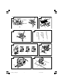 2
2
-
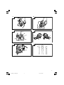 3
3
-
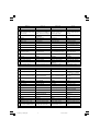 4
4
-
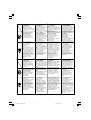 5
5
-
 6
6
-
 7
7
-
 8
8
-
 9
9
-
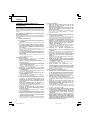 10
10
-
 11
11
-
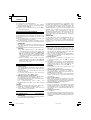 12
12
-
 13
13
-
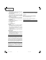 14
14
-
 15
15
-
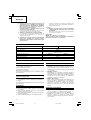 16
16
-
 17
17
-
 18
18
-
 19
19
-
 20
20
-
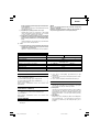 21
21
-
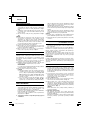 22
22
-
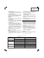 23
23
-
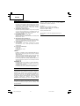 24
24
-
 25
25
-
 26
26
-
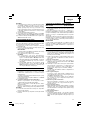 27
27
-
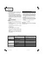 28
28
-
 29
29
-
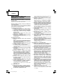 30
30
-
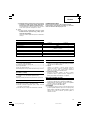 31
31
-
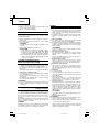 32
32
-
 33
33
-
 34
34
-
 35
35
-
 36
36
-
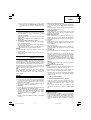 37
37
-
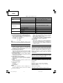 38
38
-
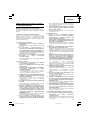 39
39
-
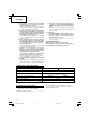 40
40
-
 41
41
-
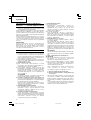 42
42
-
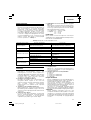 43
43
-
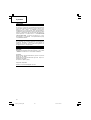 44
44
-
 45
45
-
 46
46
-
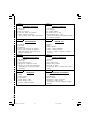 47
47
-
 48
48
-
 49
49
-
 50
50
-
 51
51
-
 52
52


Hikoki FCJ 65S3 Kullanım kılavuzu
- Kategori
- Elektrikli aletler
- Tip
- Kullanım kılavuzu
diğer dillerde
- slovenčina: Hikoki FCJ 65S3 Používateľská príručka
- polski: Hikoki FCJ 65S3 Instrukcja obsługi
İlgili makaleler
Diğer belgeler
-
Hitachi CJ 65S3 Handling Instructions Manual
-
-
-
-
-
Infocus CR 13V Kullanım kılavuzu
-
Hitachi C 8FSE Handling Instructions Manual