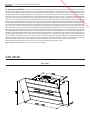
AEG X66453BVO Kullanım kılavuzu
- Kategori
- Ocak davlumbazları
- Tip
- Kullanım kılavuzu
Bu kılavuz aynı zamanda aşağıdakiler için de uygundur:

X66453MVO
X69453MVO
X66453BVO
X69453BVO
Libretto Istruzioni
User Manual
Mode D'emploi
Bedienungsanleitung
Gebruiksaanwijzing
Manual De Instrucciones
Manual De Instruções
Kullanim Kilavuzu
IT
EN
FR
DE
NL
ES
PT
TR
CAPPA
COOKER HOOD
HOTTE DE CUISINE
DUNSTABZUGSHAUBE
AFZUIGKAP
CAMPANA
EXAUSTOR
OCAK DAVLUMBAZ
3
10
17
24
31
38
45
52
Downloaded from www.vandenborre.be

Downloaded from www.vandenborre.be

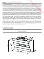
PER RISULTATI PERFETTI
Grazie per aver scelto di acquistare questo prodotto AEG. Lo
abbiamo creato per fornirvi prestazioni impeccabili per molti
anni, grazie a tecnologie innovative che vi semplificheranno
la vita - funzioni che non troverete sui normali elettrodo-
mestici. Vi invitiamo di dedicare qualche minuto alla lettura
per sapere come trarre il massimo dal vostro elettrodomesti-
co.
ACCESSORI E PRODOTTI DI CONSUMO
All'interno del webshop AEG troverete tutto ciò che vi ser-
ve per fare in modo che i vostri elettrodomestici AEG siano
sempre perfettamente puliti e funzionanti. Non mancano
inoltre una vasta gamma di accessori studiati e realizzati
conformemente agli elevati standard qualitativi che vi aspet-
tate: pentole, scolaposate, portabottiglie e sacchi biancheria
delicati...
Visit the webshop at:
www.aeg-electrolux.com/shop
Downloaded from www.vandenborre.be

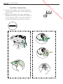
IT - CONSIGLI E SUGGERIMENTI/CARATTERISTICHE
4
IT - CONSIGLI E SUGGERIMENTI - Questo libretto di istruzioni per l'uso è previsto per più versioni dell' apparecchio. É possibile che siano descritti singoli
particolari della dotazione, che non riguardano il Vostro apparecchio. Il produttore declina qualsiasi responsabilità per danni dovuti ad installazione non corretta
o non conforme alle regole dell’arte. La distanza minima di sicurezza tra il Piano di cottura e la Cappa deve essere di 650 mm. Verifi care che la tensione di rete
corrisponda a quella riportata nella targhetta posta all’interno della Cappa. Per Apparecchi in Classe I
a
accertarsi che l’impianto elettrico domestico garantisca un
corretto scarico a terra. Collegare la Cappa all’uscita dell’aria aspirata con tubazione di diametro pari o superiore a 120 mm. Il percorso della tubazione deve essere
il più breve possibile. Non collegare la Cappa a condotti di scarico dei fumi prodotti da combustione (caldaie, caminetti, ecc.). Nel caso in cui nella stanza vengano
utilizzati sia la Cappa che apparecchi non azionati da energia elettrica (ad esempio apparecchi utilizzatori di gas), si deve provvedere ad una aerazione suffi ciente
dell’ambiente. Se la cucina ne fosse sprovvista, praticare un’apertura che comunichi con l’esterno, per garantire il richiamo d’aria pulita. La Cappa è stata progettata
esclusivamente per uso domestico, per abbattere gli odori della cucina. Non fare mai uso improprio della Cappa. Non lasciare fi amme libere a forte intensità sotto la
Cappa in funzione. Regolare sempre le fi amme in modo da evitare una evidente fuoriuscita laterale delle stesse rispetto al fondo delle pentole. Controllare le friggitrici
durante l’uso: l’olio surriscaldato potrebbe infi ammarsi. Non preparare alimenti fl ambè sotto la cappa da cucina; pericolo d'incendio. Questo apparecchio non deve
essere utilizzato da persone (bambini inclusi) con ridotte capacità psichiche, sensoriali o mentali, oppure da persone senza esperienza e conoscenza, a meno che
non siano controllati o istruiti all’uso dell’apparecchio da persone responsabili della loro sicurezza. I bambini devono essere supervisionati per assicurarsi che non
giochino con l’apparecchio. Prima di procedere a qualsiasi operazione di manutenzione, disinserire la Cappa togliendo la spina elettrica o spegnendo l’interruttore
generale. Effettuare una scrupolosa e tempestiva manutenzione dei Filtri secondo gli intervalli consigliati (Rischio di incendio), Filtri antigrasso Z Sono lavabili anche
in lavastoviglie, e necessitano di essere lavati ogni 2 mesi circa di utilizzo o più frequentemente, per un uso particolarmente intenso - Filtri antiodore al Carbone attivo
W Il Filtro antiodore al Carbone attivo non è lavabile e non è rigenerabile, va sostituito ogni 4 mesi circa di utilizzo o più frequentemente, per un uso particolarmente
intenso. Per la pulizia delle superfi ci della Cappa è suffi ciente utilizzare un panno umido e detersivo liquido neutro. Il simbolo
sul prodotto o sulla confezione
indica che il prodotto non deve essere considerato come un normale rifi uto domestico, ma deve essere portato nel punto di raccolta appropriato per il riciclaggio di
apparecchiature elettriche ed elettroniche. Provvedendo a smaltire questo prodotto in modo appropriato, si contribuisce a evitare potenziali conseguenze negative
per l’ambiente e per la salute, che potrebbero derivare da uno smaltimento inadeguato del prodotto. Per informazioni più dettagliate sul riciclaggio di questo prodotto,
contattare l’uffi cio comunale, il servizio locale di smaltimento rifi uti o il negozio in cui è stato acquistato il prodotto.
Collegare la Cappa all’Alimentazione di Rete interponendo un Interruttore bipolare con apertura dei contatti di almeno 3 mm.
Attenzione: Prima di installare la Cappa, togliere le pellicole di protezione (bianca e trasparente).
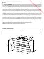
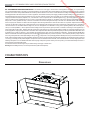
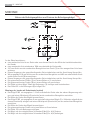
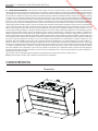
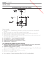
CARATTERISTICHE
Ingombro
Downloaded from www.vandenborre.be

IT - CONSIGLI E SUGGERIMENTI/CARATTERISTICHE
5
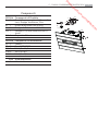
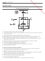
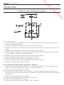
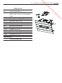
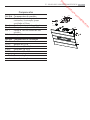
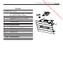
Componenti
Rif. Q.tà Componenti di Prodotto
1 1 Corpo Cappa completo di: Comandi,
Luce, Gruppo Ventilatore, Filtri
8 1 Griglia direzionata Uscita Aria
9 1 Flangia di Riduzione ø 150-120 mm
10 1 Flangia ø 150 con valvola di non ri-
torno
16 1 Coperchio filtrante
Rif. Q.tà Componenti di Installazione
11 2 Tasselli
11a 2 Tasselli SB 12/10
12a 2 Viti 4,2 x 44,4
12c 4 Viti 2,9 x 6,5
12d 2 Viti 2,9 x 9,5
Q.tà Documentazione
1 Libretto Istruzioni
1
11
12a
9
11a
16
12c
12d
8
10
Downloaded from www.vandenborre.be

IT - INSTALLAZIONE
6
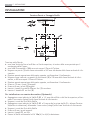
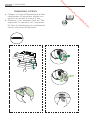
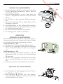
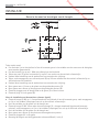
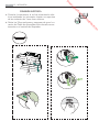
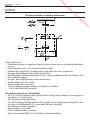
INSTALLAZIONE
Foratura Parete e Fissaggio Staffe
Tracciare sulla Parete:
• una linea Verticale fino al soffitto o al limite superiore, al centro della zona prevista per il
montaggio della Cappa;
• una linea Orizzontale a 1004 mm min. sopra il Piano di Cottura.
• Segnare un punto (1) sulla linea orizzontale a 247 mm alla destra della linea verticale di rife-
rimento.
• Ripetere questa operazione dalla parte opposta, verificandone il livellamento.
• Segnare come indicato, un punto di riferimento (2) a 210 mm dalla linea Verticale di riferi-
mento, e 482 mm sopra il Piano di Cottura.
• Ripetere questa operazione dalla parte opposta, verificandone il livellamento.
• Forare ø 12 mm i punti (1) segnati.
• Forare ø 8 mm i punti (2) segnati.
• Inserire i tasselli con staffa 11a nei fori (1) e avvitare.
• Inserire il tassello 11 nei fori (2).
Per installazione con camino decorativo: (Opzionale)
• Appoggiare come indicato la Staffa 7.2.1 a 1-2 mm dal soffitto o dal limite superiore, alline-
ando il suo centro (intagli) sulla linea Verticale di riferimento.
• Segnare i centri dei Fori della Staffa.
• Appoggiare come indicato la Staffa 7.2.1 a X mm sotto la prima staffa (X = altezza Camino
Superiore in dotazione), allineando il suo centro (intagli) sulla linea Verticale di riferimento.
• Segnare i centri dei Fori della Staffa.
• Forare ø 8 mm i punti segnati.
• Inserire i tasselli 11 nei fori.
• Fissare le Staffe utilizzando le Viti 12a (4,2 x 44,4) in dotazione.
11a
1
1
22
210
11
12a
247 247
1004
482
400
210
X
1÷2
7.2.1
Downloaded from www.vandenborre.be

IT - INSTALLAZIONE
7
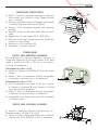
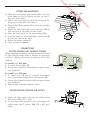
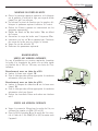
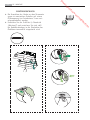
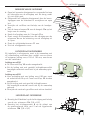
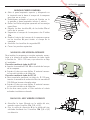
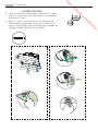
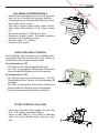
MONTAGGIO CORPO CAPPA
• Aprire il pannello aspirante superiore e bloccarlo
sulla sinistra con l’astina al corpo Cappa affinché
non si richiuda.
• Sbloccare togliendo il perno di fissaggio sulla sinistra
il pannello aspirante inferiore ed aprirlo.
• Togliere i Filtri Antigrasso agendo sulle apposite
maniglie.
• Regolare le due viti Vr, delle staffe 11a, ad inizio
corsa.
• Agganciare il corpo cappa alle 2 staffe 11a.
• Dall’interno del corpo cappa agire sulle Viti Vr per
livellare il Corpo Cappa.
• Avvitare le viti di sicurezza 11.
• Richiudere i pannelli aspiranti.
CONNESSIONI
USCITA ARIA VERSIONE ASPIRANTE
Per installazione in Versione Aspirante collegare la
Cappa alla tubazione di uscita per mezzo di un tubo
rigido o flessibile di ø150 o 120 mm, la cui scelta è
la-sciata all'installatore.
Collegamento tubo ø 150
• Inserire la Flangia ø 150 10 sull’Uscita del Corpo
Cappa.
• Fissare il tubo con adeguate fascette stringitubo.
Il materiale occorrente non è in dotazione.
Collegamento tubo ø 120
• Per collegamento con tubo ø120 mm, inserire
la Flangia di riduzione 9 sulla flangia ø 150 10
prece-dentemente installata.
• Fissare il tubo con adeguate fascette stringitubo.
Il materiale occorrente non è in dotazione.
• In ambedue i casi, togliere eventuali Filtri Antiodore
al Carbone attivo.
USCITA ARIA VERSIONE FILTRANTE
• Avvitare il coperchio filtrante sull’uscita aria, uti-
lizzando quattro viti 12c (2,9 x 6,5).
• Fissare la Griglia direzionata 8 sull’uscita dell’aria
riciclata con 2 Viti 12d (2,9 x 9,5) in dotazione.
ø 120
ø 150
10
10
9
Vr
11
11a
16
12c
12d
8
Downloaded from www.vandenborre.be

IT - INSTALLAZIONE
8
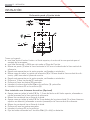
CONNESSIONE ELETTRICA
• Collegare la Cappa all’Alimentazione di Rete
interponendo un Interruttore bipolare con
apertura dei contatti di almeno 3 mm.
• Rimuovere i Filtri antigrasso (vedi par. “Ma-
nutenzione”) e assicurarsi che il connettore
del Cavo di alimentazione sia correttamente
inserito nella presa dell’Aspiratore
Downloaded from www.vandenborre.be

IT - USO
9
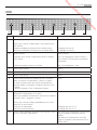
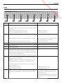
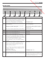
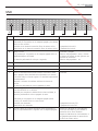
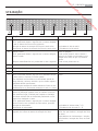
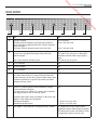
Tasto Funzione Led
A
Accende e spegne l’impianto di illuminazione.
Premuto per 5 Secondi a Cappa spenta e senza allarmi filtri in
corso effettua:
Attivazione dell’allarme saturazione Filtri al Carbone Attivo.
Disattivazione dell’allarme saturazione Filtri al Carbone Attivo.
Acceso o Spento.
2 Lampeggi Led tasto H.
1 Lampeggio Led tasto H.
B
Spegne il Motore.
Se premuto per 5 Secondi a Cappa spenta Attiva la modalità
Blocco Tastiera.
Si disattiva premendo il tasto per 5 Secondi.
Acceso o Spento.
Tutti i Led Lampeggiano 2 Volte e durante il
Blocco Tastiera i Led ese-guono una sequenza
di accensione.
Tutti i Led Lampeggiano 1 Volta
C
Attiva la prima velocità. Acceso.
D
Attiva la seconda velocità. Acceso.
E
Attiva la terza velocità. Acceso.
F
Attiva la velocità intensiva da qualsiasi velocità o da motore
spento, tale velocità è temporizzata a 5 minuti, al termine
del tempo il sistema ritorna alla velocità precedentemente
impostata. Adatta a fronteggiare le massime emissioni di fumi
di cottura.
Si Disattiva premendo il Tasto o Spegnendo il Motore.
Acceso.
G
Attiva lo spegnimento automatico ritardato del Motore e
dell’Impianto di Illuminazione di 15 minuti.
Adatto per completare l’eliminazione di odori residui, si disattiva
premendo il tasto o spegnendo il motore.
Premuto per 5 Secondi a Cappa spenta(Motore+Luci) e senza
allarmi filtri in corso effettua:
Attivazione del Telecomando.
Disattivazione del Telecomando.
Acceso.
2 Lampeggi Led tasto C + B
1 Lampeggi Led tasto C + B
H
Effettua il Reset dell’allarme saturazione Filtri premendo il Tasto
per circa 2 Secondi a Cappa Spenta.
Dopo 100 ore di Funzionamento il Led è Acceso
Fisso per segnalare la saturazione dei Filtri
Metallici.
Dopo 200 ore di Funzionamento il Led Lam-
peggia per segnalare la saturazione dei Filtri al
Carbone Attivo.
A
B
C D
E
F
G H
USO
Downloaded from www.vandenborre.be

FOR PERFECT RESULTS
Thank you for choosing this AEG product. We have created
it to give you impeccable performance for many years, with
innovative technologies that help make life simpler – fea-
tures you might not find on ordinary appliances. Please
spend a few minutes reading to get the very best from it.
ACCESSORIES AND CONSUMABLES
In the AEG webshop, you’ll find everything you need to keep
all your AEG appliances looking spotless and working per-
fectly. Along with a wide range of accessories designed and
built to the high quality standards you would expect, from
specialist cookware to cutlery baskets, from bottle holders to
delicate laundry bags…
Visit the webshop at:
www.aeg-electrolux.com/shop
Downloaded from www.vandenborre.be

EN - RECOMMENDATIONS AND SUGGESTIONS/CHARACTERISTICS
11
EN - RECOMMENDATIONS AND SUGGESTIONS - The Instructions for Use apply to several versions of this appliance. Accordingly, you may fi nd descrip-
tions of individual features that do not apply to your specifi c appliance. The manufacturer will not be held liable for any damages resulting from incorrect or improper
installation. The minimum safety distance between the cooker top and the extractor hood is 650 mm. Check that the mains voltage corresponds to that indicated on
the rating plate fi xed to the inside of the hood. For Class I appliances, check that the domestic power supply guarantees adequate earthing. Connect the extractor to
the exhaust fl ue through a pipe of minimum diameter 120 mm. The route of the fl ue must be as short as possible. Do not connect the extractor hood to exhaust ducts
carrying combustion fumes (boilers, fi replaces, etc.). If the extractor is used in conjunction with non electrical appliances (e.g. gas burning appliances), a suffi cient
degree of aeration must be guaranteed in the room in order to prevent the backfl ow of exhaust gas. The kitchen must have an opening communicating directly with
the open air in order to guarantee the entry of clean air. The extractor hood has been designed exclusively for domestic use to eliminate kitchen smells. Never use
the hood for purposes other than for which it has been designed. Never leave high naked fl ames under the hood when it is in operation. Adjust the fl ame intensity
to direct it onto the bottom of the pan only, making sure that it does not engulf the sides. Deep fat fryers must be continuously monitored during use: overheated oil
can burst into fl ames. Do not fl ambè under the range hood; risk of fi re This appliance is not intended for use by persons (including children) with reduced physical,
sensory or mental capabilities, or lack of experience and knowledge, unless they have been given supervision or instruction concerning use of the appliance by a
person responsible for their safety. Children should be supervised to ensure that they do not play with the appliance. Switch off or unplug the appliance from the
mains supply before carrying out any maintenance work.Clean and/or replace the Filters after the specifi ed time period (Fire hazard), Grease fi lters Z The fi lters must
be cleaned every 2 months of operation, or more frequently for particularly heavy usage, and can be washed in a dishwasher. - Activated charcoal fi lter W These
fi lters are not washable and cannot be regenerated, and must be replaced approximately every 4 months of operation, or more frequently with heavy usage. Clean the
hood using a damp cloth and a neutral liquid detergent. The symbol
on the product or on its packaging indicates that this product may not be treated as household
waste. Instead it shall be handed over to the applicable collection point for the recycling of electrical and electronic equipment. By ensuring this product is disposed
of correctly, you will help prevent potential negative consequences for the environment and human health, which could otherwise be caused by inappropriate waste
handling of this product. For more detailed information about recycling of this product, please contact your local city offi ce, your household waste disposal service or
the shop where you purchased the product.
Connect the hood to the mains through a two-pole switch having a contact gap of at least 3 mm.
Warning: Before installing the Hood, remove the protective fi lms (white and transparent).
CHARACTERISTICS
Dimensions
Downloaded from www.vandenborre.be

EN - RECOMMENDATIONS AND SUGGESTIONS/CHARACTERISTICS
12
Components
Ref. Q.ty Product Components
1 1 Hood Body, complete with: Controls,
Light, Blower, Filters
8 1 Directional Air Outlet grille
9 1 Reducer Flange ø 150-120 mm
10 1 Dumper
16 1 Filter cover
Ref. Q.ty Installation Components
11 2 Wall Plugs
11a 2 Wall Plugs SB 12/10
12a 2 Screws 4,2 x 44,4
12c 4 Screws 2,9 x 6,5
12d 2 Screws 2,9 x 9,5
Q.ty Documentation
1 Instruction Manual
1
11
12a
9
11a
16
12c
12d
8
10
Downloaded from www.vandenborre.be

EN - INSTALLATION
13
INSTALLATION
Wall drilling and bracket fixing
As a first step, proceed with the following drawings:
• a vertical line up to the ceiling or up to the upper limit, at the centre of the area in which the
hood is to be fitted;
• a horizontal line at a minimum 1004 mm above the cooker top.
• Mark a point (1) on the horizontal line, 247 mm to the right of the vertical reference line.
• Repeat this operation on the other side, checking that the two marks are levelled.
• Mark a reference point (2) as indicated at 210 mm from the vertical reference line and 482
mm above the cooker top.
• Repeat this operation on the other side, checking that the two marks are levelled.
• Drill at the marked points (1), using a ø 12 mm drill bit.
• Drill at the marked points (2) using a ø 8 mm drill bit.
• Insert the bracket plugs 11a into the holes (1) and tighten the screws.
• Insert plug 11 into holes (2).
To install a decorative chimney ( optional )
• Place bracket 7.2.1 on the wall, about 1-2 mm from the ceiling or from the upper limit,
aligning the centre (notch) with the vertical reference line.
• Mark the wall at the centres of the bracket holes.
• Place the bracket 7.2.1 on the wall at X mm below the first bracket (X = height of the upper
chimney section), aligning the centre (notch) with the vertical line.
• Mark the wall at the centres of the bracket holes.
• Drill ø 8 mm holes at all the marked centre points.
• Insert the wall plugs 11 in the holes.
• Fix the brackets using the 12a screws (4,2 x 44,4) supplied with the hood.
11a
1
1
22
210
11
12a
247 247
1004
482
400
210
X
1÷2
7.2.1
Downloaded from www.vandenborre.be

EN - INSTALLATION
14
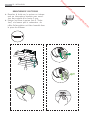
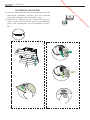
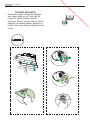
FITTING THE HOOD BODY
• Open the top suction panel and fasten it to the
hood body on the left using the pin, so that it
does not close again.
• Unlock the lower suction panel by removing the
fixing pin on the left, and open it.
• Remove the Metal grease filters using the handles
provided.
• Adjust the two screws Vr, in the brackets 11a, so
that they are at the start of their travel.
• Hook the hood body to the two brackets 11a.
• From the inside of the hood body, turn screws Vr
to level the hood body itself.
• Fasten the safety screws 11.
• Close the suction panels.
CONNECTIONS
DUCTED VERSION AIR EXHAUST SYSTEM
When installing the ducted version, connect the hood
to the chimney using either a flexible or rigid pipe
ø 150 or 120mm, the choice of which is left to the
installer.
To install a ø 150 pipe
• To install the dumper 10
• Fix the pipe in position using sufficient pipe clamps
(not supplied).
To install a ø 120 pipe
• To install a ø 120 mm air exhaust connection,
insert the reducer flange 9 on the dumper 10.
• Fix the pipe in position using sufficient pipe clamps
(not supplied).
• Remove any activated charcoal filters.
RECIRCULATION VERSION AIR OUTLET
.
• Screw the filter cover onto the air outlet, using
four screws 12c (2.9 x 12.5).
• Fix the directional grille 8 on the recirculation air
outlet using the 2 screws 12d (2,9 x 9,5) pro-
vided.
ø 120
ø 150
10
10
9
Vr
11
11a
16
12c
12d
8
Downloaded from www.vandenborre.be

EN - INSTALLATION
15
ELECTRICAL CONNECTION
• Connect the hood to the mains through a
two-pole switch having a contact gap of at
least 3 mm.
• Remove the grease filters (see paragraph
Maintenance) being sure that the connector
of the feeding cable is correctly inserted in
the socket placed on the side of the fan.
Downloaded from www.vandenborre.be

EN - USE
16
A
B
C D
E
F
G H
USE
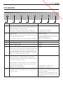
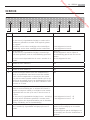
Button Function Led
A
Turns the Lighting System on and off.
If pressed and held for 5 seconds with the hood turned off and
no alarm, do:
Enables the Activated Charcoal Filter Alarm.
Disables the Activated Charcoal Filter Alarm.
On or Off
2 Flashes Led buttom H
1 Flash Led buttom H
B
Turns the Motor on and off.
Enables Keyboard Lock mode if pressed and held for 5 seconds.
It is disabled by pressing the button for 5 seconds.
On or Off
All the Leds flash twice and during Keyboard
Lock the Leds light up in sequence.
All the Leds flash once.
C
Activates speed one. On.
D
Activates speed two. On.
E
Activates speed three. On.
F
Activates intensive speed from any other speed, including motor
off. This speed is timed to run for 5 minutes, after which the
system will return to the speed that was previously set. Suitable
to deal with se-vere cooking fumes.
It is deactivated by pressing the button or turning the motor off.
On.
G
Activates delayed automatic shutdown of the motor and the
lighting system after 15 minuts.
Suitable to complete the elimination of residual odours, it is
deactivated by press-ing the button of turning the motor off.
If pressed and held for 5 seconds with the hood and lightturned
off and no alarm, do:
Enables the Remote control.
Disables the Remote control.
On.
2 Flashes Led buttom C + B
1 Flash Led buttom C + B
H
Performs a Reset of the Filter saturation alarm when the button
is pressed for ap-proximately 2 seconds with the hood turned
off.
After 100 hours operation the Led lights up
continuously to indicate saturation of the
Metal Grease Filters.
After 200 hours operation the Led flashes to
indicate saturation of the Activated Charcoal
Filters.
Downloaded from www.vandenborre.be

POUR DES RÉSULTATS PARFAITS
Merci d'avoir choisi ce produit AEG. Nous l'avons créé
pour vous offrir la meilleure performance pour une lon-
gue durée, avec des technologies innovantes qui vous
simplifient la vie - autant de caractéristiques que vous
ne trouverez pas sûrement pas sur d'autres appareils.
Veuillez prendre quelques instants pour lire cette notice
afin d'utiliser au mieux votre appareil.
ACCESSOIRES ET CONSOMMABLES
Dans la boutique en ligne d'AEG, vous trouverez tout ce
qu'il vous faut pour que vos appareils AEG fonctionnent
parfaitement. Sans oublier une vaste gamme d'accessoi-
res conçus et fabriqués selon les critères de qualité les
plus élevés qui soient, des articles de cuisine spécialisés
aux range-couverts, des porte-bouteilles aux sacs à linge
délicats...
Visit the webshop at:
www.aeg-electrolux.com/shop
Downloaded from www.vandenborre.be

FR - CONSEILS ET SUGGESTIONS/CARACTERISTIQUES
18
FR - CONSEILS ET SUGGESTIONS - La présente notice d’emploi vaut pour plusieurs versions de l’appareil. Elle peut contenir des descriptions d’accessoires
ne fi gurant pas dans votre appareil. Le fabricant décline toute responsabilité en cas de dommage dû à une installation non correcte ou non conforme aux règles
de l’art. La distance minimale de sécurité entre le plan de cuisson et la hotte doit être de 650 mm au moins. Vérifi er que la tension du secteur correspond à la
valeur qui fi gure sur la plaquette apposée à l’intérieur de la hotte. Pour les Appareils appartenant à l
a
Ière Classe, veiller à ce que la mise à la terre de l’installation
électrique domestique ait été effectuée conformément aux normes en vigueur. Connecter la hotte à la sortie d’air aspiré à l’aide d’une tuyauterie d’un diamètre égal
ou supérieur à 120 mm. Le parcours de la tuyauterie doit être le plus court possible. Ne pas connecter la hotte à des conduites d’évacuation de fumées issues
d’une combustion tel que (Chaudière, cheminée, etc…). Si vous utilisez des appareils qui ne fonctionnent pas à l’électricité dans la pièce ou est installée la hotte
(par exemple: des appareils fonctionnant au gaz), vous devez prévoir une aération suffi sante du milieu. Si la cuisine en est dépourvue, pratiquez une ouverture qui
communique avec l’extérieur pour garantir l’infi ltration de l’air pur. La hotte a été conçue exclusivement pour l’usage domestique, dans le but d’éliminer les odeurs
de la cuisine. Ne jamais utiliser abusivement la hotte. Ne pas laisser les fl ammes libres à forte intensité quand la hotte est en service. Toujours régler les fl ammes
de manière à éviter toute sortie latérale de ces dernières par rapport au fond des marmites. Contrôler les friteuses lors de l’utilisation car l’huile surchauffée pourrait
s’enfl ammer. Ne pas préparer d’aliments fl ambés sous la hotte de cuisine : risque d’incendie Cet appareil ne doit pas être utilisé par des personnes (y compris
les enfants) ayant des capacités psychiques, sensorielles ou mentales réduites, ni par des personnes n’ayant pas l’expérience et la connaissance de ce type
d’appareils, à moins d’être sous le contrôle et la formation de personnes responsables de leur sécurité. Les enfants doivent être surveillés pour s’assurer qu’ils
ne jouent pas avec l’appareil. Avant de procéder à toute opération d’entretien, retirer la hotte en retirant la fi che ou en actionnant l’interrupteur général. Effectuer
un entretien scrupuleux et en temps dû des Filtres, à la cadence conseillée (Risque d’incendie), Filtres anti-graisse Z Lavables au lave-vaisselle, ils doivent être
lavés environ tous les 2 mois d’emploi ou plus fréquemment en cas d’emploi particulièrement intense. - Filtre anti-odeur W Il ne sont pas lavables ni régénérables,
il faut les remplacer au moins tous les 4 mois d’emploi ou plus fréquemment en cas d’emploi particulièrement intense. Pour le nettoyage des surfaces de la hotte,
il suffi t d’utiliser un chiffon humide et détersif liquide neutre. Le symbole
sur le produit ou son emballage indique que ce produit ne peut être traité comme
déchet ménager. Il doit plutôt être remis au point de ramassage concerné, se chargeant du recyclage du matériel électrique et électronique. En vous assurant que
ce produit est éliminé correctement, vous favorisez la prévention des conséquences négatives pour l’environnement et la santé humaine qui, sinon, seraient le
résultat d’un traitement inapproprié des déchets de ce produit. Pour obtenir plus de détails sur le recyclage de ce produit, veuillez prendre contact avec le bureau
muni-cipal de votre région, votre service d’élimination des déchets ménagers ou le magasin où vous avez acheté le produit.
Brancher la hotte sur le secteur en interposant un interrupteur bipolaire avec ouverture des contacts d’au moins 3 mm.
Attention : Retirez les fi lms de protection (blanc et transparent) avant d’installer la hotte.
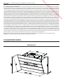
CARACTERISTIQUES
Encombrement
Downloaded from www.vandenborre.be

FR - CONSEILS ET SUGGESTIONS/CARACTERISTIQUES
19
Composants
Réf. Q.té Composants de Produit
1 1 Corps Hotte équipé de:Comandes, Lu-
mière, Groupe Ventilateur, Filtres
8 1 Grille orientée Sortie de l’Air
9 1 Flasque de Réduction ø 150-120 mm
10 1 Buse avec clapet ø150
16 1 Couvercle filtrant
Réf. Q.té Composants pour l ’installation
11 2 Chevilles
11a 2 Chevilles SB 12/10
12a 2 Vis 4,2 x 44,4
12c 4 Vis 2,9 x 6,5
12d 2 Vis 2,9 x 9,5
Q.té Documentation
1 Manuel d’instructions
1
11
12a
9
11a
16
12c
12d
8
10
Downloaded from www.vandenborre.be

FR - INSTALLATION
20
INSTALLATION
Perçage de la paroi et fixation des supports
Tracer sur la paroi :
• une ligne verticale jusqu’au plafond ou à la limite supérieure, au centre de la zone prévue
pour le montage de la hotte ;
• une ligne horizontale à 1004 mm au-dessus du plan de cuisson.
• Marquer un point (1) sur la ligne horizontale à 247 mm à droite de la ligne verticale de réfé-
rence.
• Répéter cette opération de l’autre côté et vérifier la mise à niveau.
• Marquer comme indiqué, un point de référence (2) à 210 mm de la ligne verticale de réfé-
rence et 482 mm au-dessus du plan de cuisson.
• Répéter cette opération de l’autre côté et vérifier la mise à niveau.
• Percer les points marqués (1) avec une mèche de ø 12 mm.
• Percer les points marqués (2) avec une mèche de ø 8 mm.
• Mettre les chevilles avec le support 11a dans les trous (1) et visser.
• Insérer les chevilles 11 dans les trous (2).
Pour installation avec cheminée décorative : (Option)
• Poser le support 7.2.1 comme indiqué, à 1-2 mm du plafond ou de la limite supérieure, en
alignant le centre (encoches) sur la ligne verticale de référence.
• Marquer les centres des trous du support.
• Faire reposer le support 7.2.1, comme indiqué, à X mm en dessous du premier support (X =
hauteur de la partie supérieure fournie), en alignant le centre (encoches) sur la ligne verticale
de référence.
• Marquer les centres des trous du support.
• Percer les points marqués avec une mèche de ø 8 mm.
• Insérer les chevilles 11 dans les trous.
• Fixer les supports à l’aide des vis 12a (4,2 x 44,4) fournies.
11a
1
1
22
210
11
12a
247 247
1004
482
400
210
X
1÷2
7.2.1
Downloaded from www.vandenborre.be
Sayfa yükleniyor...
Sayfa yükleniyor...
Sayfa yükleniyor...
Sayfa yükleniyor...
Sayfa yükleniyor...
Sayfa yükleniyor...
Sayfa yükleniyor...
Sayfa yükleniyor...
Sayfa yükleniyor...
Sayfa yükleniyor...
Sayfa yükleniyor...
Sayfa yükleniyor...
Sayfa yükleniyor...
Sayfa yükleniyor...
Sayfa yükleniyor...
Sayfa yükleniyor...
Sayfa yükleniyor...
Sayfa yükleniyor...
Sayfa yükleniyor...
Sayfa yükleniyor...
Sayfa yükleniyor...
Sayfa yükleniyor...
Sayfa yükleniyor...
Sayfa yükleniyor...
Sayfa yükleniyor...
Sayfa yükleniyor...
Sayfa yükleniyor...
Sayfa yükleniyor...
Sayfa yükleniyor...
Sayfa yükleniyor...
Sayfa yükleniyor...
Sayfa yükleniyor...
Sayfa yükleniyor...
Sayfa yükleniyor...
Sayfa yükleniyor...
Sayfa yükleniyor...
Sayfa yükleniyor...
Sayfa yükleniyor...
Sayfa yükleniyor...
Sayfa yükleniyor...
-
 1
1
-
 2
2
-
 3
3
-
 4
4
-
 5
5
-
 6
6
-
 7
7
-
 8
8
-
 9
9
-
 10
10
-
 11
11
-
 12
12
-
 13
13
-
 14
14
-
 15
15
-
 16
16
-
 17
17
-
 18
18
-
 19
19
-
 20
20
-
 21
21
-
 22
22
-
 23
23
-
 24
24
-
 25
25
-
 26
26
-
 27
27
-
 28
28
-
 29
29
-
 30
30
-
 31
31
-
 32
32
-
 33
33
-
 34
34
-
 35
35
-
 36
36
-
 37
37
-
 38
38
-
 39
39
-
 40
40
-
 41
41
-
 42
42
-
 43
43
-
 44
44
-
 45
45
-
 46
46
-
 47
47
-
 48
48
-
 49
49
-
 50
50
-
 51
51
-
 52
52
-
 53
53
-
 54
54
-
 55
55
-
 56
56
-
 57
57
-
 58
58
-
 59
59
-
 60
60


AEG X66453BVO Kullanım kılavuzu
- Kategori
- Ocak davlumbazları
- Tip
- Kullanım kılavuzu
- Bu kılavuz aynı zamanda aşağıdakiler için de uygundur:
diğer dillerde
- español: AEG X66453BVO Manual de usuario
- français: AEG X66453BVO Manuel utilisateur
- italiano: AEG X66453BVO Manuale utente
- Deutsch: AEG X66453BVO Benutzerhandbuch
- português: AEG X66453BVO Manual do usuário
- English: AEG X66453BVO User manual
- Nederlands: AEG X66453BVO Handleiding
İlgili makaleler
Diğer belgeler
-
 Franke Consumer Products FPL 606 Kullanım kılavuzu
-
Aeg-Electrolux X99384MV0 Kullanım kılavuzu
-
 Franke Consumer Products FCR 708-H TC Kullanım kılavuzu
-
Franke FTMY AH BK MATT F90 Hood Kullanım kılavuzu
-
 Franke Consumer Products Indoor Furnishings FQD 907 Kullanım kılavuzu
-
Teka DVF 67670 TBS WH Kullanım kılavuzu
-
Electrolux EFC6540X Kullanım kılavuzu
-
V-ZUG 6400260003 Kullanım kılavuzu
-
 Franke Consumer Products FMY 907 Kullanım kılavuzu
-
 Franke Consumer Products FCH 906 Kullanım kılavuzu


