
DOC023.97.80570
9525sc DCCP System
10/2020, Edition 6
User Manual
Bedienungsanleitung
Manuale utente
Manuel de l'utilisateur
Manual del usuario
Brugervejledning
Kullanıcı Kılavuzu
Εγχειρίδιο χρήσης

Table of Contents
English..............................................................................................................................3
Deutsch.......................................................................................................................... 30
Italiano............................................................................................................................ 58
Français......................................................................................................................... 86
Español........................................................................................................................ 114
Dansk............................................................................................................................142
Türkçe...........................................................................................................................169
Ελληνικά...................................................................................................................... 196
2

Table of Contents
1 Specifications on page 3
2 General information on page 4
3 Installation on page 10
4 Startup on page 17
5 User interface and navigation on page 18
6 Operation on page 20
7 Advanced operation on page 21
8 Maintenance on page 22
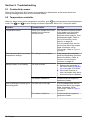
9 Troubleshooting on page 28
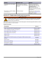
10 Replacement parts and accessories
on page 29
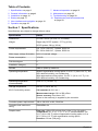
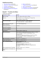
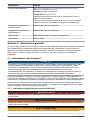
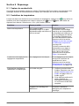
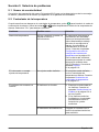
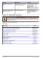
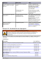
Section 1 Specifications
Specifications are subject to change without notice.
Specification Details
Dimensions 91 x 62 x 38 cm (36 x 24.5 x 15 inches)
Weight Degas-only DCCP system : 27.7 kg (61 lb)
DCCP system: 50 kg (110 lb)
Power requirements US: 110 to 120 VAC, 1 phase, 50/60 Hz
EU: 220 to 240 VAC, 1 phase, 50/60 Hz
Main supply voltage fluctuation ±10% of nominal voltage
Power consumption 1.6 kVA
Pollution degree 2
Installation category II
Altitude 2000 m (6562 ft) maximum
Operating temperature Without regenerative cooling option: 2 to 50 °C (36 to 122 °F), 0 to
85% relative humidity, non-condensing
With regenerative cooling option: 2 to 45 °C (36 to 113 °F), 0 to
85% relative humidity, non-condensing
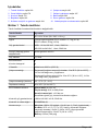
Operating temperature
(recommended)
23 to 27 °C (73 to 81 °F)
Storage temperature 0 to 50 °C (32 to 122 °F)
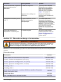
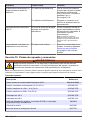
8315 Conductivity sensor Cell constant, k: 0.01 cm
-1
Measurement range: 0.01 to 200 μS/cm
Sensor accuracy: less than ± 2%
Power to the sensor(s) is supplied by the controller.
Controller power requirements 100 to 240 VAC ±10%, 50/60 Hz
Controller and instrument
rating
IP66/NEMA 4X
Sample water Flow rate: 100 to 150 mL/min; 6 to 9 L/hr (1.5 to 2.4 gal/hr)
Temperature: 25 °C ± 1 °C (77 °F ± 2 °F) recommended; 2 to
54 °C (36 to 129 °F) without regenerative cooling option or 2 to
45 °C (36 to 113 °F) with regenerative cooling option
Pressure: 6.9 bar (100 psig)
English 3

Specification Details
Cooling water
Note: Cooling water is not used if the instrument has the regenerative cooling option.
Flow rate: 0.8 L/min (0.2 gal/min)
Temperature: 22 °C (71.6 °F)
Use clean water with no suspended solids and a low hardness.
Use water that is low in chlorides. Chlorides can cause corrosion
in the stainless steel coil and shell.
Sample water connections ¼-inch tube fittings
Cooling water connections ¼-inch tube fittings
Flow cell ¾-inch FNPT, 316 stainless steel
Certifications CE, UL, CSA
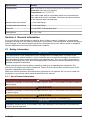
Section 2 General information
In no event will the manufacturer be liable for direct, indirect, special, incidental or consequential
damages resulting from any defect or omission in this manual. The manufacturer reserves the right to
make changes in this manual and the products it describes at any time, without notice or obligation.
Revised editions are found on the manufacturer’s website.
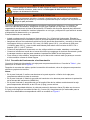
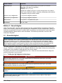
2.1 Safety information
N O T I C E
The manufacturer is not responsible for any damages due to misapplication or misuse of this
product including, without limitation, direct, incidental and consequential damages, and disclaims
such damages to the full extent permitted under applicable law. The user is solely responsible to
identify critical application risks and install appropriate mechanisms to protect processes during a
possible equipment malfunction.
Please read this entire manual before unpacking, setting up or operating this equipment. Pay
attention to all danger and caution statements. Failure to do so could result in serious injury to the
operator or damage to the equipment.
Make sure that the protection provided by this equipment is not impaired. Do not use or install this
equipment in any manner other than that specified in this manual.
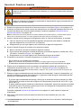
2.1.1 Use of hazard information
D A N G E R
Indicates a potentially or imminently hazardous situation which, if not avoided, will result in death or
serious injury.
W A R N I N G
Indicates a potentially or imminently hazardous situation which, if not avoided, could result in death
or serious injury.
C A U T I O N
Indicates a potentially hazardous situation that may result in minor or moderate injury.
N O T I C E
Indicates a situation which, if not avoided, may cause damage to the instrument. Information that
requires special emphasis.
4 English

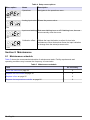
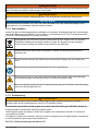
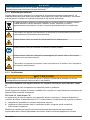
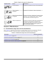
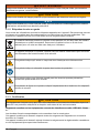
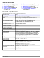
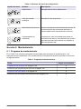
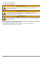
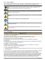
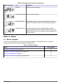
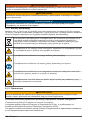
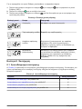
2.1.2 Precautionary labels
Read all labels and tags attached to the instrument. Personal injury or damage to the instrument
could occur if not observed. A symbol on the instrument is referenced in the manual with a
precautionary statement.
Electrical equipment marked with this symbol may not be disposed of in European
domestic or public disposal systems. Return old or end-of-life equipment to the
manufacturer for disposal at no charge to the user.
This symbol, if noted on the instrument, references the instruction manual for operation
and/or safety information.
This symbol indicates that a risk of electrical shock and/or electrocution exists.
This symbol indicates the need for protective eye wear.
This symbol indicates that the marked item can be hot and should not be touched without
care.
This symbol, when noted on the product, identifies the location of a fuse or current
limiting device.
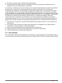
2.1.3 Certification
C A U T I O N
This equipment is not intended for use in residential environments and may not provide adequate
protection to radio reception in such environments.
Canadian Radio Interference-Causing Equipment Regulation, ICES-003, Class A:
Supporting test records reside with the manufacturer.
This Class A digital apparatus meets all requirements of the Canadian Interference-Causing
Equipment Regulations.
Cet appareil numérique de classe A répond à toutes les exigences de la réglementation canadienne
sur les équipements provoquant des interférences.
FCC Part 15, Class "A" Limits
Supporting test records reside with the manufacturer. The device complies with Part 15 of the FCC
Rules. Operation is subject to the following conditions:
1. The equipment may not cause harmful interference.
2. The equipment must accept any interference received, including interference that may cause
undesired operation.
Changes or modifications to this equipment not expressly approved by the party responsible for
compliance could void the user's authority to operate the equipment. This equipment has been tested
and found to comply with the limits for a Class A digital device, pursuant to Part 15 of the FCC rules.
These limits are designed to provide reasonable protection against harmful interference when the
equipment is operated in a commercial environment. This equipment generates, uses and can
radiate radio frequency energy and, if not installed and used in accordance with the instruction
English
5

manual, may cause harmful interference to radio communications. Operation of this equipment in a
residential area is likely to cause harmful interference, in which case the user will be required to
correct the interference at their expense. The following techniques can be used to reduce
interference problems:
1. Disconnect the equipment from its power source to verify that it is or is not the source of the
interference.
2. If the equipment is connected to the same outlet as the device experiencing interference, connect
the equipment to a different outlet.
3. Move the equipment away from the device receiving the interference.
4. Reposition the receiving antenna for the device receiving the interference.
5. Try combinations of the above.
2.2 Intended use
The 9525sc DCCP System is intended for use by individuals who measure water quality parameters
in a sample stream of high purity water. The 9525sc DCCP System does not treat or alter water.
6 English

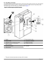
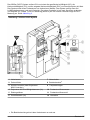
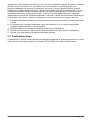
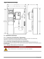
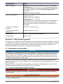
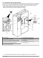
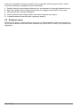
2.3 Product overview
The 9525sc degas-only DCCP (degas cation conductivity panel) system removes CO
2
and measures
degassed cation conductivity (DCC). The system measures a sample stream of high purity water.
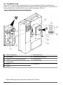
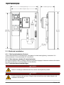
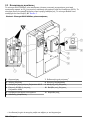
The system has one sensor and one controller. Refer to Figure 1.
Figure 1 9525sc degas-only DCCP system
1 Heater 7 Power indicator light
1
2 Sample cooler 8 Temperature controller
3 Polymetron 8315 conductivity sensor 9 Sample flow meter
4 SC200 Controller (or Polymetron
9500 controller)
10 Sample flow valve
5 Electrical enclosure 11 Flow cell
6 Power switch
1
The power indicator light starts and stops with the heater.
English 7

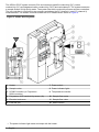
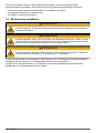
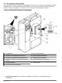
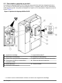
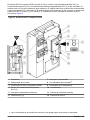
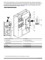
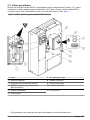
The 9525sc DCCP system removes CO
2
and measures specific conductivity (SC), cation
conductivity (CC) and degassed cation conductivity (DCC) and calculates pH. The system measures
a sample stream of high purity water. The system has three conductivity sensors and two controllers.
The top controller is connected to two sensors and shows the SC (channel 1) and CC (channel 2)
measurements. The bottom controller shows the DCC measurement. Refer to Figure 2.
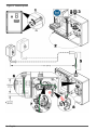
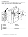
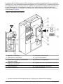
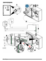
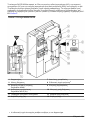
Figure 2 9525sc DCCP system
1 Heater 7 Power switch
2 Sample cooler 8 Power indicator light
2
3 SC200 Controller (or Polymetron
9500 controller)
9 Temperature controller
4 Polymetron 8315 conductivity sensor (3x) 10 Sample flow meter
5 Electrical enclosure 11 Sample flow valve
6 Flow cell (3x) 12 Resin column
2
The power indicator light starts and stops with the heater.
8 English

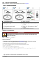
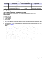
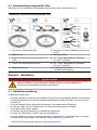
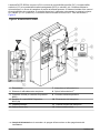
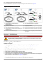
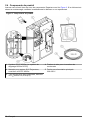
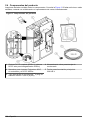
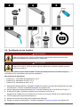
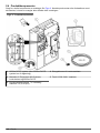
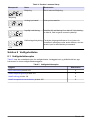
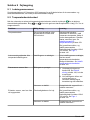
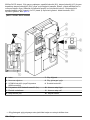
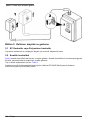
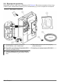
2.4 Product components
Make sure that all components have been received. Refer to Figure 3. If any items are missing or
damaged, contact the manufacturer or a sales representative immediately.
Figure 3 Product components
1 9525sc DCCP system (or 9525sc degas-only
DCCP system)
4 Tubing clamp for condensate drain
2 Manuals for Polymetron 8315 sensor,
controller and 9525sc DCCP
5 Ferrite for 220–240 V main power
3 Condensate drain tubing,
3
/
8
-inch ID x
2.44 m (8 ft)
English 9

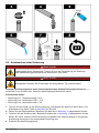
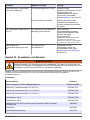
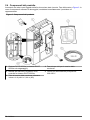
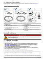
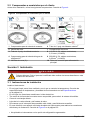
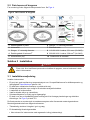
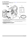
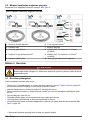
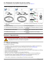
2.5 Customer-supplied parts
Before installation, collect the components that follow. Refer to Figure 4.
Figure 4 Customer-supplied parts
1 Sample plumbing parts 6 Tubing, ¼-inch OD
3
2 Shutoff valve 7 Electrical parts
3 Tubing, ¼-inch OD 8 110/120 VAC: Wire conductors, 3.31 mm
2
(12 AWG)
4 Cooling water plumbing parts
3
9 220/240 VAC: Wire conductors, 2.08 mm
2
(14 AWG)
5 Shutoff valves (2x)
3
10 Conduit fitting for main power
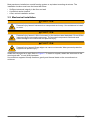
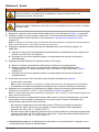
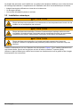
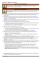
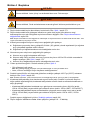
Section 3 Installation
D A N G E R
Multiple hazards. Only qualified personnel must conduct the tasks described in this
section of the document.
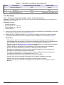
3.1 Installation guidelines
Install the instrument:
• In a clean, dry, well-ventilated and temperature-controlled location. Refer to the operating
temperature and humidity specifications in Specifications on page 3.
• In a location with no mechanical vibrations and electronic noise.
• As close to the sample source as possible to decrease analysis delay.
• Near an open drain.
• Away from direct sunlight and heat sources.
• So that the power switch is visible and easily accessible.
• In a location where there is sufficient clearance around it to make plumbing and electrical
connections. Refer to Figure 5 on page 12.
3
Not applicable to instruments with the regenerative cooling option.
10 English

Most panels are installed on a metal framing system or equivalent mounting structures. The
installation location must have the items that follow:
• Sufficient structural integrity in the floor and wall
• A sufficient anchor location
• A flat, vertical installation surface
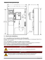
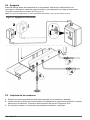
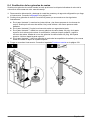
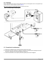
3.2 Mechanical installation
C A U T I O N
Personal injury hazard. Instruments or components are heavy. Use assistance to install
or move.
C A U T I O N
Personal injury hazard. Lift the instrument by the stainless steel backplate. Do not lift the
instrument by the mounted components. The mounted components can break and
cause damage to the instrument and personal injury.
C A U T I O N
Personal injury hazard. Sharp edges can cause cut wounds. Wear personal protective
equipment to prevent injury.
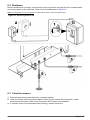
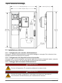
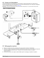
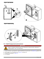
Install the instrument on a wall. Refer to Figure 5. To install on drywall, attach the instrument to the
wood studs with
3
/
8
-inch (M10) hardware.
Use sufficient supports to keep vibrations, gravity and thermal loads on the connections to a
minimum.
English
11

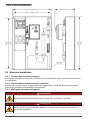
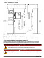
Figure 5 Mounting dimensions
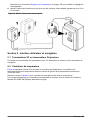
3.3 Electrical installation
3.3.1 Connect the controller to power
Connect the controller to line power by hard-wiring in conduit. Refer to the controller documentation
for instructions.
3.3.2 Connect external devices to the controller
Connect the controller relays, analog outputs and digital inputs to external devices as necessary.
Refer to the controller documentation for instructions.
3.3.3 Wiring the instrument for power
D A N G E R
Electrocution hazard. Protective Earth Ground (PE) connection is required.
D A N G E R
Electrical shock and fire hazards. Make sure to identify the local disconnect clearly for
the conduit installation.
12 English

W A R N I N G
Potential Electrocution Hazard. If this equipment is used outdoors or in potentially wet
locations, a Ground Fault Interrupt device must be used for connecting the equipment to
its mains power source.
W A R N I N G
Electrical shock and fire hazards. Make sure that the user-supplied power cord and non‐
locking plug meet the applicable country code requirements.
Connect power to the controller(s) with electrical conductors and conduit. Do not use a power cord.
Make sure that a circuit breaker with sufficient current capacity is installed in the power line. The
circuit breaker size is based on the wire gauge used for installation. Install the device in a location
and position that gives easy access to the disconnect device and its operation.
For installation with conduit:
• Install a local disconnect for the instrument within 3 m (10 ft) of the instrument. Put a label on the
disconnect that identifies it as the main disconnect device for the instrument.
• Make sure that the electrical conductors for the power and safety ground service drops for the
instrument are a minimum of 3.31 mm
2
(12 AWG) (for 110 V) and a minimum of 2.08 mm
2
(14 AWG) (for 220 V) and the wire insulation is rated for 300 VAC or higher and 60 °C (140 °F)
minimum.
• Connect equipment in accordance with local, state or national electrical codes.
• Connect the conduit through a conduit hub that holds the conduit securely and seals the enclosure
when tightened to keep the NEMA 4x rating of the instrument.
• If metal conduit is used, make sure that the conduit hub is tightened so that the conduit hub
connects the metal conduit to safely ground.
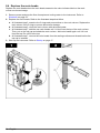
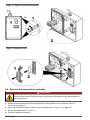
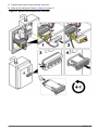
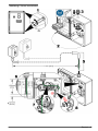
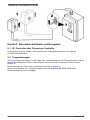
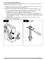
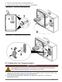
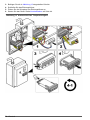
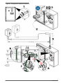
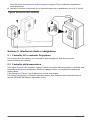
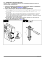
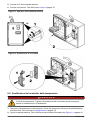
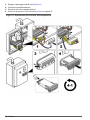
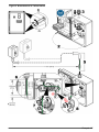
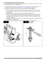
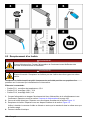
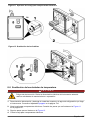
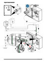
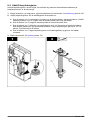
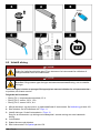
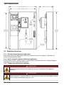
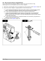
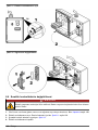
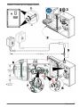
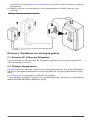
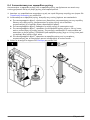
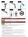
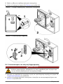
3.3.4 Connect the instrument to power
Connect power to the electrical enclosure. Refer to Table 1 and the illustrated steps in Figure 6.
After the wires are connected, tighten the conduit fitting, close the electrical enclosure and tighten the
screws.
Notes:
• At illustrated step 3, cut an opening in the top or bottom of the electrical enclosure for the conduit.
• At illustrated step 4, install a conduit fitting in the opening to keep the enclosure rating of the
instrument (NEMA 4x).
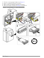
• At illustrated step 6, make sure that the free length of wire conductors for the electrical enclosure
is a minimum of 150 mm (6 in.).
For electrical safety, the protective earth ground wire (G) must be at least 0.5 inches longer than the
Line (L) and Neutral (N) wires. Make sure that each wire goes through the applicable cable clamp as
shown in Figure 6.
English
13

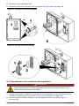
Figure 6 Connect power
14 English

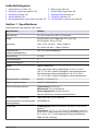
Table 1 Wiring information—AC power
Terminal Description Color—North America Color—EU
L Hot or phase (L) Black Brown
N Neutral (N) White Blue
G Protective earth ground (G) Green Yellow with green stripe
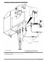
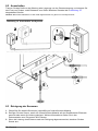
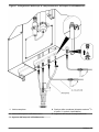
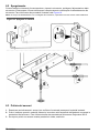
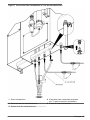
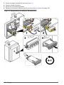
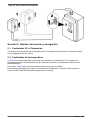
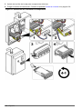
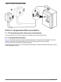
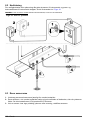
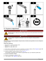
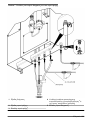
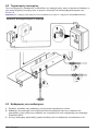
3.4 Plumbing
3.4.1 Connect the sample water and cooling water
Note: Do not install metric equivalent tubing, pipes or fittings on the instrument. Leaks can occur.
Items to collect:
• Shutoff valve (3x)
• ¼-inch tubing OD
•
3
/
8
-inch tubing ID
• Tubing clamp
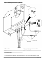
1. Use ¼-inch tubing and three shutoff valves to connect the sample water and cooling water. Refer
to Figure 7.
2. Use the supplied
3
/
8
-inch ID tubing and tubing clamp to connect the condensate drain to an open
drain. Refer to Figure 7.
Notes:
• Do not connect cooling water to instruments with the regenerative cooling option. Instruments
with the regenerative cooling option do not have a cooling water inlet or outlet.
• Refer to Specifications on page 3 for the cooling water and sample water specifications.
• Make sure to use a back pressure regulator or a head cup to control the sample water
pressure and keep a constant sample flow rate.
• Keep the operating temperature of the sample flow as constant as possible for best
performance.
• For the best results, use a temperature-controlled cooling water source that keeps the cooling
water at 25 °C (77 °F).
• Make the drain lines as short as possible.
• Make sure that the drain lines have a constant slope down.
• Make sure that the drain lines do not have sharp bends and are not pinched.
• Make sure that the drain lines are open to air and are at zero back pressure.
English
15

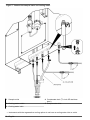
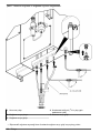
Figure 7 Connect the sample water and cooling water
1 Sample outlet 4 Condensate drain (
3
/
8
-inch OD stainless
steel)
2 Cooling water outlet
4
5 Sample water inlet
3 Cooling water inlet
4
4
Instruments with the regenerative cooling option do not have a cooling water inlet or outlet.
16 English

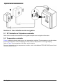
Section 4 Startup
W A R N I N G
Burn hazard. The heater surface and surrounding area gets hot. Do not touch.
W A R N I N G
Burn hazard. Obey safe handling protocols during contact with hot liquids.
1. Examine the resin beads in the resin column. Refer to Figure 1 on page 7.
2. Replace the resin beads when the resin beads nearest to the color indicator label on the resin
column are brown/orange. Refer to Replace the resin beads on page 24.
Note: The color change of the resin beads starts at the top and continues to the bottom of the resin column.
New resin beads are dark purple.
3. Set the flow rate of the cooling water flow as follows, if applicable:
a. Use the shutoff valve at the cooling water outlet to adjust the flow rate of the cooling water to
approximately 0.8 L/min (0.2 gal/min).
b. Make sure that there are no leaks at the cooling water fittings.
4. Set the flow rate of the sample water as follows:
a. Open the shutoff valve for the sample water inlet.
b. Turn the sample flow valve to set the flow rate of the sample water to between 100 to
150 mL/min. Refer to Figure 1 on page 7.
c. Make sure that there are no leaks at the sample water fittings.
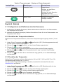
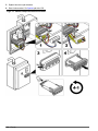
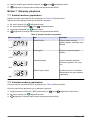
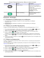
5. Set the instrument to on. Refer to the illustrated steps in Figure 8.
• The power indicator light comes on.
Note: The power indicator light starts and stops with the heater.
• The heater increases the sample temperature to the boiling point of water.
6. Wait for the temperature that shows on the left display of the temperature controller to increase to
approximately 106 °C (223 °F). Refer to Figure 9 on page 19.
Note: The temperature controller may not get to 106 °C (223 °F), based on local air pressure and temperature.
7. Examine the condensate water that comes out the condensate drain. When the temperature and
sample flow rate are set correctly, a small flow of condensed water continually comes out from
the condensate drain.
• If no condensate water comes out the condensate drain, decrease the sample flow rate (range:
100 to 150 mL/min) or increase the temperature setpoint (range: 106 to 108 °C, 223 to 226 °F).
• If drops of hot boiling water come out the condensate drain, increase the sample flow rate
(range: 100 to 150 mL/min) or decrease the temperature setpoint (range: 106 to 108 °C, 223 to
226 °F).
Refer to Set the temperature on page 20 to change the temperature setting.
8. Let the instrument operate until the reading(s) is stable (approximately 10 to 15 minutes).
English
17

Figure 8 Set the instrument to on
Section 5 User interface and navigation
5.1 SC Controller or Polymetron controller
Refer to the controller documentation for keypad description and navigation information.
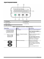
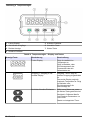
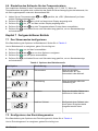
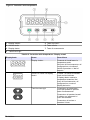
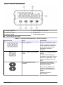
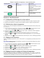
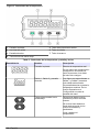
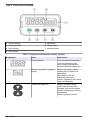
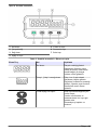
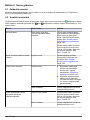
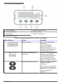
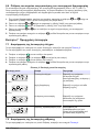
5.2 Temperature controller
Figure 9 shows the display and keys on the temperature controller. The temperature controller shows
the actual temperature on the left display and the maximum temperature on the right display.
Refer to Table 2 for descriptions of the keys and the display.
For more information on the temperature controller, refer to the Watlow EZ-ZONE PM Express User's
Guide (available online).
18
English

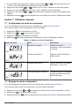
Figure 9 Temperature controller
1 Left display 5 Up arrow key
2 Output activity 6 Infinity key
3 Right display 7 Advance key
4 Down arrow key
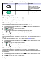
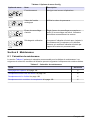
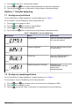
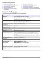
Table 2 Temperature controller—Display and keys
Display/Key Name Description
Left display Shows the actual temperature.
In the Operations or Setup
menu, shows the process value
or setpoint data.
1 2
Output 1, Output 2 and right
display
Output 1 and 2 shows which
output is set to on.
The right display shows the
maximum temperature. In the
Operations or Setup menu,
shows the menu display.
Up/Down arrow keys Selects new data when
Advance key is pushed.
Moves forward or backward
through software menus and
parameters.
Starts and stops the timer.
English 19

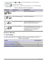
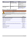
Table 2 Temperature controller—Display and keys (continued)
Display/Key Name Description
Infinity key Stops alarms.
Push to go back one level.
Push and hold for two seconds
to go back to the Operations
menu.
Advance key Moves forward through
parameter prompts.
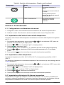
Section 6 Operation
6.1 Configure and calibrate the sensor(s)
1. Configure the sensor(s). Refer to the Polymetron 8315 sensor documentation.
2. Calibrate the sensor(s). Refer to the Polymetron 8315 sensor documentation.
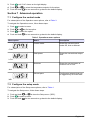
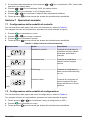
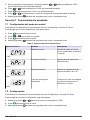
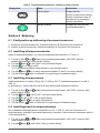
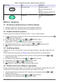
6.2 Set the temperature units
Set the temperature units that show on the temperature controller to °F or °C.
1. At the temperature controller, push and hold and until "SEt" (setup parameters menu)
shows on the right display.
2. Push or until "gLbL" shows on the left display.
3. Push to select "gLbL".
"C_F" (temperature unit of measure parameters) shows on the right display.
4. Push or to select the temperature unit (C or F) on the left display.
5. Push and hold for two seconds to go back to the default display.
6.3 Set the temperature
Set the temperature to between 106 and 108 °C (223 and 226 °F). The default temperature is 108 °C
(226 °F).
To identify the correct temperature setting, refer to the last steps in Startup on page 17.
1. At the temperature controller, push and hold and until "oPEr" (operations menu) shows
on the right display.
2. Push or until "LooP" shows on the left display.
3. Push until "C.SP" shows on the right display.
4. Push or to select the temperature.
5. Push and hold for two seconds to go back to the default display.
6.4 Set the temperature alarm setpoint
The recommended temperature alarm setpoint is 110 °C (230 °F). When a temperature alarm
occurs, the instrument removes power to the heater until the heater temperature decreases to below
the alarm setpoint.
1. At the temperature controller, push and hold and until "oPEr" (operations menu) shows
on the right display.
2. Push or until "ALM" shows on the left display.
20
English
Sayfa yükleniyor...
Sayfa yükleniyor...
Sayfa yükleniyor...
Sayfa yükleniyor...
Sayfa yükleniyor...
Sayfa yükleniyor...
Sayfa yükleniyor...
Sayfa yükleniyor...
Sayfa yükleniyor...
Sayfa yükleniyor...
Sayfa yükleniyor...
Sayfa yükleniyor...
Sayfa yükleniyor...
Sayfa yükleniyor...
Sayfa yükleniyor...
Sayfa yükleniyor...
Sayfa yükleniyor...
Sayfa yükleniyor...
Sayfa yükleniyor...
Sayfa yükleniyor...
Sayfa yükleniyor...
Sayfa yükleniyor...
Sayfa yükleniyor...
Sayfa yükleniyor...
Sayfa yükleniyor...
Sayfa yükleniyor...
Sayfa yükleniyor...
Sayfa yükleniyor...
Sayfa yükleniyor...
Sayfa yükleniyor...
Sayfa yükleniyor...
Sayfa yükleniyor...
Sayfa yükleniyor...
Sayfa yükleniyor...
Sayfa yükleniyor...
Sayfa yükleniyor...
Sayfa yükleniyor...
Sayfa yükleniyor...
Sayfa yükleniyor...
Sayfa yükleniyor...
Sayfa yükleniyor...
Sayfa yükleniyor...
Sayfa yükleniyor...
Sayfa yükleniyor...
Sayfa yükleniyor...
Sayfa yükleniyor...
Sayfa yükleniyor...
Sayfa yükleniyor...
Sayfa yükleniyor...
Sayfa yükleniyor...
Sayfa yükleniyor...
Sayfa yükleniyor...
Sayfa yükleniyor...
Sayfa yükleniyor...
Sayfa yükleniyor...
Sayfa yükleniyor...
Sayfa yükleniyor...
Sayfa yükleniyor...
Sayfa yükleniyor...
Sayfa yükleniyor...
Sayfa yükleniyor...
Sayfa yükleniyor...
Sayfa yükleniyor...
Sayfa yükleniyor...
Sayfa yükleniyor...
Sayfa yükleniyor...
Sayfa yükleniyor...
Sayfa yükleniyor...
Sayfa yükleniyor...
Sayfa yükleniyor...
Sayfa yükleniyor...
Sayfa yükleniyor...
Sayfa yükleniyor...
Sayfa yükleniyor...
Sayfa yükleniyor...
Sayfa yükleniyor...
Sayfa yükleniyor...
Sayfa yükleniyor...
Sayfa yükleniyor...
Sayfa yükleniyor...
Sayfa yükleniyor...
Sayfa yükleniyor...
Sayfa yükleniyor...
Sayfa yükleniyor...
Sayfa yükleniyor...
Sayfa yükleniyor...
Sayfa yükleniyor...
Sayfa yükleniyor...
Sayfa yükleniyor...
Sayfa yükleniyor...
Sayfa yükleniyor...
Sayfa yükleniyor...
Sayfa yükleniyor...
Sayfa yükleniyor...
Sayfa yükleniyor...
Sayfa yükleniyor...
Sayfa yükleniyor...
Sayfa yükleniyor...
Sayfa yükleniyor...
Sayfa yükleniyor...
Sayfa yükleniyor...
Sayfa yükleniyor...
Sayfa yükleniyor...
Sayfa yükleniyor...
Sayfa yükleniyor...
Sayfa yükleniyor...
Sayfa yükleniyor...
Sayfa yükleniyor...
Sayfa yükleniyor...
Sayfa yükleniyor...
Sayfa yükleniyor...
Sayfa yükleniyor...
Sayfa yükleniyor...
Sayfa yükleniyor...
Sayfa yükleniyor...
Sayfa yükleniyor...
Sayfa yükleniyor...
Sayfa yükleniyor...
Sayfa yükleniyor...
Sayfa yükleniyor...
Sayfa yükleniyor...
Sayfa yükleniyor...
Sayfa yükleniyor...
Sayfa yükleniyor...
Sayfa yükleniyor...
Sayfa yükleniyor...
Sayfa yükleniyor...
Sayfa yükleniyor...
Sayfa yükleniyor...
Sayfa yükleniyor...
Sayfa yükleniyor...
Sayfa yükleniyor...
Sayfa yükleniyor...
Sayfa yükleniyor...
Sayfa yükleniyor...
Sayfa yükleniyor...
Sayfa yükleniyor...
Sayfa yükleniyor...
Sayfa yükleniyor...
Sayfa yükleniyor...
Sayfa yükleniyor...
Sayfa yükleniyor...
Sayfa yükleniyor...
Sayfa yükleniyor...
Sayfa yükleniyor...
Sayfa yükleniyor...
Sayfa yükleniyor...
Sayfa yükleniyor...
Sayfa yükleniyor...
Sayfa yükleniyor...
Sayfa yükleniyor...
Sayfa yükleniyor...
Sayfa yükleniyor...
Sayfa yükleniyor...
Sayfa yükleniyor...
Sayfa yükleniyor...
Sayfa yükleniyor...
Sayfa yükleniyor...
Sayfa yükleniyor...
Sayfa yükleniyor...
Sayfa yükleniyor...
Sayfa yükleniyor...
Sayfa yükleniyor...
Sayfa yükleniyor...
Sayfa yükleniyor...
Sayfa yükleniyor...
Sayfa yükleniyor...
Sayfa yükleniyor...
Sayfa yükleniyor...
Sayfa yükleniyor...
Sayfa yükleniyor...
Sayfa yükleniyor...
Sayfa yükleniyor...
Sayfa yükleniyor...
Sayfa yükleniyor...
Sayfa yükleniyor...
Sayfa yükleniyor...
Sayfa yükleniyor...
Sayfa yükleniyor...
Sayfa yükleniyor...
Sayfa yükleniyor...
Sayfa yükleniyor...
Sayfa yükleniyor...
Sayfa yükleniyor...
Sayfa yükleniyor...
Sayfa yükleniyor...
Sayfa yükleniyor...
Sayfa yükleniyor...
Sayfa yükleniyor...
Sayfa yükleniyor...
Sayfa yükleniyor...
Sayfa yükleniyor...
Sayfa yükleniyor...
Sayfa yükleniyor...
Sayfa yükleniyor...
Sayfa yükleniyor...
Sayfa yükleniyor...
Sayfa yükleniyor...
Sayfa yükleniyor...
Sayfa yükleniyor...
Sayfa yükleniyor...
Sayfa yükleniyor...
Sayfa yükleniyor...
Sayfa yükleniyor...
Sayfa yükleniyor...
Sayfa yükleniyor...
-
 1
1
-
 2
2
-
 3
3
-
 4
4
-
 5
5
-
 6
6
-
 7
7
-
 8
8
-
 9
9
-
 10
10
-
 11
11
-
 12
12
-
 13
13
-
 14
14
-
 15
15
-
 16
16
-
 17
17
-
 18
18
-
 19
19
-
 20
20
-
 21
21
-
 22
22
-
 23
23
-
 24
24
-
 25
25
-
 26
26
-
 27
27
-
 28
28
-
 29
29
-
 30
30
-
 31
31
-
 32
32
-
 33
33
-
 34
34
-
 35
35
-
 36
36
-
 37
37
-
 38
38
-
 39
39
-
 40
40
-
 41
41
-
 42
42
-
 43
43
-
 44
44
-
 45
45
-
 46
46
-
 47
47
-
 48
48
-
 49
49
-
 50
50
-
 51
51
-
 52
52
-
 53
53
-
 54
54
-
 55
55
-
 56
56
-
 57
57
-
 58
58
-
 59
59
-
 60
60
-
 61
61
-
 62
62
-
 63
63
-
 64
64
-
 65
65
-
 66
66
-
 67
67
-
 68
68
-
 69
69
-
 70
70
-
 71
71
-
 72
72
-
 73
73
-
 74
74
-
 75
75
-
 76
76
-
 77
77
-
 78
78
-
 79
79
-
 80
80
-
 81
81
-
 82
82
-
 83
83
-
 84
84
-
 85
85
-
 86
86
-
 87
87
-
 88
88
-
 89
89
-
 90
90
-
 91
91
-
 92
92
-
 93
93
-
 94
94
-
 95
95
-
 96
96
-
 97
97
-
 98
98
-
 99
99
-
 100
100
-
 101
101
-
 102
102
-
 103
103
-
 104
104
-
 105
105
-
 106
106
-
 107
107
-
 108
108
-
 109
109
-
 110
110
-
 111
111
-
 112
112
-
 113
113
-
 114
114
-
 115
115
-
 116
116
-
 117
117
-
 118
118
-
 119
119
-
 120
120
-
 121
121
-
 122
122
-
 123
123
-
 124
124
-
 125
125
-
 126
126
-
 127
127
-
 128
128
-
 129
129
-
 130
130
-
 131
131
-
 132
132
-
 133
133
-
 134
134
-
 135
135
-
 136
136
-
 137
137
-
 138
138
-
 139
139
-
 140
140
-
 141
141
-
 142
142
-
 143
143
-
 144
144
-
 145
145
-
 146
146
-
 147
147
-
 148
148
-
 149
149
-
 150
150
-
 151
151
-
 152
152
-
 153
153
-
 154
154
-
 155
155
-
 156
156
-
 157
157
-
 158
158
-
 159
159
-
 160
160
-
 161
161
-
 162
162
-
 163
163
-
 164
164
-
 165
165
-
 166
166
-
 167
167
-
 168
168
-
 169
169
-
 170
170
-
 171
171
-
 172
172
-
 173
173
-
 174
174
-
 175
175
-
 176
176
-
 177
177
-
 178
178
-
 179
179
-
 180
180
-
 181
181
-
 182
182
-
 183
183
-
 184
184
-
 185
185
-
 186
186
-
 187
187
-
 188
188
-
 189
189
-
 190
190
-
 191
191
-
 192
192
-
 193
193
-
 194
194
-
 195
195
-
 196
196
-
 197
197
-
 198
198
-
 199
199
-
 200
200
-
 201
201
-
 202
202
-
 203
203
-
 204
204
-
 205
205
-
 206
206
-
 207
207
-
 208
208
-
 209
209
-
 210
210
-
 211
211
-
 212
212
-
 213
213
-
 214
214
-
 215
215
-
 216
216
-
 217
217
-
 218
218
-
 219
219
-
 220
220
-
 221
221
-
 222
222
-
 223
223
-
 224
224
-
 225
225
-
 226
226


diğer dillerde
- español: Hach 9525sc Manual de usuario
- français: Hach 9525sc Manuel utilisateur
- italiano: Hach 9525sc Manuale utente
- Deutsch: Hach 9525sc Benutzerhandbuch
- English: Hach 9525sc User manual
- dansk: Hach 9525sc Brugermanual
İlgili makaleler
-
 Hach 9525sc Kullanım kılavuzu
-
 Hach Polymetron 9526 Basic User Manual
-
 Hach Polymetron 9523sc pH Basic User Manual
-
Hach CL17sc Kullanım kılavuzu
-
Hach SC4200c User Instructions
-
 Hach NA5600 sc Na+ Maintenance And Troubleshooting Manual
-
 Hach 9586sc Basic User Manual
-
 Hach CLT10sc Kullanım kılavuzu
-
 Hach AS950 Basic Operations
-
 Hach AS950 Basic Installation And Maintenance


