
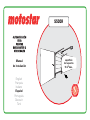
S500R
W
A
R
R
A
N
T
Y
•
G
A
R
A
N
T
I
E
•
G
A
R
A
N
Z
I
A
•
G
A
R
A
N
T
I
A
•
G
A
R
A
N
T
I
E
•
G
A
R
A
N
T
I
E
•
Y
E
A
R
S
•
A
N
S
•
A
N
N
I
•
A
Ñ
O
S
•
A
N
O
•
J
A
H
R
E
•
3
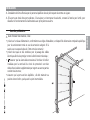
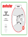
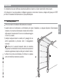
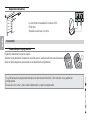
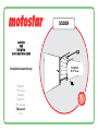
Installation
manual
OPERATOR
OPERATOR
FOR
FOR
OVERHEAD GARAGE
OVERHEAD GARAGE
OR SECTIONAL DOORS
OR SECTIONAL DOORS
surface area
of the door
9 m2 max
English
Français
Italiano
Español
Português
Deutsch
Türk

2
-
FG00705M07
-
1
- 09/2017
ENGLISH
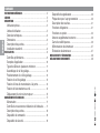
SUMMARY
GENERAL PRECAUTIONS .. .............................................................3
KEY ...............................................................................................5
DESCRIPTION . ..............................................................................5
Intended use ............................................................5
Operating limits .......................................................5
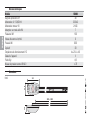
Technical data ... .......................................................6
Dimensions .. ............................................................ 6
Description of parts ... ..............................................7
Standard installation .. ..............................................8
INSTALLATION ..............................................................................9
Preliminary checks . ..................................................9
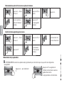
Applicative examples .. ............................................ 10
Cable type and minimum thicknesses ... .................... 11
Assembling the traction guide .... .............................. 12
Positioning the traction guide .................................. 12
Fastening the traction guide . .................................. 13
Fitting the transmission arm to the door . ................. 14
Fitting the operator to the guide .............................. 14
Moving the micro switch . ....................................... 15
ELECTRICAL CONNECTIONS .... .....................................................17
Input voltage .......................................................... 17
Movement control and obstacle detection ......... ........ 17
Description of parts ... ............................................ 18
Command and control devices .... .............................. 19
Safety devices .. ..................................................... 19
Signaling devices .... ................................................20
Preparing for programming ... ..................................20
Description of keys ................................................21
Obligatory functions ... ............................................ 21
Optional functions .. ................................................23
Additional external antenna ... ..................................26
Radio frequency card . ............................................26
Memorizing the transmitters ..................................27
Deleting transmitters . ............................................27
DISMANTLING AND DISPOSAL .....................................................28
DECLARATION OF CONFORMITY ....................................................28

3
-
FG00705M07
-
1
- 09/2017
ENGLISH
CAUTION: Important safety instructions.
Follow all instructions. Improper installation may lead to serious
bodily injuries. Before continuing, also read the precautions in the
operating and maintenance manual.
GENERAL PRECAUTIONS
This product must only be used for its specifi cally intended
purpose. Any other use is dangerous. LABEL HABITAT SAS
is not liable for any damage caused by improper, wrongful or
unreasonable use of this product. • This manual's product
is defi ned by machinery directive 2006/42/CEas "partly-
completed machinery". Partly-completed machinery is a set
that almost constitutes a machine, but which, alone, cannot
ensure a clearly defi ned application. Partly-completed
machinery is only destined to be incorporated or assembled
to other machinery or other partly-completed machinery or
apparatuses to build machinery that is regulated by Directive
2006/42/CE. The fi nal installation must be compliant with
European directive 2006/42/CE and European reference
standards: EN 13241-1, EN 12453, EN 12445 and
EN 12635. Given these considerations, all procedures
stated in this manual must be exclusively performed
by expert, qualifi ed staff.• The operator cannot be
used with gates fi tted with pedestrian doors, unless
its operation can be activated only when the pedestrian
door is in safety position • Make sure that people are not
entrapped between the gate's moving and fi xed parts due
to the gate's movement • Before installing the operator,
check that the gate is in proper mechanical conditions, that
it is properly balanced and that it properly closes: if any of
these conditions are not met, do not continue before having
met all safety requirements • Make sure that opening and
closing limiters are fi tted • Make sure the operator is
installed onto a sturdy surface that is protected from any
impacting shocks • Make sure that mechanical stops are
already installed • If the operator is installed lower than
2.5 from the ground or from any other access level, fi t any
protections and signs to prevent hazardous situations •
Do not fi t the operator upside down or onto elements that
could yield to its weight If necessary, add reinforcements
to the fastening points • Do not install door or gate leaves
on tilted surfaces • Check that no lawn watering devices
spray the operator with water from the bottom up •
Suitably section off and demarcate the entire installation
site to prevent unauthorized persons from entering the
area, especially minors and children • Fit cautionary signs,

4
-
FG00705M07
-
1
- 09/2017
ENGLISH
such as the gate plate, wherever needed and in plain sight.
• Use proper protections to prevent mechanical hazards
when people are loitering around the machinery's range
of action, for example avoid crushing of fi ngers between
the drive shaft and the mechanical stops, avoid crushing
when the gate is opening • The electrical cables must run
through the cable glands and not touch any parts that may
overheat, such as the motor, transformer, and so on • All
command and control devices must be installed at least
1.85 m from the perimeter of the gate's range of action
or where they cannot be reached through the gate from
the outside • All switches in maintained action mode must
be positioned so that the moving gates leaves, the transit
areas and vehicle thru-ways are completely visible, and yet
the switches must be also away from any moving parts •
Unless a key switch is used, all control devices must be
fi tted at a height of at least 1.5 mand wherethey are not
accessible to the public • Before handing over to users,
check that the system is compliant with the 2006/42/
CEuniformed Machinery Directive.Make sure that the
operator has been properly adjusted and that the safety
and protection devices, and the manual release, are working
properly • Affi x a permanent tag, that describes how to
use the manual release mechanism, close to the mechanism
• Make sure to hand over to the end user, all operating
manuals for the products that make up the fi nal machinery
• Set up a suitable dual pole cut off device along the power
supply that is compliant with the installation rules. It should
completely cut off the powersupply according to category III
surcharge conditions • The gearmotor must be exclusively
powered by very low safety voltage, which corresponds to
what is stated in the markings on the motor itself, and by
using the control panel supplied in the KIT.

5
-
FG00705M07
-
1
- 09/2017
ENGLISH
KEY
This symbol shows which parts to read carefully.
This symbol shows which parts describe safety issues
This symbol shows which parts to tell users about.
THE MEASUREMENTS, UNLESS OTHERWISE STATED, ARE IN MILLIMETERS. THE CONTENTS OF THIS MANUAL MAY CHANGE, AT ANY TIME, AND WITHOUT NOTICE.
DESCRIPTION
Complete system with control board, device for controlling the movement and the obstruction detection for overhead garage and
sectional doors with maximum surface area of 9 m2.
Intended use
This operator is designed to power overhead garage and sectional doors used in homes and apartment buildings.
Any installation and/or use other than that specifi ed in this manual is forbidden.
Operating limits
Model S500R
Door surface area (m2) 9
Maximum height of counterbalanced overhead doors (m) 2.4
Maximum height of spring-balanced overhead doors (m) 3.25
Maximum height of door (m) 3.20

6
-
FG00705M07
-
1
- 09/2017
ENGLISH
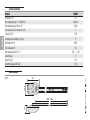
Dimensions
(mm)
Technical data
Model S500R
Protection rating (IP) 40
Power supply (V - 50/60 Hz) 230 AC
Motor power supply (V) 24 DC
Draw when in stand-by (W) 7
Power (W) 100
Opening speed (m/min) 6
Thrust (N) 600
Cycles/hr 30
Operating temperature (°C) -20 ÷ +40
Apparatus class II
Weight (Kg) 4.9
Acoustic pressure level (dB (A)) ≤70
210115
365
3020 ÷ 4020

7
-
FG00705M07
-
1
- 09/2017
ENGLISH
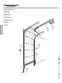
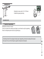
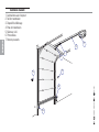
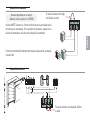
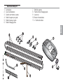
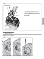
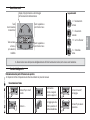
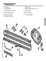
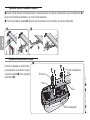
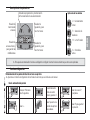
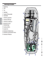
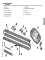
Description of parts
1. Operator
2. Power supply cable
3. Chain operated slide rail
4. Rail-supporting braces
5. Head braces for rails
6. Door fastening brace
7. Supporting braces
8. Perforated tabs for fastening the rail
9. Curved lever
10. Transmission arm
Release cord

8
-
FG00705M07
-
1
- 09/2017
RX
TX
6
1
57
6
2
3
4
ENGLISH
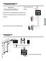
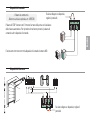
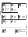
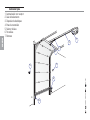
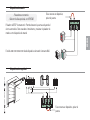
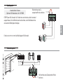
Standard installation
1. Operator with receiver
2. Slide guide
3. Release device
4. Transmission arm
5. Key-switch selector
6. Photocells
7. Keypad

9
-
FG00705M07
-
1
- 09/2017
ENGLISH
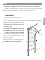
Preliminary checks
Before beginning the installation, do the following:
• make sure you have set up a suitable dual pole cut off device along the power supply that is compliant with the installation rules.
It should completely cut off the power supply according to category
III surcharge conditions (that is, with minimum contact openings of
3 mm);
• Setup suitable tubes and conduits for the electric cables to pass
through, making sure they are protected from any mechanical
damage;
• make sure that any connections inside the container (ones that
ensure continuity to the protection circuit) are fitted with additional
insulation with respect to those of other electrical parts inside:
• make sure that the door is properly balanced. When stopped at any
point, it must maintain its position.
INSTALLATION
Only skilled, qualifi ed staff must install this product.
If the door is fi tted with a pedestrian door, you must also fi t a safety switch at the entrance, to stop the operator from working
when the pedestrian door is open.

10
-
FG00705M07
-
1
- 09/2017
(
H - 100 mm
H
H - 100 mm
H
((
ENGLISH
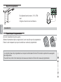
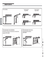
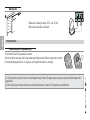
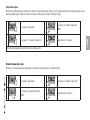
Applicative examples
* single rail
sectional door
* double rain
sectional door
SECTIONAL DOOR
COUNTERBALANCED OVERHEAD,
protruding and partially-retracting door (needs the 801XC-0060
adapter arm)
SPRING-BALANCED OVERHEAD DOOR,
fully retracting and protruding

11
-
FG00705M07
-
1
- 09/2017
ENGLISH
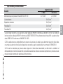
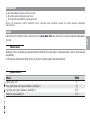
Cable type and minimum thicknesses
Connection cable length
< 20 m 20 < 30 m
Control board power supply 230 V AC (1P+N) 2 x 1.5 mm22 x 2.5 mm2
Flashing light 2 x 0.5 mm2
Command and control devices 2 x 0.5 mm2
TX Photocells 2 x 0.5 mm2
RX photocells 4 x 0.5 mm2
When operating at 230 V and outdoors, use H05RN-F-type cables that are 60245 IEC 57 (IEC) compliant; whereas indoors, use
H05VV-F-type cables that are 60227 IEC 53 (IEC) compliant. For power supplies up to 48 V, you can use FROR 20-22 II-type cables
that comply with EN 50267-2-1 (CEI).
If cable lengths differ from those specified in the table, establish the cable sections depending on the actual power draw of the
connected devices and according to the provisions of regulation CEI EN 60204-1.
For multiple, sequential loads along the same line, the dimensions on the table need to be recalculated according to the actual power
draw and distances. For connecting products that are not contemplated in this manual, see the literature accompanying said products

12
-
FG00705M07
-
1
- 09/2017
M6x80 M6
10 ÷ 20
801XC-0060
20 ÷ 30
max 330
ENGLISH
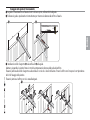
The following illustrations are just examples, in that the space available for fitting the operator and accessories varies depending on the
overall dimensions. It is up to the installer to find the most suitable solution.
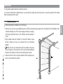
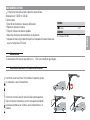
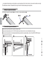
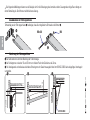
Assembling the traction guide
Fitting the brace to the transmission guide use the supplied nut and bolt .
Positioning the traction guide
for sectional doors exceeding the overall dimensions of the spring-pole brace.
for overhead doors between 10 and 20 mm from the apex point of the leaf's slide arc.
for partially retracting protruding counter-balanced overhead doors, use the 801XC-0060 arm (see the enclosed technical literature).

13
-
FG00705M07
-
1
- 09/2017
?
ENGLISH
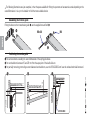
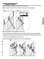
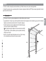
Fastening the traction guide
Fasten the traction guide to the center of the doorway, using suitable screws.
Raise the guide and position in horizontally to measure the distance to the ceiling, then fasten it.
Instal the support braces and the U-shaped brace onto the guide.
Bend the perforated flat tabs so they fit snugly and so as to compensate for the distance between the guide and ceiling.
Fasten the flat tabs to the support braces and to the U-shaped brace using the supplied screws and washers. Drill the ceiling so the
holes match those on the flat tabs.
Fasten the flat tabs to the ceiling using suitable dowels and screws.

14
-
FG00705M07
-
1
- 09/2017
ENGLISH
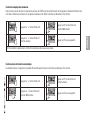
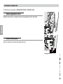
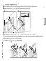
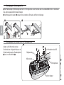
Guide
Drive shaft with adapter
Self-drilling 6 x 15 screw
U-shaped brace
Micro
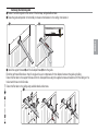
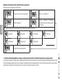
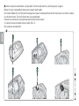
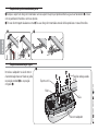
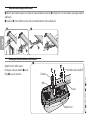
Fitting the operator to the guide
Fit the adapter to the drive shaft.
The operator can be fitted onto the guide:
either in standard position or at a right
angle .
Fit the transmission arm brace to the upper beam of the door, perpendicularly to the traction guide and fasten it using the supplied
screws or other suitable fasteners.
If mounting the curved lever fit it to the transmission arm by using the supplied nuts and bolts
Fitting the transmission arm to the door

15
-
FG00705M07
-
1
- 09/2017
ENGLISH
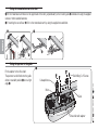
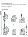
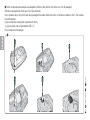
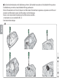
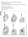
Moving the micro switch
Disconnect the cables of the micro switch and remove the latter.
If the operator is to be fitted at a right angle, before
installing it, set the micro-switch (see the corresponding
paragraph).
Self-drilling 6 x 15 screw
U-shaped brace
Guide
Drive shaft with adapter
Micro

16
-
FG00705M07
-
1
- 09/2017
ENGLISH
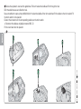
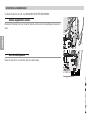
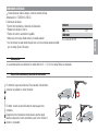
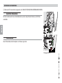
Remove the operator's cover and the gable brace. Pull out the electrical cable and fit it through the hole.
Refit the cable brace so as to block the hole.
Use a screwdriver to open up the predrilled hole for the electrical cables of the micro switch and fir the cables to the micro switch. Fit
the micro switch to the operator.
Connect the connectors to the corresponding positions on the micro switch.
Reconnect the cables as originally connected (NO - C).
Fit the cover back onto the operator.

17
-
FG00705M07
-
1
- 09/2017
ENGLISH
When CLOSING: inverts the direction of travel until opening is
complete.
After three consecutive inversions, the door stays open and exclu-
des the automatic closing: to close, either use the transmitter or
button.
When OPENING; the door stops. To resume movement, either press
a button or use the transmitter.
Movement control and obstacle detection
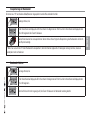
ELECTRICAL CONNECTIONS
Before powering up the board, cut off the mains power supply.
Power supply (V - 50/60 Hz): 230 AC
Board functions:
• Movement control and obstacle detection
• Reopening during closing
• Adjustable automatic reclosing time
• Open-stop-close-stop from transmitter and/or from button
• Courtesy light (at each opening command, the courtesy light stays on for three
minutes))
FUSES
- Line 5 A F
LIGHTS
LED courtesy (W) ≤ 1
Input voltage
The operator is supplied with an electrical cable (L = 1.2 m) with an already connected Shuko plug.

18
-
FG00705M07
-
1
- 09/2017
AF
4
2
8
91011
3
1
13
14 16
7
15
6
5
12
ENGLISH
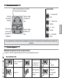
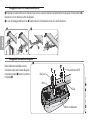
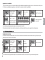
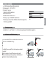
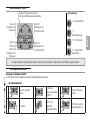
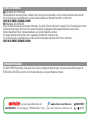
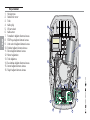
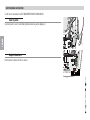
Description of parts
1. Line fuse
2. Gearmotor
3. Transformer
4. Cables input
5. AF card connector
6. Antenna cable
7. Photocells connection terminal board
8. STOP button connection terminal board
9. Limit switch connection terminal board
10. Encoder connection terminals
11. Display connection terminal board
12. Motor connections
13. Transformer connections
14. Courtesy light connection terminal board
15. Antenna connection terminals
16. Flashing light connection terminal boards

19
-
FG00705M07
-
1
- 09/2017
RX
TX
ENGLISH
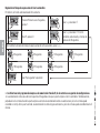
Command and control devices
Function OPEN-STOP-CLOSE-STOP from a control device (NO contact).
STOP button (NC contact). FOR stopping the door while excluding the automa-
tic closing. To resume movement either press the control button or any other
control device.
If a device is connected, remove the bridge
If a device is connected, remove
the bridge
Safety devices
- Marketed buttons.
- Optional key-switch selector, KEYSTAR item.

20
-
FG00705M07
-
1
- 09/2017
ENGLISH
Flashing light (contact rated for: 24 V - 25 W max).
It flashes during opening and closing.
Signaling devices
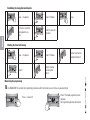
Preparing for programming
Manually hook up the door to the skid.
Power up the operator. After emitting a sound signal, the control board is ready for programming.
Remove the transparent panel to access the programming keys.
Memorizing (function 5) must always be the last phase of programming, otherwise the settings will not be saved.
In the case of errors, cut off and the power up again the mains power and reprogram.
PROGRAMMING DEVICE -
Sayfa yükleniyor...
Sayfa yükleniyor...
Sayfa yükleniyor...
Sayfa yükleniyor...
Sayfa yükleniyor...
Sayfa yükleniyor...
Sayfa yükleniyor...
Sayfa yükleniyor...
Sayfa yükleniyor...
Sayfa yükleniyor...
Sayfa yükleniyor...
Sayfa yükleniyor...
Sayfa yükleniyor...
Sayfa yükleniyor...
Sayfa yükleniyor...
Sayfa yükleniyor...
Sayfa yükleniyor...
Sayfa yükleniyor...
Sayfa yükleniyor...
Sayfa yükleniyor...
Sayfa yükleniyor...
Sayfa yükleniyor...
Sayfa yükleniyor...
Sayfa yükleniyor...
Sayfa yükleniyor...
Sayfa yükleniyor...
Sayfa yükleniyor...
Sayfa yükleniyor...
Sayfa yükleniyor...
Sayfa yükleniyor...
Sayfa yükleniyor...
Sayfa yükleniyor...
Sayfa yükleniyor...
Sayfa yükleniyor...
Sayfa yükleniyor...
Sayfa yükleniyor...
Sayfa yükleniyor...
Sayfa yükleniyor...
Sayfa yükleniyor...
Sayfa yükleniyor...
Sayfa yükleniyor...
Sayfa yükleniyor...
Sayfa yükleniyor...
Sayfa yükleniyor...
Sayfa yükleniyor...
Sayfa yükleniyor...
Sayfa yükleniyor...
Sayfa yükleniyor...
Sayfa yükleniyor...
Sayfa yükleniyor...
Sayfa yükleniyor...
Sayfa yükleniyor...
Sayfa yükleniyor...
Sayfa yükleniyor...
Sayfa yükleniyor...
Sayfa yükleniyor...
Sayfa yükleniyor...
Sayfa yükleniyor...
Sayfa yükleniyor...
Sayfa yükleniyor...
Sayfa yükleniyor...
Sayfa yükleniyor...
Sayfa yükleniyor...
Sayfa yükleniyor...
Sayfa yükleniyor...
Sayfa yükleniyor...
Sayfa yükleniyor...
Sayfa yükleniyor...
Sayfa yükleniyor...
Sayfa yükleniyor...
Sayfa yükleniyor...
Sayfa yükleniyor...
Sayfa yükleniyor...
Sayfa yükleniyor...
Sayfa yükleniyor...
Sayfa yükleniyor...
Sayfa yükleniyor...
Sayfa yükleniyor...
Sayfa yükleniyor...
Sayfa yükleniyor...
Sayfa yükleniyor...
Sayfa yükleniyor...
Sayfa yükleniyor...
Sayfa yükleniyor...
Sayfa yükleniyor...
Sayfa yükleniyor...
Sayfa yükleniyor...
Sayfa yükleniyor...
Sayfa yükleniyor...
Sayfa yükleniyor...
Sayfa yükleniyor...
Sayfa yükleniyor...
Sayfa yükleniyor...
Sayfa yükleniyor...
Sayfa yükleniyor...
Sayfa yükleniyor...
Sayfa yükleniyor...
Sayfa yükleniyor...
Sayfa yükleniyor...
Sayfa yükleniyor...
Sayfa yükleniyor...
Sayfa yükleniyor...
Sayfa yükleniyor...
Sayfa yükleniyor...
Sayfa yükleniyor...
Sayfa yükleniyor...
Sayfa yükleniyor...
Sayfa yükleniyor...
Sayfa yükleniyor...
Sayfa yükleniyor...
Sayfa yükleniyor...
Sayfa yükleniyor...
Sayfa yükleniyor...
Sayfa yükleniyor...
Sayfa yükleniyor...
Sayfa yükleniyor...
Sayfa yükleniyor...
Sayfa yükleniyor...
Sayfa yükleniyor...
Sayfa yükleniyor...
Sayfa yükleniyor...
Sayfa yükleniyor...
Sayfa yükleniyor...
Sayfa yükleniyor...
Sayfa yükleniyor...
Sayfa yükleniyor...
Sayfa yükleniyor...
Sayfa yükleniyor...
Sayfa yükleniyor...
Sayfa yükleniyor...
Sayfa yükleniyor...
Sayfa yükleniyor...
Sayfa yükleniyor...
Sayfa yükleniyor...
Sayfa yükleniyor...
Sayfa yükleniyor...
Sayfa yükleniyor...
Sayfa yükleniyor...
Sayfa yükleniyor...
Sayfa yükleniyor...
Sayfa yükleniyor...
Sayfa yükleniyor...
Sayfa yükleniyor...
Sayfa yükleniyor...
Sayfa yükleniyor...
Sayfa yükleniyor...
Sayfa yükleniyor...
Sayfa yükleniyor...
Sayfa yükleniyor...
Sayfa yükleniyor...
Sayfa yükleniyor...
Sayfa yükleniyor...
Sayfa yükleniyor...
Sayfa yükleniyor...
Sayfa yükleniyor...
Sayfa yükleniyor...
Sayfa yükleniyor...
Sayfa yükleniyor...
Sayfa yükleniyor...
Sayfa yükleniyor...
Sayfa yükleniyor...
Sayfa yükleniyor...
Sayfa yükleniyor...
Sayfa yükleniyor...
Sayfa yükleniyor...
Sayfa yükleniyor...
Sayfa yükleniyor...
Sayfa yükleniyor...
Sayfa yükleniyor...
Sayfa yükleniyor...
Sayfa yükleniyor...
Sayfa yükleniyor...
Sayfa yükleniyor...
Sayfa yükleniyor...
Sayfa yükleniyor...
Sayfa yükleniyor...
-
 1
1
-
 2
2
-
 3
3
-
 4
4
-
 5
5
-
 6
6
-
 7
7
-
 8
8
-
 9
9
-
 10
10
-
 11
11
-
 12
12
-
 13
13
-
 14
14
-
 15
15
-
 16
16
-
 17
17
-
 18
18
-
 19
19
-
 20
20
-
 21
21
-
 22
22
-
 23
23
-
 24
24
-
 25
25
-
 26
26
-
 27
27
-
 28
28
-
 29
29
-
 30
30
-
 31
31
-
 32
32
-
 33
33
-
 34
34
-
 35
35
-
 36
36
-
 37
37
-
 38
38
-
 39
39
-
 40
40
-
 41
41
-
 42
42
-
 43
43
-
 44
44
-
 45
45
-
 46
46
-
 47
47
-
 48
48
-
 49
49
-
 50
50
-
 51
51
-
 52
52
-
 53
53
-
 54
54
-
 55
55
-
 56
56
-
 57
57
-
 58
58
-
 59
59
-
 60
60
-
 61
61
-
 62
62
-
 63
63
-
 64
64
-
 65
65
-
 66
66
-
 67
67
-
 68
68
-
 69
69
-
 70
70
-
 71
71
-
 72
72
-
 73
73
-
 74
74
-
 75
75
-
 76
76
-
 77
77
-
 78
78
-
 79
79
-
 80
80
-
 81
81
-
 82
82
-
 83
83
-
 84
84
-
 85
85
-
 86
86
-
 87
87
-
 88
88
-
 89
89
-
 90
90
-
 91
91
-
 92
92
-
 93
93
-
 94
94
-
 95
95
-
 96
96
-
 97
97
-
 98
98
-
 99
99
-
 100
100
-
 101
101
-
 102
102
-
 103
103
-
 104
104
-
 105
105
-
 106
106
-
 107
107
-
 108
108
-
 109
109
-
 110
110
-
 111
111
-
 112
112
-
 113
113
-
 114
114
-
 115
115
-
 116
116
-
 117
117
-
 118
118
-
 119
119
-
 120
120
-
 121
121
-
 122
122
-
 123
123
-
 124
124
-
 125
125
-
 126
126
-
 127
127
-
 128
128
-
 129
129
-
 130
130
-
 131
131
-
 132
132
-
 133
133
-
 134
134
-
 135
135
-
 136
136
-
 137
137
-
 138
138
-
 139
139
-
 140
140
-
 141
141
-
 142
142
-
 143
143
-
 144
144
-
 145
145
-
 146
146
-
 147
147
-
 148
148
-
 149
149
-
 150
150
-
 151
151
-
 152
152
-
 153
153
-
 154
154
-
 155
155
-
 156
156
-
 157
157
-
 158
158
-
 159
159
-
 160
160
-
 161
161
-
 162
162
-
 163
163
-
 164
164
-
 165
165
-
 166
166
-
 167
167
-
 168
168
-
 169
169
-
 170
170
-
 171
171
-
 172
172
-
 173
173
-
 174
174
-
 175
175
-
 176
176
-
 177
177
-
 178
178
-
 179
179
-
 180
180
-
 181
181
-
 182
182
-
 183
183
-
 184
184
-
 185
185
-
 186
186
-
 187
187
-
 188
188
-
 189
189
-
 190
190
-
 191
191
-
 192
192
-
 193
193
-
 194
194
-
 195
195
-
 196
196


CAME MOTOSTAR Kullanım kılavuzu
- Tip
- Kullanım kılavuzu
- Bu kılavuz aynı zamanda aşağıdakiler için de uygundur:
diğer dillerde
- italiano: CAME MOTOSTAR Manuale utente
- Deutsch: CAME MOTOSTAR Benutzerhandbuch
- português: CAME MOTOSTAR Manual do usuário
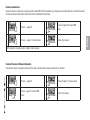
İlgili makaleler
Diğer belgeler
-
Genius Blizzard 500C 900C Kullanma talimatları
-
Genius Blizzard 400C 800C Kullanma talimatları
-
GGM Gastro EQI39 El kitabı
-
-
Yamaha CSP-150 El kitabı
-
-
-
BFT CLONIX1-2 Kullanım kılavuzu
-
Chamberlain LiftMaster LM60 and LM80 El kitabı