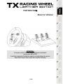
Thrustmaster TX leather edition Kullanım kılavuzu
- Tip
- Kullanım kılavuzu

- USER MANUAL
- MANUEL DE L’UTILISATEUR
- BENUTZERHANDBUCH
- HANDLEIDING
- MANUALE D’USO
- MANUAL DEL USUARIO
- MANUAL DO UTILIZADOR
РУКОВОДСТВО ПОЛЬЗОВАТЕЛЯ
ΕΓΧΕΙΡΙΙΟ ΧΡΗΣΗΣ
KULLANIM KILAVUZU
INSTRUKCJA OBSŁUGI

1/24
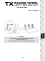
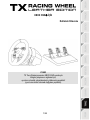
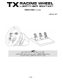
FOR XBOX ONE
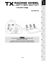
User Manual
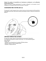
WARNING:
To ensure that your TX Racing Wheel functions correctly
with games for XBOX ONE,
you may be required to install the games' automatic updates
(available when your games console is connected to the Internet).

2/24
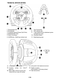
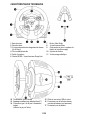
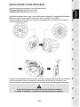
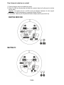
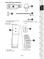
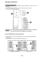
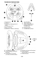
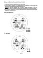
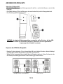
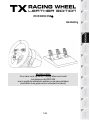
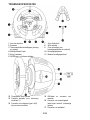
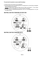
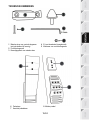
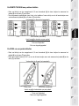
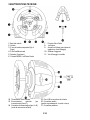
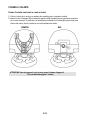
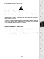
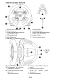
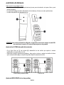
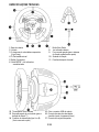
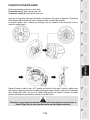
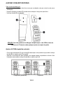
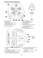
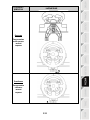
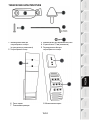
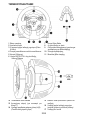
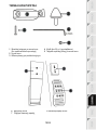
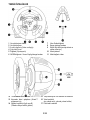
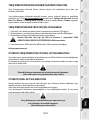
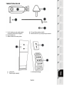
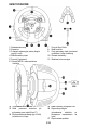
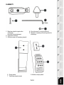
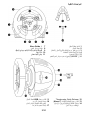
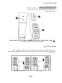
TECHNICAL SPECIFICATIONS
1 Racing wheel base
2 Racing wheel
3 2 sequential gear shift levers (Up & Down)
4 Multidirectional D-Pad
5 Switch (3 positions)
6 MODE button + Red/Green indicator light
7 Xbox Guide button
8 White indicator light
9 Large threaded hole (for attachment system
and tightening screw)
10 Attachment system
11 Metal fastening screw
12 Thrustmaster Quick Release
13 Controller pairing
(for Kinect™
detection)
14 Mains supply connector (type A or B)
(Varies from one country to another)
15 Racing wheel USB cable and connector
16 Gearbox connector
(sold separately, forthcoming release)
17 Pedal set connector

3/24
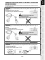
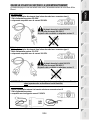
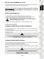
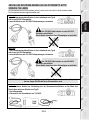
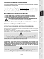
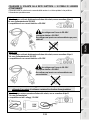
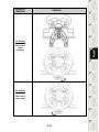
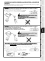
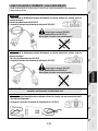
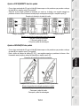
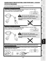
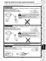
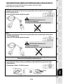
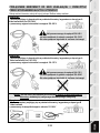
CONNECTING THE RACING WHEEL TO THE MAINS = PLEASE READ
BEFORE PROCEEDING!
Your racing wheel's power supply varies according to the country where you purchased your device.
The mains supply can be:
Internal, with:
* A power supply unit located directly inside the racing wheel's base, with a type A
connector
*A 220-240V mains power supply cable
= compatible only with a 220-240V electrical supply.
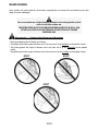
Never connect the 220-240V cable
to a 100-130V power outlet!
Never connect this cable to a mains power adapter!
Internal, with:
* A power supply unit located directly inside the racing wheel's base, with a type A
connector
*A 100-125V power supply cable
= compatible only with a 100-125V electrical supply.
Never connect the 100-125V cable
to a 220-240V power outlet!
Never connect this cable to a mains power adapter!
IMPORTANT: if you do not know which voltage is supplied in the area in which you are
using your racing wheel, please refer to your local electricity supplier.
External, with:
* An external power supply unit located on the racing wheel's base, with a type B connector
* A mains power supply cable
= compatible with all supply voltages, 110-240V.

4/24
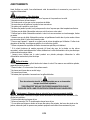
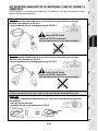
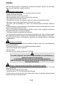
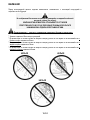
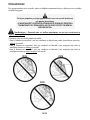
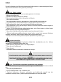
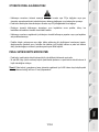
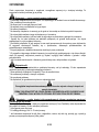
WARNINGS
Before you use this product, please read this documentation carefully and keep it safe should you need to
consult it later.
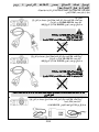
Warning – Electric shock
* Store the product in a dry location and do not expose it to dust or sunlight.
* Respect the connection direction.
* Do not twist or pull the connectors and cables.
* Do not spill any liquid on the product or its connectors.
* Do not short-circuit the product.
* Never dismantle the product; do not throw it onto a fire and do not expose it to high temperatures.
* Do not use a power supply cable other than the one provided with your racing wheel.
* Do not use the mains power supply cable if the cable or the connectors are damaged, split or broken.
* Make sure that the mains power cable is properly inserted into the power outlet and the connector
located on the rear face of the racing wheel's base.
* Do not open. No user replaceable parts inside. Refer servicing to manufacturer, specified agency or
qualified technician.
* Only use attachments/accessories specified by the manufacturer.
* If the steering wheel is operating unusually (if it is emitting any abnormal sounds, heat or odors), stop
using it immediately, disconnect the power cable from the socket and disconnect the other cables.
* If you are not going to be using the steering wheel for an extended period, disconnect the mains adaptor
from the wall socket.
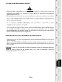
Air vents
Make sure that you do not block any of the air vents on the steering wheel base. For optimum ventilation,
respect the points below:
* Position the base at least 10 cm away from any wall surfaces.
* Do not place the base in any tight spaces.
* Do not cover the base.
* Do not let any dust build up on the air vents.
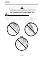
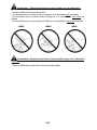
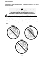
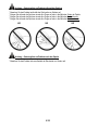
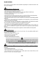
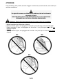
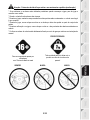
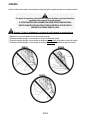
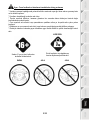
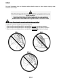
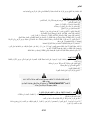
For safety reasons, never use the pedal set with bare feet or while wearing
only socks on your feet.
THRUSTMASTER
®
DISCLAIMS ALL RESPONSIBILITY IN THE EVENT OF
INJURY RESULTING FROM USE OF THE PEDAL SET WITHOUT SHOES.
Warning – Injuries due to force feedback and repeated movements
Playing with a force-feedback steering wheel may cause muscle or joint pain. To avoid any problems:
* Avoid lengthy gaming periods.
* Take 10 to 15 minute breaks after each hour of play.
* If you feel any fatigue or pain in your hands, wrists, arms, feet or legs, stop playing and rest for a few
hours before you start playing again.

5/24
Warning – Injuries due to force feedback and repeated movements (suite)
* If the symptoms or pain indicated above persist when you start playing again, stop playing and
consult your doctor.
* Keep out of children’s reach.
* During games, always leave both hands correctly positioned on the steering wheel without completely
letting go.
* During gameplay, never place your hands or your fingers under the pedals or anywhere near the
pedal set.
* During calibration and gameplay, never place your hand or your arm through the openings in the
racing wheel.
* Check the steering wheel base is carefully clamped as per manual’s instructions.
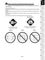
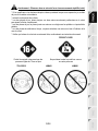
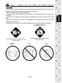
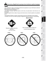
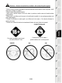
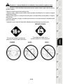
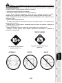
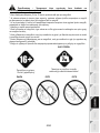
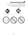
To be handled only by users
16 years of age or older
HEAVY PRODUCT
Be careful not to drop the product on
yourself or on anyone else!
ALWAYS NEVER NEVER

6/24
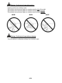
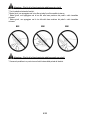
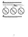
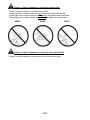
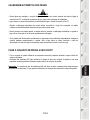
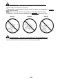
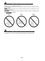
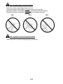
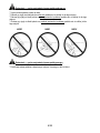
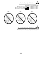
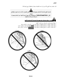
Warning – Pedal set pinch hazard when playing
* Keep the pedal set out of children’s reach.
* When playing, never place your fingers on or anywhere near the sides of the pedals.
* When playing, never leave your fingers on or anywhere near the pedals' rear base.
* When playing, never place your fingers on or anywhere near the pedals' front base.
NEVER NEVER NEVER
Warning – Pedal set pinch hazard when not playing
* Store the pedal set in a safe place, and keep it out of children’s reach.

7/24
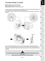
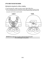
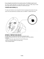
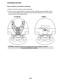
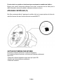
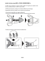
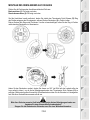
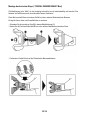
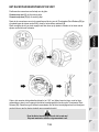
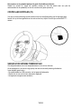
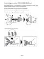
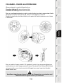
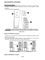
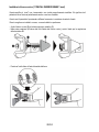
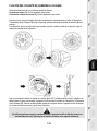
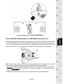
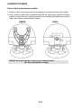
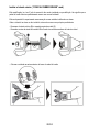
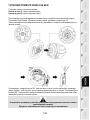
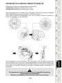
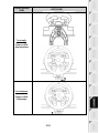
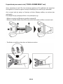
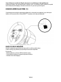
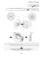
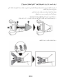
ATTACHING THE WHEEL TO ITS BASE
Align the connector locations using the arrows:
Base (1) connector: Arrow pointing upwards
Racing wheel (2) connector: Arrow pointing upwards
Once the connectors are correctly positioned, simply rotate the Thrustmaster Quick Release (12) device's
ring counterclockwise, while holding the racing wheel (2) in position.
Then, tighten the ring as much as you can; to do so, hold the ring in position and rotate the racing wheel
clockwise.
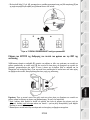
Once you have installed the wheel, rotate it 180° (when facing the wheel, the logo should be upside
down) to access the small attachment screw located on the Thrustmaster Quick Release (12) device. Use
a large cross-slot screwdriver to tighten the small attachment screw (do not use excessive force), turning
it clockwise.
Do not use excessive force when screwing the small attachment screw (using a cross-slot
screwdriver)!
Stop turning the screw as soon as you feel some resistance.

8/24
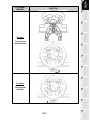
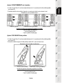
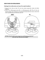
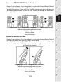
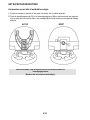
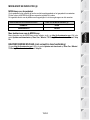
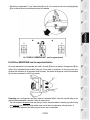
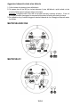
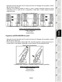
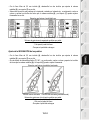
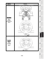
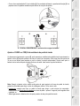
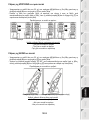
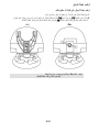
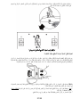
ATTACHING THE RACING WHEEL
Attaching the racing wheel to a table or a desktop
1. Place the racing wheel on a table or any other horizontal, flat and stable surface.
2. Insert the fastening screw (11) in the attachment system (10), then tighten the device by turning
the screw counterclockwise, so that it feeds into the large threaded hole (9) located beneath the
racing wheel, until the device is perfectly stable.
ALWAYS NEVER
WARNING: Never tighten the screw alone, without the attachment system!
(This could damage the racing wheel).

9/24
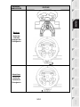
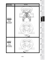
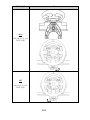
ATTACHMENT /
REMOVAL
DIRECTION
To tighten:
Turn the screw
counterclockwise
To release:
Turn the screw
clockwise

10/24
Attaching the racing wheel's base to a cockpit
1. Place the racing wheel's base on the cockpit shelf.
2. Drive two M6 screws (not included) through the cockpit shelf, then feed them into the two small
threaded holes located beneath the racing wheel.
Important: The length of the M6 screws should not exceed the thickness of the shelf + 12 mm;
longer screws could cause damage to internal components located in the racing wheel's base.
3. If required, tighten the standard attachment system by inserting the fastening screw in the large
threaded hole.
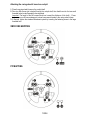
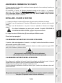
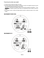
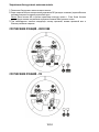
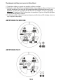
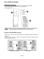
XBOX ONE MAPPING
PC MAPPING

11/24
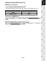
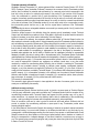
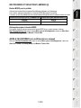
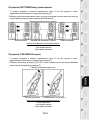
UPGRADING YOUR RACING WHEEL'S FIRMWARE
The firmware included in your racing wheel's base can be upgraded to a more recent version featuring
product enhancements.
To display the firmware version that your racing wheel is currently running and upgrade it if required:
on PC, connect to http://ts.thrustmaster.com. In the Updates and downloads section, click Xbox
One / Wheels / TX Racing Wheel, then select Driver / Firmware and follow the instructions
describing the download and setup procedure.
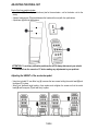
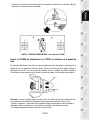
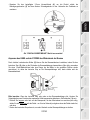
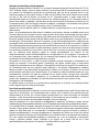
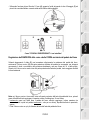
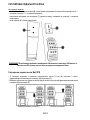
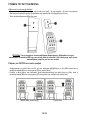
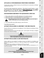
SETTING UP THE RACING WHEEL FOR THE XBOX ONE
1. Connect the pedal set to the connector (17) located at the back of the racing wheel's base.
2. Connect the power supply cable to the connector (14) located at the back of the racing wheel's
base.
3. Connect the power supply cable to a mains outlet with proper voltage specifications.
For more information about this, please refer to the CONNECTING THE RACING
WHEEL TO THE MAINS section, on page 3 in this manual.
4. Connect the racing wheel's USB connector (15) to one of the console's USB ports.
You are now ready to race!
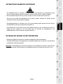
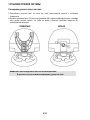
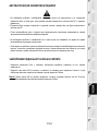
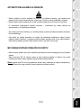
AUTOMATIC RACING WHEEL AND PEDAL SET CALIBRATION
The racing wheel automatically self-calibrates when you connect the racing wheel to the mains and the
racing wheel's USB connector to the console.
During this phase, the racing wheel will rotate quickly towards the left and the right, covering a 900
degree angle, before stopping at the center.
WARNING:
Never touch the racing wheel during the self-calibration phase!
(This could cause an incorrect calibration and/or personal injuries).
AUTOMATIC CALIBRATION OF THE PEDAL SET
Never connect the pedal set to the racing wheel's base (or disconnect it from the base) when it is
connected to the console or during gameplay (this could cause incorrect calibration).
Always connect the pedal set before connecting the racing wheel to the console.
Once the racing wheel's calibration is done and the game has been launched, the pedals are
automatically calibrated after a few presses.
WARNING:
Never press the pedals
during the racing wheel's self-calibration phase or while a game is loading!
(This could cause incorrect calibration)

12/24
If your racing wheel and pedal set do not operate correctly, or if calibration seems incorrect:
Turn off your console, disconnect your racing wheel entirely, reconnect all cables (using the mains
power supply cable and pedal set), then restart your console and your game.
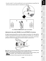
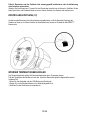
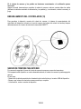
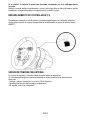
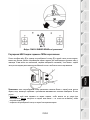
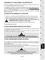
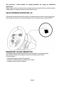
CONTROLLER PAIRING (13)
To ensure correct detection of your racing wheel, the device's controller pairing (located on the upper
section of the racing wheel's base) must always remain in the KINECT™ camera's field of vision.
INTERNAL TEMPERATURE SENSOR
For safety reasons, the racing wheel's base features a temperature sensor.
If the device's temperature becomes too high, your racing wheel can shut down suddenly.
In this event:
- Unplug the mains power supply cable and the device's USB connector.
- Wait for the racing wheel's base to cool down entirely.
- Then, reconnect the device.

13/24
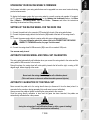
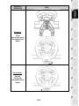
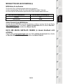
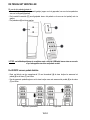
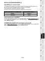
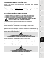
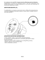
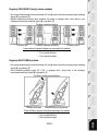
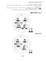
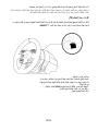
MODE BUTTON AND INDICATOR LIGHT (6)
MODE button for the pedal set
You can electronically swap the accelerator and clutch pedals.
To do so, simply press the MODE button (6) for 2 seconds.
The racing wheel's internal memory stores whether the pedals have been swapped around or not.
ACCELERATOR AND CLUTCH PEDALS
Color of the MODE indicator light (6)
NORMAL
RED
SWAPPED AROUND
GREEN
Other hints for the MODE button
To learn more about MODE button and indicator light, please visit http://ts.thrustmaster.com; in the
Updates and downloads section, click Xbox One / Wheels / TX Racing Wheel, then select Manual /
Help file.
HELP FILES AND FAQS (not stated in this manual)
Please access http://ts.thrustmaster.com; in the Updates and downloads section, click Xbox One /
Wheels / TX Racing Wheel, then select Manual / Help file.

14/24

15/24
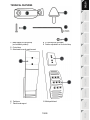
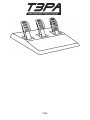
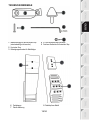
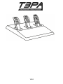
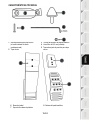
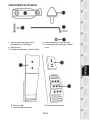
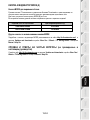
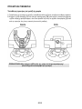
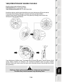
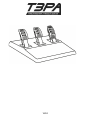
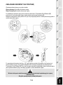
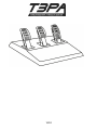
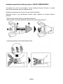
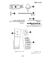
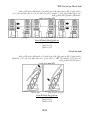
TECHNICAL FEATURES
1 Metal support for conical stop
(not installed by default)
2 Conical stop
3 Attachment screw for metal support
4 2.5 mm Allen key (included)
5 Position adjustment nut for conical stop
6 Pedal arm
7 Plastic head support
8 Metal pedal head

16/24
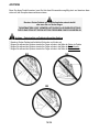
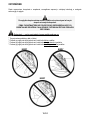
WARNING
Before using this product, be sure to read these instructions carefully and save them for future reference.
For safety reasons, never use the pedal set with bare feet or while wearing
only socks on your feet.
THRUSTMASTER® DISCLAIMS ALL RESPONSIBILITY IN THE EVENT OF
INJURY RESULTING FROM USE OF THE PEDAL SET WITHOUT SHOES.
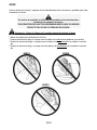
Warning – Pedal set pinching hazard during gaming sessions
* Keep the pedal set out of the reach of children.
* During gaming sessions, never place your fingers or thumbs on or near the sides of the pedals.
* During gaming sessions, never place your fingers or thumbs on or near the rear base of the pedals.
* During gaming sessions, never place your fingers or thumbs on or near the front base of the pedals.
NEVER
NEVER
NEVER

17/24
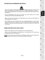
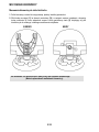
AUTOMATIC CALIBRATION OF PEDALS
IMPORTANT:
- Never connect or disconnect the pedal set from the base of the wheel when the wheel is
connected to the console or PC, or during gaming sessions, to avoid calibration problems.
= Always connect the pedal set to the wheel before connecting the wheel to the console or PC.
- Once the wheel has self-calibrated and the game has started, the pedals automatically calibrate
themselves after being pressed a few times.
- Never press on the pedals when the wheel is self-calibrating or when your game is starting up, to
avoid calibration problems.
- If the pedals are not functioning correctly or appear to be improperly calibrated, power off your
console, completely disconnect your wheel, then reconnect all of the cables (including the power
supply cable and the pedal set cable), power the console back on and restart your game.
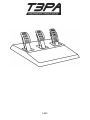
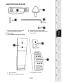
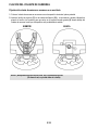
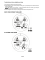
ATTACHING THE PEDAL SET TO A COCKPIT
- Attach the pedal set using the small screw threads located on the underside of the pedal set.
- Screw two M6 screws (not included) into the cockpit’s pedal support plate and into the two small
screw threads located on the underside of the pedal set.
Important: The length of the two M6 screws must not exceed the thickness of the cockpit’s pedal
support plate plus an additional 10 mm, to avoid damaging the pedal set’s internal components.

18/24
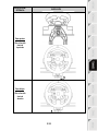
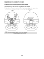
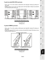
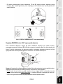
ADJUSTING THE PEDAL SET
Each of the three pedals includes:
- A metal head (8) with multiple perforations (nine for the accelerator – six for the brake – six for the
clutch).
- A plastic head support (7) (placed between the head and the arm) with four perforations.
- A pedal arm (6) with two perforations.
ATTENTION: To avoid any calibration problems, be sure to always disconnect your wheel’s
USB cable from the console or PC before making any adjustments to your pedal set.
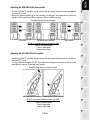
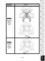
Adjusting the HEIGHT of the accelerator pedal
- Using the included 2.5 mm Allen key (4), unscrew the two screws holding the metal head (8) and
its support (7) in place.
- Select your preferred height position, then replace and re-tighten the screws so that the metal
head (8) and its support (7) are held firmly in place.
Low position (default)
High position

19/24
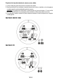
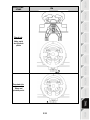
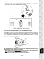
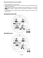
Adjusting the SPACING of the three pedals
- Using the included 2.5 mm Allen key (4), unscrew the two screws holding the metal head (8) and
its support (7) in place.
- Select your preferred position (to the left, centered, or to the right), then replace and re-tighten the
screws so that the metal head (8) and its support (7) are held firmly in place.
Examples illustrating the brake pedal:
Left position Centered position (default) Right position
Number of possible spacing positions per pedal:
- Three for accelerator pedal
- Three for brake pedal
- Three for clutch pedal
Adjusting the INCLINATION of the pedals
- Using the included 2.5 mm Allen key (4), unscrew the two screws holding the metal head (8) and
its support (7) in place.
- Turn the plastic head support (7) 180°, then replace and re-tighten the screws so that the metal
head (8) and its support (7) are held firmly in place.
Examples illustrating the accelerator pedal:
Less inclined position More inclined position (default)
Number of possible inclination positions per pedal:
- Two for accelerator pedal
- Two for brake pedal
- Two for clutch pedal
Sayfa yükleniyor...
Sayfa yükleniyor...
Sayfa yükleniyor...
Sayfa yükleniyor...
Sayfa yükleniyor...
Sayfa yükleniyor...
Sayfa yükleniyor...
Sayfa yükleniyor...
Sayfa yükleniyor...
Sayfa yükleniyor...
Sayfa yükleniyor...
Sayfa yükleniyor...
Sayfa yükleniyor...
Sayfa yükleniyor...
Sayfa yükleniyor...
Sayfa yükleniyor...
Sayfa yükleniyor...
Sayfa yükleniyor...
Sayfa yükleniyor...
Sayfa yükleniyor...
Sayfa yükleniyor...
Sayfa yükleniyor...
Sayfa yükleniyor...
Sayfa yükleniyor...
Sayfa yükleniyor...
Sayfa yükleniyor...
Sayfa yükleniyor...
Sayfa yükleniyor...
Sayfa yükleniyor...
Sayfa yükleniyor...
Sayfa yükleniyor...
Sayfa yükleniyor...
Sayfa yükleniyor...
Sayfa yükleniyor...
Sayfa yükleniyor...
Sayfa yükleniyor...
Sayfa yükleniyor...
Sayfa yükleniyor...
Sayfa yükleniyor...
Sayfa yükleniyor...
Sayfa yükleniyor...
Sayfa yükleniyor...
Sayfa yükleniyor...
Sayfa yükleniyor...
Sayfa yükleniyor...
Sayfa yükleniyor...
Sayfa yükleniyor...
Sayfa yükleniyor...
Sayfa yükleniyor...
Sayfa yükleniyor...
Sayfa yükleniyor...
Sayfa yükleniyor...
Sayfa yükleniyor...
Sayfa yükleniyor...
Sayfa yükleniyor...
Sayfa yükleniyor...
Sayfa yükleniyor...
Sayfa yükleniyor...
Sayfa yükleniyor...
Sayfa yükleniyor...
Sayfa yükleniyor...
Sayfa yükleniyor...
Sayfa yükleniyor...
Sayfa yükleniyor...
Sayfa yükleniyor...
Sayfa yükleniyor...
Sayfa yükleniyor...
Sayfa yükleniyor...
Sayfa yükleniyor...
Sayfa yükleniyor...
Sayfa yükleniyor...
Sayfa yükleniyor...
Sayfa yükleniyor...
Sayfa yükleniyor...
Sayfa yükleniyor...
Sayfa yükleniyor...
Sayfa yükleniyor...
Sayfa yükleniyor...
Sayfa yükleniyor...
Sayfa yükleniyor...
Sayfa yükleniyor...
Sayfa yükleniyor...
Sayfa yükleniyor...
Sayfa yükleniyor...
Sayfa yükleniyor...
Sayfa yükleniyor...
Sayfa yükleniyor...
Sayfa yükleniyor...
Sayfa yükleniyor...
Sayfa yükleniyor...
Sayfa yükleniyor...
Sayfa yükleniyor...
Sayfa yükleniyor...
Sayfa yükleniyor...
Sayfa yükleniyor...
Sayfa yükleniyor...
Sayfa yükleniyor...
Sayfa yükleniyor...
Sayfa yükleniyor...
Sayfa yükleniyor...
Sayfa yükleniyor...
Sayfa yükleniyor...
Sayfa yükleniyor...
Sayfa yükleniyor...
Sayfa yükleniyor...
Sayfa yükleniyor...
Sayfa yükleniyor...
Sayfa yükleniyor...
Sayfa yükleniyor...
Sayfa yükleniyor...
Sayfa yükleniyor...
Sayfa yükleniyor...
Sayfa yükleniyor...
Sayfa yükleniyor...
Sayfa yükleniyor...
Sayfa yükleniyor...
Sayfa yükleniyor...
Sayfa yükleniyor...
Sayfa yükleniyor...
Sayfa yükleniyor...
Sayfa yükleniyor...
Sayfa yükleniyor...
Sayfa yükleniyor...
Sayfa yükleniyor...
Sayfa yükleniyor...
Sayfa yükleniyor...
Sayfa yükleniyor...
Sayfa yükleniyor...
Sayfa yükleniyor...
Sayfa yükleniyor...
Sayfa yükleniyor...
Sayfa yükleniyor...
Sayfa yükleniyor...
Sayfa yükleniyor...
Sayfa yükleniyor...
Sayfa yükleniyor...
Sayfa yükleniyor...
Sayfa yükleniyor...
Sayfa yükleniyor...
Sayfa yükleniyor...
Sayfa yükleniyor...
Sayfa yükleniyor...
Sayfa yükleniyor...
Sayfa yükleniyor...
Sayfa yükleniyor...
Sayfa yükleniyor...
Sayfa yükleniyor...
Sayfa yükleniyor...
Sayfa yükleniyor...
Sayfa yükleniyor...
Sayfa yükleniyor...
Sayfa yükleniyor...
Sayfa yükleniyor...
Sayfa yükleniyor...
Sayfa yükleniyor...
Sayfa yükleniyor...
Sayfa yükleniyor...
Sayfa yükleniyor...
Sayfa yükleniyor...
Sayfa yükleniyor...
Sayfa yükleniyor...
Sayfa yükleniyor...
Sayfa yükleniyor...
Sayfa yükleniyor...
Sayfa yükleniyor...
Sayfa yükleniyor...
Sayfa yükleniyor...
Sayfa yükleniyor...
Sayfa yükleniyor...
Sayfa yükleniyor...
Sayfa yükleniyor...
Sayfa yükleniyor...
Sayfa yükleniyor...
Sayfa yükleniyor...
Sayfa yükleniyor...
Sayfa yükleniyor...
Sayfa yükleniyor...
Sayfa yükleniyor...
Sayfa yükleniyor...
Sayfa yükleniyor...
Sayfa yükleniyor...
Sayfa yükleniyor...
Sayfa yükleniyor...
Sayfa yükleniyor...
Sayfa yükleniyor...
Sayfa yükleniyor...
Sayfa yükleniyor...
Sayfa yükleniyor...
Sayfa yükleniyor...
Sayfa yükleniyor...
Sayfa yükleniyor...
Sayfa yükleniyor...
Sayfa yükleniyor...
Sayfa yükleniyor...
Sayfa yükleniyor...
Sayfa yükleniyor...
Sayfa yükleniyor...
Sayfa yükleniyor...
Sayfa yükleniyor...
Sayfa yükleniyor...
Sayfa yükleniyor...
Sayfa yükleniyor...
Sayfa yükleniyor...
Sayfa yükleniyor...
Sayfa yükleniyor...
Sayfa yükleniyor...
Sayfa yükleniyor...
Sayfa yükleniyor...
Sayfa yükleniyor...
Sayfa yükleniyor...
Sayfa yükleniyor...
Sayfa yükleniyor...
Sayfa yükleniyor...
Sayfa yükleniyor...
Sayfa yükleniyor...
Sayfa yükleniyor...
Sayfa yükleniyor...
Sayfa yükleniyor...
Sayfa yükleniyor...
Sayfa yükleniyor...
Sayfa yükleniyor...
Sayfa yükleniyor...
Sayfa yükleniyor...
Sayfa yükleniyor...
Sayfa yükleniyor...
Sayfa yükleniyor...
Sayfa yükleniyor...
Sayfa yükleniyor...
Sayfa yükleniyor...
Sayfa yükleniyor...
Sayfa yükleniyor...
Sayfa yükleniyor...
Sayfa yükleniyor...
Sayfa yükleniyor...
Sayfa yükleniyor...
Sayfa yükleniyor...
Sayfa yükleniyor...
Sayfa yükleniyor...
Sayfa yükleniyor...
Sayfa yükleniyor...
Sayfa yükleniyor...
Sayfa yükleniyor...
Sayfa yükleniyor...
Sayfa yükleniyor...
Sayfa yükleniyor...
Sayfa yükleniyor...
Sayfa yükleniyor...
Sayfa yükleniyor...
Sayfa yükleniyor...
Sayfa yükleniyor...
Sayfa yükleniyor...
Sayfa yükleniyor...
Sayfa yükleniyor...
Sayfa yükleniyor...
Sayfa yükleniyor...
Sayfa yükleniyor...
Sayfa yükleniyor...
Sayfa yükleniyor...
Sayfa yükleniyor...
Sayfa yükleniyor...
Sayfa yükleniyor...
Sayfa yükleniyor...
Sayfa yükleniyor...
Sayfa yükleniyor...
Sayfa yükleniyor...
Sayfa yükleniyor...
Sayfa yükleniyor...
Sayfa yükleniyor...
Sayfa yükleniyor...
-
 1
1
-
 2
2
-
 3
3
-
 4
4
-
 5
5
-
 6
6
-
 7
7
-
 8
8
-
 9
9
-
 10
10
-
 11
11
-
 12
12
-
 13
13
-
 14
14
-
 15
15
-
 16
16
-
 17
17
-
 18
18
-
 19
19
-
 20
20
-
 21
21
-
 22
22
-
 23
23
-
 24
24
-
 25
25
-
 26
26
-
 27
27
-
 28
28
-
 29
29
-
 30
30
-
 31
31
-
 32
32
-
 33
33
-
 34
34
-
 35
35
-
 36
36
-
 37
37
-
 38
38
-
 39
39
-
 40
40
-
 41
41
-
 42
42
-
 43
43
-
 44
44
-
 45
45
-
 46
46
-
 47
47
-
 48
48
-
 49
49
-
 50
50
-
 51
51
-
 52
52
-
 53
53
-
 54
54
-
 55
55
-
 56
56
-
 57
57
-
 58
58
-
 59
59
-
 60
60
-
 61
61
-
 62
62
-
 63
63
-
 64
64
-
 65
65
-
 66
66
-
 67
67
-
 68
68
-
 69
69
-
 70
70
-
 71
71
-
 72
72
-
 73
73
-
 74
74
-
 75
75
-
 76
76
-
 77
77
-
 78
78
-
 79
79
-
 80
80
-
 81
81
-
 82
82
-
 83
83
-
 84
84
-
 85
85
-
 86
86
-
 87
87
-
 88
88
-
 89
89
-
 90
90
-
 91
91
-
 92
92
-
 93
93
-
 94
94
-
 95
95
-
 96
96
-
 97
97
-
 98
98
-
 99
99
-
 100
100
-
 101
101
-
 102
102
-
 103
103
-
 104
104
-
 105
105
-
 106
106
-
 107
107
-
 108
108
-
 109
109
-
 110
110
-
 111
111
-
 112
112
-
 113
113
-
 114
114
-
 115
115
-
 116
116
-
 117
117
-
 118
118
-
 119
119
-
 120
120
-
 121
121
-
 122
122
-
 123
123
-
 124
124
-
 125
125
-
 126
126
-
 127
127
-
 128
128
-
 129
129
-
 130
130
-
 131
131
-
 132
132
-
 133
133
-
 134
134
-
 135
135
-
 136
136
-
 137
137
-
 138
138
-
 139
139
-
 140
140
-
 141
141
-
 142
142
-
 143
143
-
 144
144
-
 145
145
-
 146
146
-
 147
147
-
 148
148
-
 149
149
-
 150
150
-
 151
151
-
 152
152
-
 153
153
-
 154
154
-
 155
155
-
 156
156
-
 157
157
-
 158
158
-
 159
159
-
 160
160
-
 161
161
-
 162
162
-
 163
163
-
 164
164
-
 165
165
-
 166
166
-
 167
167
-
 168
168
-
 169
169
-
 170
170
-
 171
171
-
 172
172
-
 173
173
-
 174
174
-
 175
175
-
 176
176
-
 177
177
-
 178
178
-
 179
179
-
 180
180
-
 181
181
-
 182
182
-
 183
183
-
 184
184
-
 185
185
-
 186
186
-
 187
187
-
 188
188
-
 189
189
-
 190
190
-
 191
191
-
 192
192
-
 193
193
-
 194
194
-
 195
195
-
 196
196
-
 197
197
-
 198
198
-
 199
199
-
 200
200
-
 201
201
-
 202
202
-
 203
203
-
 204
204
-
 205
205
-
 206
206
-
 207
207
-
 208
208
-
 209
209
-
 210
210
-
 211
211
-
 212
212
-
 213
213
-
 214
214
-
 215
215
-
 216
216
-
 217
217
-
 218
218
-
 219
219
-
 220
220
-
 221
221
-
 222
222
-
 223
223
-
 224
224
-
 225
225
-
 226
226
-
 227
227
-
 228
228
-
 229
229
-
 230
230
-
 231
231
-
 232
232
-
 233
233
-
 234
234
-
 235
235
-
 236
236
-
 237
237
-
 238
238
-
 239
239
-
 240
240
-
 241
241
-
 242
242
-
 243
243
-
 244
244
-
 245
245
-
 246
246
-
 247
247
-
 248
248
-
 249
249
-
 250
250
-
 251
251
-
 252
252
-
 253
253
-
 254
254
-
 255
255
-
 256
256
-
 257
257
-
 258
258
-
 259
259
-
 260
260
-
 261
261
-
 262
262
-
 263
263
-
 264
264
-
 265
265
-
 266
266
-
 267
267
-
 268
268
-
 269
269
-
 270
270
-
 271
271
-
 272
272
-
 273
273
-
 274
274
-
 275
275
-
 276
276
-
 277
277
-
 278
278
-
 279
279
-
 280
280
-
 281
281
-
 282
282
-
 283
283
-
 284
284
-
 285
285
-
 286
286
-
 287
287
-
 288
288
-
 289
289


Thrustmaster TX leather edition Kullanım kılavuzu
- Tip
- Kullanım kılavuzu
diğer dillerde
İlgili makaleler
-
Thrustmaster 2969097 2961061 Kullanım kılavuzu
-
-
Thrustmaster 4469024 Kullanım kılavuzu
-
-
-
-
-
Thrustmaster t150 Kullanım kılavuzu
-
-
Thrustmaster 2960726 Kullanım kılavuzu