

1/20
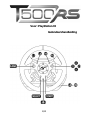
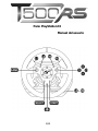
For: PlayStation®3
User Manual

2/20
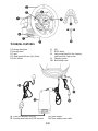
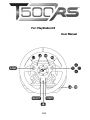
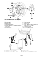
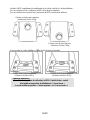
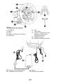
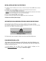
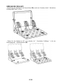
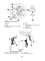
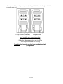
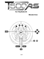
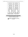
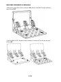
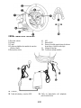
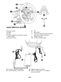
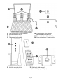
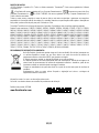
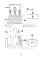
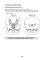
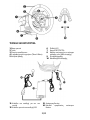
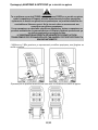
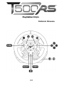
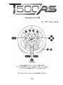
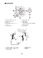
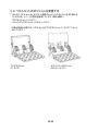
TECHNICAL FEATURES
1 Steering wheel base
2 Steering wheel
3 D-pad
4 2 digital gearshift levers (Up & Down)
5 Action buttons
6 LED
7 MODE button
8 Large screw thread (for the clamping
system and the clamp screw)
9 Clamping system
10 Metal clamp screw
11 Pedal set cable and connector
12 Steering wheel cable and USB connector
13 Mains adaptor
14 Mains adaptor power cable

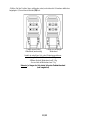
3/20
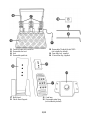
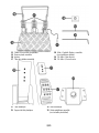
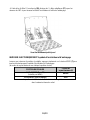
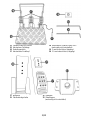
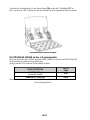
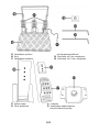
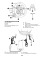
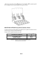
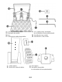
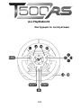
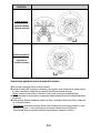
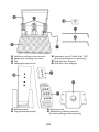
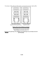
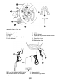
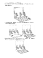
11 Pedal set cable and connector
15 Removable foot rest
16 Arch
17 Removable pedal set
18 Removable “Realistic Brake” MOD
(not installed by default)
19 2mm Allen key, supplied
20 2.5mm Allen key, supplied
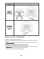
17 Metal head
21 Plastic Head Support
22 Pedal arm
23 Removable metal stop
(not installed by default)

4/20
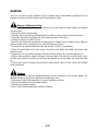
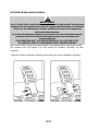
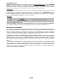
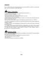
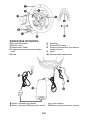
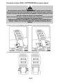
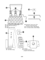
WARNING
Before you use this product, please read this documentation carefully and keep it safe should you need to
consult it later.
* Store the product in a dry location and do not expose it to dust or sunlight.
Warning – Electric shock
* Respect the connection direction.
* Do not twist or pull the connectors and cables.
* Do not spill any liquid on the product or its connectors.
* Do not short-circuit the product.
* Never dismantle the product (except to adjust the pedal set if necessary); do not throw it onto a fire and
do not expose it to high temperatures.
* Do not use any adaptors other than the mains adaptor provided with the “T500 RS”.
* Do not use the mains adaptor if its connectors or cables are damaged, split or broken.
* Make sure that the mains adaptor’s power cable is perfectly inserted into the wall socket.
* If the steering wheel is operating unusually (if it is emitting any abnormal sounds, heat or odours), stop
using it immediately, disconnect the power cable from the socket and disconnect the other cables.
* If you are not going to be using the steering wheel for an extended period, disconnect the mains adaptor
from the wall socket.
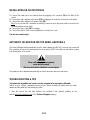
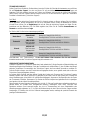
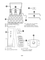
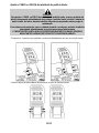
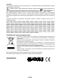
Make sure that you do not block any of the air vents on the steering wheel base. For optimum ventilation,
respect the points below:
Air vents
* Position the base at least 10 cm away from any wall surfaces.
* Do not place the base in any tight spaces.
* Do not cover the base.
* Do not let any dust build up on the air vents.

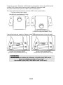
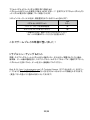
5/20
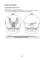
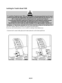
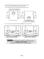
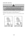
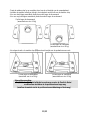
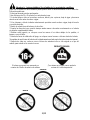
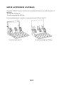
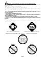
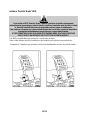
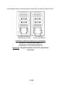
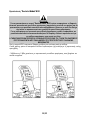
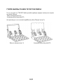
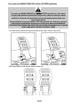
Playing with a force-feedback steering wheel may cause muscle or joint pain. To avoid any problems:
Warning – Injuries due to force feedback and repeated movements
* Avoid lengthy gaming periods.
* Take 10 to 15 minute breaks after each hour of play.
* If you feel any fatigue or pain in your hands, wrists, arms, feet or legs, stop playing and rest for a few
hours before you start playing again.
* If the symptoms or pain indicated above persist when you start playing again, stop playing and
consult your doctor.
* Keep out of children’s reach.
* During games, always leave both hands correctly positioned on the steering wheel without letting it go
completely.
* During game calibration, never place your hand or arm inside the steering wheel.
* Check the steering wheel base is carefully clamped as per manual’s instructions.
* After each use, put the warning notice back in its original place on the wheel’s shaft, to warn any
potential new users.
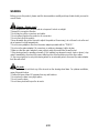
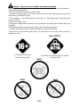
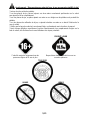
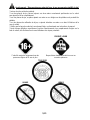
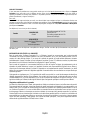
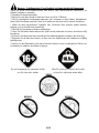
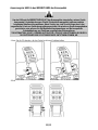
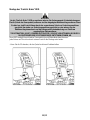
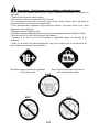
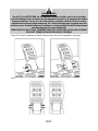
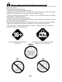
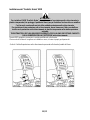
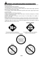
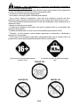
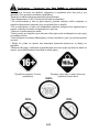
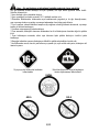
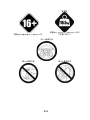
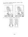
To be handled only by users
16 years of age or older
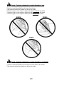
HEAVY PRODUCT
Be careful not to drop the product on yourself
or on anyone else!
ALWAYS
NEVER
NEVER

6/20
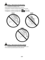
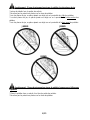
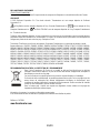
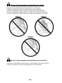
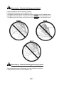
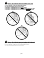
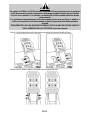
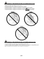
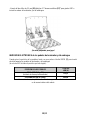
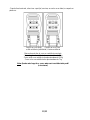
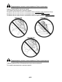
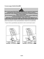
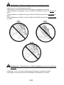
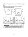
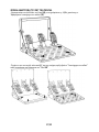
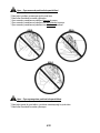
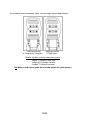
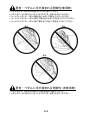
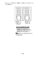
Warning – Pedal set pinch hazard when playing
* Keep the pedal set out of children’s reach.
* Do not remove the protections placed on the pedal arms.
* During games, never place your fingers near the
sides
* During games, never place your fingers near the
of the pedals.
rear base
* During games, never place your fingers near the
of the pedals.
front base
of the pedals.
NEVER
NEVER
NEVER
Warning – Pedal set pinch hazard when not playing
* Store the pedal set in a safe place, and keep it out of children’s reach.
* Do not remove the protections placed on the pedal arms.

7/20
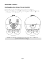
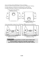
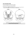
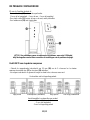
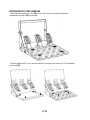
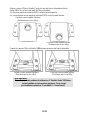
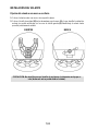
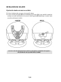
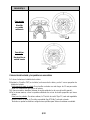
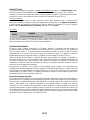
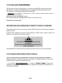
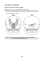
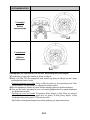
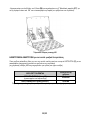
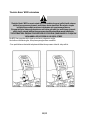
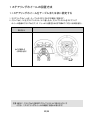
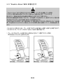
INSTALLING THE WHEEL
Fixing the wheel to a Table or Desk
1. Place the wheel on a table or another flat surface.
2. Place the clamp screw (10) in the table clamp (9) then screw the clamping unit (anti-clockwise)
into the large screw thread (8) located under the wheel until it is perfectly stable.
ALWAYS NEVER
CAUTION: Never screw the clamp screw into the clamping system on its own!
(this may damage the steering wheel).

8/20
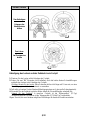
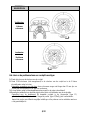
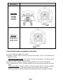
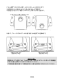
ASSEMBLY /
DISASSEMBLY
To tighten:
Screw
anti-
clockwise
To loosen:
Unscrew
clockwise
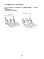
Attaching the steering wheel and pedal set to a cockpit
1. Place the steering wheel on the Cockpit’s tablet.
2. Tighten 2 “M6” screws (not supplied) into the Cockpit table and into the 2 small screw threads
under the wheel.
Important note for the Wheel
3. If necessary, screw in the standard clamping system (into the large screw thread).
: These screws must not be longer than 12mm to avoid damaging
the components inside the base.
4. In the same way, attach the Pedal set using the small screw threads underneath it.
Note for the Pedal set
Do not hesitate to test the different possible settings for more comfort.
: In certain cockpits the “Floor position” (F1 type) will be more user-friendly.
On others the “Suspended position (GT/Rally type)" will be more comfortable.

9/20
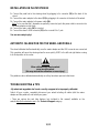
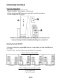
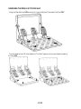
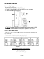
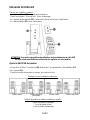
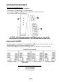
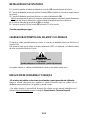
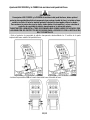
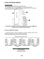
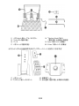
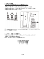
INSTALLATION ON PLAYSTATION®3
1. Connect the pedal set to the steering wheel by plugging in its connector (11) at the back of the
wheel.
2. Connect the mains adaptor to the wheel (13) by plugging in its connector to the back of the wheel.
3. Connect the mains adaptor to its power cable (14).
Note: To be sure that the 2 elements are perfectly connected, push the power cable’s connector into
the mains adaptor socket firmly.
4. Connect the mains cable (14) to a socket.
5. Connect the wheel’s USB connector (12) to the console’s No. 1 port.
You are now ready to play!
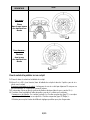
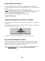
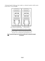
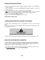
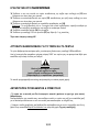
AUTOMATIC CALIBRATION FOR THE WHEEL AND PEDALS
The wheel calibrates itself automatically once the mains adaptor and the USB connector are connected.
This operation will cause the steering wheel to move quickly 1080° to the left and right before coming
to its final position in the center.
When calibrating the steering wheel
CAUTION:
never touch the wheel
(this may mislead the calibration or cause injury).
The pedals are also calibrated automatically once they have been pressed a few times.
TROUBLESHOOTING & TIPS
- My wheel and my pedals don’t work correctly or appear to be improperly calibrated:
Switch off your console, completely disconnect your wheel including all cables (with the mains
adaptor and the pedal set) and restart your game.
- There are various tips and help features (not included in this manual) available on the
website
http://ts.thrustmaster.com in the Technical Support category.

10/20
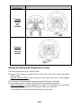
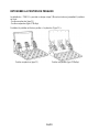
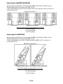
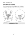
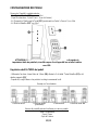
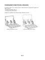
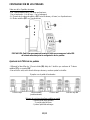
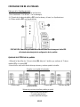
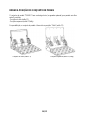
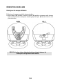
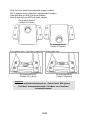
CONFIGURING THE PEDALS
Each of the 3 pedals features
- A “Metal Head (17)” with several perforations
:
(9 for the Accelerator – 6 for the Brake – 6 for the Clutch)
- A “Plastic Head Support (21)” (between the head and the arm) with 4 perforations
- A “Metal Arm (22)” with 4 perforations
CAUTION: To avoid any calibration problems, always disconnect the USB cable
from your steering wheel before adjusting the settings on your pedal set.
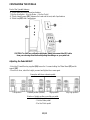
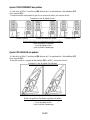
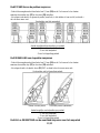
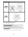
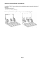
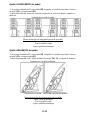
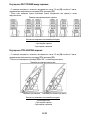
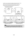
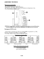
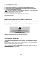
Adjusting the Pedal HEIGHT
- Using the 2.5mm Allen key supplied (20) loosen the 2 screws holding the “Metal Head (17) and its
support (21)”
- Once this is done, select the height you want and tighten the screws again.
Examples with the accelerator pedal:
Low position
Medium position (default)
High position
Very high position
- 4 for the Accelerator pedal
Number of height positions possible per pedal:
- 2 for the Brake pedal
- 2 for the Clutch pedal

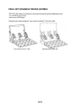
11/20
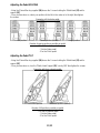
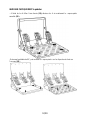
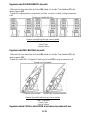
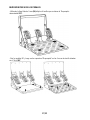
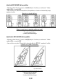
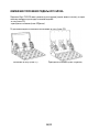
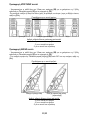
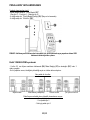
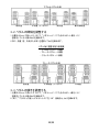
Adjusting the Pedal SPACING
- Using the 2.5mm Allen key supplied (20) loosen the 2 screws holding the “Metal Head (17) and its
support (21)”
- Once you have done so, select your position (to the left, in the center or to the right) then tighten
the screws.
Examples with the brake pedal:
Left position Center position (default) Right position
- 3 for the Accelerator pedal
Number of spacing positions possible per pedal:
- 3 for the Brake pedal
- 3 for the Clutch pedal
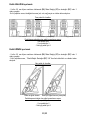
Adjusting the Pedal TILT
- Using the 2.5mm Allen key supplied (20) loosen the 2 screws holding the “Metal Head (17) and its
support (21)”
- Once you have done so, turn the “Plastic Head Support (21)” over by 180° then tighten the screws.
Examples with the accelerator pedal:
Less tilted position More tilted position (default)
- 2 for the Accelerator pedal
Number of tilt positions possible per pedal:
- 2 for the Brake pedal
- 2 for the Clutch pedal

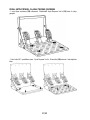
12/20
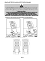
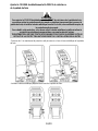
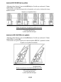
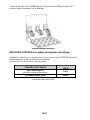
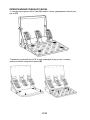
Adjusting the TRAVEL & resistance FORCE for the Brake pedal
To adjust the TRAVEL and resistance FORCE for the Brake pedal, you must remove the
transparent plastic pinch-hazard protector (protecting the brake pedal), and install the
included metal stop. By doing so, you will no longer benefit from the intended protection
against pinch hazards.
CAUTION:
To restore your protection against pinch hazards, you must remove the metal stop and
reinstall the transparent plastic pinch-hazard protector in its former location.
THRUSTMASTER® DISCLAIMS ALL RESPONSIBILITY FOR ANY INJURIES CAUSED BY
REMOVAL OF THE PINCH-HAZARD PROTECTOR OR INSTALLATION OF THE METAL STOP
- Unscrew the 2 screws holding the pinch-hazard protector on the brake pedal arm.
- Install the metal stop (23) at the rear of the brake pedal arm.

13/20
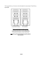
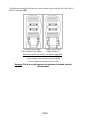
- Select your position (up, in the center or down) then tighten the screws using the 2.5mm Allen key
supplied (20).
Long run position Short run position
& High resistance (default) & Low resistance
Number of possible travel or resistance positions
- Long travel with resistance of around 10Kg (22lbs)
:
- Medium travel with resistance of around 8.5Kg (18.7lbs)
- Short travel with resistance of around 7Kg (15.4lbs)
Note
(and vice versa)
: the longer the travel the higher the pedal resistance

14/20
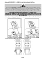
Installing the “Realistic Brake” MOD
To install the “Realistic Brake” MOD, you must remove the transparent plastic pinch-hazard
protector (protecting the brake pedal), and install the included metal stop. By doing so, you
will no longer benefit from the intended protection against pinch hazards.
CAUTION:
To restore your protection against pinch hazards, you must remove the metal stop and
reinstall the transparent plastic pinch-hazard protector in its former location.
THRUSTMASTER® DISCLAIMS ALL RESPONSIBILITY FOR ANY INJURIES CAUSED BY
REMOVAL OF THE PINCH-HAZARD PROTECTOR OR INSTALLATION OF THE METAL STOP
This MOD enables different sensations and resistance when braking.
Each user must decide whether or not to install it according to their preferences.
- Unscrew the 2 screws holding the pinch-hazard protector on the brake pedal arm.

15/20
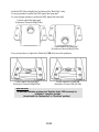
- Install the MOD fully and tightly into the bottom of the “Metal Stop” cavity.
- For strong resistance: position the MOD against the Upper wall.
- For even stronger resistance: position the MOD against the Lower wall.
Position against the Upper wall
(Resistance of around 14Kg/30.8lbs)
Position against the Lower wall
(Resistance of around 16Kg/35.2lbs)
- Once you have done so, tighten the “Metal Stop” (23) at the rear of the pedal arm
Position against the Upper wall Position against the Lower wall
(Resistance of around 14Kg/30.8lbs) (Resistance of around 16Kg/35.2lbs)
To avoid any calibration problems, the “Realistic Brake” MOD must only be
installed in “Long Run” position
Important note:
(do not install it in “Medium Run” or “Short Run” position)

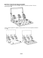
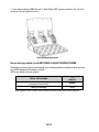
16/20
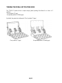
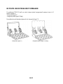
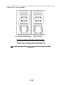
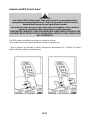
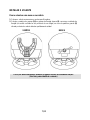
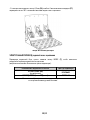
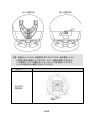
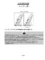
TURNING THE PEDAL SET POSITION OVER
The “T500 RS” pedal set has a unique design (patent pending) that allows for a choice of 2
positions:
- Floor position (F1 type)
- Suspended position (GT/Rally type)
By default, the pedal set is delivered in “Floor” position (F1 type)
Floor position (F1 type) Suspended position (GT/Rally type)

17/20
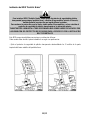
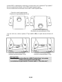
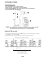
REVERSING THE PEDAL SET PHYSICALLY
- Using the 2mm Allen key (19) loosen the 4 screws holding the “Removable Foot Rest (15)”
- Turn the pedal set over 90° then tighten the "Foot Rest" again on the 4 screw threads located on
the "Arch (16)”

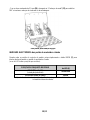
18/20
- Using the 2.5mm Allen key (20) loosen the 3 "Metal Heads (17)” to turn them over 180° and
reverse the Accelerator head and the Clutch head.
You are now ready to play!
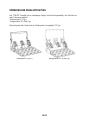
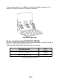
ELECTRONIC REVERSAL for the accelerator & clutch pedals
When you turn over the pedal set position: simply press the MODE button (7) to reverse the
accelerator and clutch pedals electronically
(the LED colour tells you the position you have chosen)
PEDAL SET POSITION
LED (6)
colour
ON THE FLOOR (F1 type)
(installed by default)
RED
SUSPENDED (GT/Rally type) GREEN
Once you have done this the selected position is stored immediately
in the wheel’s internal memory

19/20
TECHNICAL SUPPORT
If you encounter a problem with your product, please go to http://ts.thrustmaster.com and click Technical Support.
From there you will be able to access various utilities (Frequently Asked Questions (FAQ), the latest versions of drivers
and software) that may help to resolve your problem. If the problem persists, you can contact the Thrustmaster
products technical support service (“Technical Support”):
By email:
In order to take advantage of technical support by email, you must first register online. The information you provide will
help the agents to resolve your problem more quickly. Click Registration on the left-hand side of the Technical Support
page and follow the on-screen instructions. If you have already registered, fill in the Username and Password fields
and then click Login.
By telephone:
United
Kingdom
08450800942
Charged
at local rate
Monday to Saturday from 8 a.m. to 7 p.m.
Denmark
80887690
Free
Monday to Saturday from 9 a.m. to 8 p.m.
(English)
Sweden
0200884567
Free
Monday to Saturday from 9 a.m. to 8 p.m.
(English)
Finland
0800 913060
Free
Monday to Saturday from 10 a.m. to 9 p.m.
(English)
Hours of operation and telephone numbers are subject to change. Please visit http://ts.thrustmaster.com for the most
up-to-date Technical Support contact information.
WARRANTY INFORMATION
Worldwide, Guillemot Corporation S.A. (“Guillemot”) warrants to the consumer that this Thrustmaster product will be
free from material defects and manufacturing flaws for a period of two (2) years from the original date of purchase.
Should the product appear to be defective during the warranty period, immediately contact Technical Support, who will
indicate the procedure to follow. If the defect is confirmed, the product must be returned to its place of purchase (or any
other location indicated by Technical Support).
Within the context of this warranty, the consumer’s defective product will, at Technical Support’s option, be either
repaired or replaced. Where authorized by applicable law, the full liability of Guillemot and its subsidiaries (including for
indirect damages) is limited to the repair or replacement of the Thrustmaster product. The consumer’s legal rights with
respect to legislation applicable to the sale of consumer goods are not affected by this warranty.
This warranty shall not apply: (1) if the product has been modified, opened, altered, or has suffered damage as a result
of inappropriate or abusive use, negligence, an accident, normal wear, or any other cause not related to a material
defect or manufacturing flaw; (2) in the event of failure to comply with the instructions provided by Technical Support;
(3) to software not published by Guillemot, said software being subject to a specific warranty provided by its publisher.
Sayfa yükleniyor...
Sayfa yükleniyor...
Sayfa yükleniyor...
Sayfa yükleniyor...
Sayfa yükleniyor...
Sayfa yükleniyor...
Sayfa yükleniyor...
Sayfa yükleniyor...
Sayfa yükleniyor...
Sayfa yükleniyor...
Sayfa yükleniyor...
Sayfa yükleniyor...
Sayfa yükleniyor...
Sayfa yükleniyor...
Sayfa yükleniyor...
Sayfa yükleniyor...
Sayfa yükleniyor...
Sayfa yükleniyor...
Sayfa yükleniyor...
Sayfa yükleniyor...
Sayfa yükleniyor...
Sayfa yükleniyor...
Sayfa yükleniyor...
Sayfa yükleniyor...
Sayfa yükleniyor...
Sayfa yükleniyor...
Sayfa yükleniyor...
Sayfa yükleniyor...
Sayfa yükleniyor...
Sayfa yükleniyor...
Sayfa yükleniyor...
Sayfa yükleniyor...
Sayfa yükleniyor...
Sayfa yükleniyor...
Sayfa yükleniyor...
Sayfa yükleniyor...
Sayfa yükleniyor...
Sayfa yükleniyor...
Sayfa yükleniyor...
Sayfa yükleniyor...
Sayfa yükleniyor...
Sayfa yükleniyor...
Sayfa yükleniyor...
Sayfa yükleniyor...
Sayfa yükleniyor...
Sayfa yükleniyor...
Sayfa yükleniyor...
Sayfa yükleniyor...
Sayfa yükleniyor...
Sayfa yükleniyor...
Sayfa yükleniyor...
Sayfa yükleniyor...
Sayfa yükleniyor...
Sayfa yükleniyor...
Sayfa yükleniyor...
Sayfa yükleniyor...
Sayfa yükleniyor...
Sayfa yükleniyor...
Sayfa yükleniyor...
Sayfa yükleniyor...
Sayfa yükleniyor...
Sayfa yükleniyor...
Sayfa yükleniyor...
Sayfa yükleniyor...
Sayfa yükleniyor...
Sayfa yükleniyor...
Sayfa yükleniyor...
Sayfa yükleniyor...
Sayfa yükleniyor...
Sayfa yükleniyor...
Sayfa yükleniyor...
Sayfa yükleniyor...
Sayfa yükleniyor...
Sayfa yükleniyor...
Sayfa yükleniyor...
Sayfa yükleniyor...
Sayfa yükleniyor...
Sayfa yükleniyor...
Sayfa yükleniyor...
Sayfa yükleniyor...
Sayfa yükleniyor...
Sayfa yükleniyor...
Sayfa yükleniyor...
Sayfa yükleniyor...
Sayfa yükleniyor...
Sayfa yükleniyor...
Sayfa yükleniyor...
Sayfa yükleniyor...
Sayfa yükleniyor...
Sayfa yükleniyor...
Sayfa yükleniyor...
Sayfa yükleniyor...
Sayfa yükleniyor...
Sayfa yükleniyor...
Sayfa yükleniyor...
Sayfa yükleniyor...
Sayfa yükleniyor...
Sayfa yükleniyor...
Sayfa yükleniyor...
Sayfa yükleniyor...
Sayfa yükleniyor...
Sayfa yükleniyor...
Sayfa yükleniyor...
Sayfa yükleniyor...
Sayfa yükleniyor...
Sayfa yükleniyor...
Sayfa yükleniyor...
Sayfa yükleniyor...
Sayfa yükleniyor...
Sayfa yükleniyor...
Sayfa yükleniyor...
Sayfa yükleniyor...
Sayfa yükleniyor...
Sayfa yükleniyor...
Sayfa yükleniyor...
Sayfa yükleniyor...
Sayfa yükleniyor...
Sayfa yükleniyor...
Sayfa yükleniyor...
Sayfa yükleniyor...
Sayfa yükleniyor...
Sayfa yükleniyor...
Sayfa yükleniyor...
Sayfa yükleniyor...
Sayfa yükleniyor...
Sayfa yükleniyor...
Sayfa yükleniyor...
Sayfa yükleniyor...
Sayfa yükleniyor...
Sayfa yükleniyor...
Sayfa yükleniyor...
Sayfa yükleniyor...
Sayfa yükleniyor...
Sayfa yükleniyor...
Sayfa yükleniyor...
Sayfa yükleniyor...
Sayfa yükleniyor...
Sayfa yükleniyor...
Sayfa yükleniyor...
Sayfa yükleniyor...
Sayfa yükleniyor...
Sayfa yükleniyor...
Sayfa yükleniyor...
Sayfa yükleniyor...
Sayfa yükleniyor...
Sayfa yükleniyor...
Sayfa yükleniyor...
Sayfa yükleniyor...
Sayfa yükleniyor...
Sayfa yükleniyor...
Sayfa yükleniyor...
Sayfa yükleniyor...
Sayfa yükleniyor...
Sayfa yükleniyor...
Sayfa yükleniyor...
Sayfa yükleniyor...
Sayfa yükleniyor...
Sayfa yükleniyor...
Sayfa yükleniyor...
Sayfa yükleniyor...
Sayfa yükleniyor...
Sayfa yükleniyor...
Sayfa yükleniyor...
Sayfa yükleniyor...
Sayfa yükleniyor...
Sayfa yükleniyor...
Sayfa yükleniyor...
Sayfa yükleniyor...
Sayfa yükleniyor...
Sayfa yükleniyor...
Sayfa yükleniyor...
Sayfa yükleniyor...
Sayfa yükleniyor...
Sayfa yükleniyor...
Sayfa yükleniyor...
Sayfa yükleniyor...
Sayfa yükleniyor...
Sayfa yükleniyor...
Sayfa yükleniyor...
Sayfa yükleniyor...
Sayfa yükleniyor...
Sayfa yükleniyor...
Sayfa yükleniyor...
Sayfa yükleniyor...
Sayfa yükleniyor...
Sayfa yükleniyor...
Sayfa yükleniyor...
Sayfa yükleniyor...
Sayfa yükleniyor...
Sayfa yükleniyor...
Sayfa yükleniyor...
Sayfa yükleniyor...
Sayfa yükleniyor...
Sayfa yükleniyor...
Sayfa yükleniyor...
Sayfa yükleniyor...
Sayfa yükleniyor...
Sayfa yükleniyor...
Sayfa yükleniyor...
Sayfa yükleniyor...
Sayfa yükleniyor...
Sayfa yükleniyor...
Sayfa yükleniyor...
Sayfa yükleniyor...
Sayfa yükleniyor...
Sayfa yükleniyor...
Sayfa yükleniyor...
Sayfa yükleniyor...
Sayfa yükleniyor...
Sayfa yükleniyor...
Sayfa yükleniyor...
Sayfa yükleniyor...
Sayfa yükleniyor...
Sayfa yükleniyor...
Sayfa yükleniyor...
Sayfa yükleniyor...
Sayfa yükleniyor...
Sayfa yükleniyor...
Sayfa yükleniyor...
Sayfa yükleniyor...
Sayfa yükleniyor...
Sayfa yükleniyor...
Sayfa yükleniyor...
Sayfa yükleniyor...
Sayfa yükleniyor...
Sayfa yükleniyor...
Sayfa yükleniyor...
Sayfa yükleniyor...
Sayfa yükleniyor...
Sayfa yükleniyor...
Sayfa yükleniyor...
Sayfa yükleniyor...
Sayfa yükleniyor...
Sayfa yükleniyor...
Sayfa yükleniyor...
Sayfa yükleniyor...
Sayfa yükleniyor...
Sayfa yükleniyor...
Sayfa yükleniyor...
Sayfa yükleniyor...
Sayfa yükleniyor...
Sayfa yükleniyor...
Sayfa yükleniyor...
Sayfa yükleniyor...
Sayfa yükleniyor...
Sayfa yükleniyor...
Sayfa yükleniyor...
Sayfa yükleniyor...
Sayfa yükleniyor...
Sayfa yükleniyor...
Sayfa yükleniyor...
Sayfa yükleniyor...
Sayfa yükleniyor...
Sayfa yükleniyor...
Sayfa yükleniyor...
Sayfa yükleniyor...
Sayfa yükleniyor...
Sayfa yükleniyor...
Sayfa yükleniyor...
Sayfa yükleniyor...
Sayfa yükleniyor...
Sayfa yükleniyor...
Sayfa yükleniyor...
Sayfa yükleniyor...
Sayfa yükleniyor...
Sayfa yükleniyor...
-
 1
1
-
 2
2
-
 3
3
-
 4
4
-
 5
5
-
 6
6
-
 7
7
-
 8
8
-
 9
9
-
 10
10
-
 11
11
-
 12
12
-
 13
13
-
 14
14
-
 15
15
-
 16
16
-
 17
17
-
 18
18
-
 19
19
-
 20
20
-
 21
21
-
 22
22
-
 23
23
-
 24
24
-
 25
25
-
 26
26
-
 27
27
-
 28
28
-
 29
29
-
 30
30
-
 31
31
-
 32
32
-
 33
33
-
 34
34
-
 35
35
-
 36
36
-
 37
37
-
 38
38
-
 39
39
-
 40
40
-
 41
41
-
 42
42
-
 43
43
-
 44
44
-
 45
45
-
 46
46
-
 47
47
-
 48
48
-
 49
49
-
 50
50
-
 51
51
-
 52
52
-
 53
53
-
 54
54
-
 55
55
-
 56
56
-
 57
57
-
 58
58
-
 59
59
-
 60
60
-
 61
61
-
 62
62
-
 63
63
-
 64
64
-
 65
65
-
 66
66
-
 67
67
-
 68
68
-
 69
69
-
 70
70
-
 71
71
-
 72
72
-
 73
73
-
 74
74
-
 75
75
-
 76
76
-
 77
77
-
 78
78
-
 79
79
-
 80
80
-
 81
81
-
 82
82
-
 83
83
-
 84
84
-
 85
85
-
 86
86
-
 87
87
-
 88
88
-
 89
89
-
 90
90
-
 91
91
-
 92
92
-
 93
93
-
 94
94
-
 95
95
-
 96
96
-
 97
97
-
 98
98
-
 99
99
-
 100
100
-
 101
101
-
 102
102
-
 103
103
-
 104
104
-
 105
105
-
 106
106
-
 107
107
-
 108
108
-
 109
109
-
 110
110
-
 111
111
-
 112
112
-
 113
113
-
 114
114
-
 115
115
-
 116
116
-
 117
117
-
 118
118
-
 119
119
-
 120
120
-
 121
121
-
 122
122
-
 123
123
-
 124
124
-
 125
125
-
 126
126
-
 127
127
-
 128
128
-
 129
129
-
 130
130
-
 131
131
-
 132
132
-
 133
133
-
 134
134
-
 135
135
-
 136
136
-
 137
137
-
 138
138
-
 139
139
-
 140
140
-
 141
141
-
 142
142
-
 143
143
-
 144
144
-
 145
145
-
 146
146
-
 147
147
-
 148
148
-
 149
149
-
 150
150
-
 151
151
-
 152
152
-
 153
153
-
 154
154
-
 155
155
-
 156
156
-
 157
157
-
 158
158
-
 159
159
-
 160
160
-
 161
161
-
 162
162
-
 163
163
-
 164
164
-
 165
165
-
 166
166
-
 167
167
-
 168
168
-
 169
169
-
 170
170
-
 171
171
-
 172
172
-
 173
173
-
 174
174
-
 175
175
-
 176
176
-
 177
177
-
 178
178
-
 179
179
-
 180
180
-
 181
181
-
 182
182
-
 183
183
-
 184
184
-
 185
185
-
 186
186
-
 187
187
-
 188
188
-
 189
189
-
 190
190
-
 191
191
-
 192
192
-
 193
193
-
 194
194
-
 195
195
-
 196
196
-
 197
197
-
 198
198
-
 199
199
-
 200
200
-
 201
201
-
 202
202
-
 203
203
-
 204
204
-
 205
205
-
 206
206
-
 207
207
-
 208
208
-
 209
209
-
 210
210
-
 211
211
-
 212
212
-
 213
213
-
 214
214
-
 215
215
-
 216
216
-
 217
217
-
 218
218
-
 219
219
-
 220
220
-
 221
221
-
 222
222
-
 223
223
-
 224
224
-
 225
225
-
 226
226
-
 227
227
-
 228
228
-
 229
229
-
 230
230
-
 231
231
-
 232
232
-
 233
233
-
 234
234
-
 235
235
-
 236
236
-
 237
237
-
 238
238
-
 239
239
-
 240
240
-
 241
241
-
 242
242
-
 243
243
-
 244
244
-
 245
245
-
 246
246
-
 247
247
-
 248
248
-
 249
249
-
 250
250
-
 251
251
-
 252
252
-
 253
253
-
 254
254
-
 255
255
-
 256
256
-
 257
257
-
 258
258
-
 259
259
-
 260
260
-
 261
261
-
 262
262
-
 263
263
-
 264
264
-
 265
265
-
 266
266
-
 267
267
-
 268
268
-
 269
269
-
 270
270
-
 271
271
-
 272
272
-
 273
273
-
 274
274
-
 275
275
-
 276
276
-
 277
277
-
 278
278
-
 279
279
-
 280
280
-
 281
281
-
 282
282
-
 283
283
-
 284
284
-
 285
285
-
 286
286


diğer dillerde
- español: TRUSTMASTER T500 RS El manual del propietario
- français: TRUSTMASTER T500 RS Le manuel du propriétaire
- italiano: TRUSTMASTER T500 RS Manuale del proprietario
- 日本語: TRUSTMASTER T500 RS 取扱説明書
- Deutsch: TRUSTMASTER T500 RS Bedienungsanleitung
- português: TRUSTMASTER T500 RS Manual do proprietário
- English: TRUSTMASTER T500 RS Owner's manual
- русский: TRUSTMASTER T500 RS Инструкция по применению
- Nederlands: TRUSTMASTER T500 RS de handleiding
Diğer belgeler
-
Thrustmaster 2960726 Kullanım kılavuzu
-
Thrustmaster TX leather edition Kullanım kılavuzu
-
Thrustmaster 2969097 2961061 Kullanım kılavuzu
-
-
-
-
-
-
-