
We reserve the right to modify technical specifications without prior notice.
83060000eUK © ait-deutschland GmbH
COMPACT
Equipment Information
Heat Pumps
BR INE/ WATER
UK
SWC – Series
Operating manual supplement

2
We reserve the right to modify technical specifications without prior notice.
83060000eUK © ait-deutschland GmbH
Please read rst
The „Equipment Information“ is an integral part of the
product. It supplements the „Brine/ water compact heat
pumps“ operating manual. The „Brine/Water compact
heat pumps“ operating manual must also be available to
you in addition to this „Equipment Information – Special
Models“ supplement.
You must abide by the parameters stipulated in the
„Equipment Information“ supplement for the specif-
ic model without fail, as the supplement has been pro-
duced for several different models.
The „Equipment Information“ is solely intended for per-
sonnel who will be working with the unit. All of the inte-
gral parts must be treated as condential. They are pro-
tected by copyright. You are not allowed to copy, repro-
duce, store in electronic systems, transfer or translate
into another language, neither in full or partially, without
the manufacturer‘s written authorisation.

3
We reserve the right to modify technical specifications without prior notice.
83060000eUK © ait-deutschland GmbH
Contents
INFORMATION FOR OPERATORS AND
QUALIFIED SPECIALISTS
PLEASE READ FIRST ..................................................................2
INSTRUCTIONS FOR QUALIFIED TECHNICIANS
TECHNICAL DATA/SCOPE OF DELIVERY
SWC 60HS – SWC 100HS ..................................................4
SWC 120S – SWC 170HP(/K) ............................................. 6
PERFORMANCE CURVES
Heating Capacity/COP / Power Consumption /
Free Compression
SWC 60HS .............................................................................8
SWC 80HS .............................................................................9
SWC 100HS .........................................................................10
SWC 120S ............................................................................11
SWC 140S ............................................................................12
SWC 170HP(K) ...................................................................13
TERMINAL DIAGRAMS
SWC 60HS – SWC 140S ....................................................14
SWC 170HP(/K) ..................................................................15
CIRCUIT DIAGRAMS
SWC 60HS – SWC 80HS ..................................................16
SWC 100HS .........................................................................18
SWC 120S ............................................................................20
SWC 140S ............................................................................22
SWC 170HP(/K) ..................................................................24
APPENDIX
EU DECLARATION OF CONFORMITY ..............................27

4
Gerätebezeichnung
Heat pump type Brine/water ı Air/water ı Water/water • applicable ı — not applicable
Installation location Indoors ı Outdoors • applicable ı — not applicable
Conformity CE
Performance data Heating capacity/COP at
B0/W35 Standard point acc. to EN14511
2 compresssors
1 compresssor
kW ı …
kW ı …
B0/W45 Standard point acc. to EN14511
2 compresssors
1 compresssor
kW ı …
kW ı …
B0/W35 Standard point acc. to EN255
2 compresssors
1 compresssor
kW ı …
kW ı …
Limits of application Heating circuit °C
Heat source °C
Additional operating points …
Sound Sound level measured at distance of 1m around the device (in free field) dB(A)
Sound power level according to EN12102 dB
Heat source Volume flow: minimum flow rate ı nominal flow rate ı maximum flow rate l/h
Pressure loss heat pump ∆p (with cooling ∆pK) ı volume flow bar (bar) ı l/h
Free compression heat pump ∆p (with cooling ∆pK) ı volume flow bar (bar) ı l/h
Anti-freeze agent monoethylene glycol
minimum concentration ı frost proof down to % ı °C
Heating circuit Volume flow: minimum flow rate ı nominal flow rate ı maximum flow rate l/h
Pressure loss heat pump ∆p (with cooling ∆pK) ı volume flow bar (bar) ı l/h
Free compression heat pump ∆p (with cooling ∆pK) ı volume flow bar (bar) ı l/h
General unit data Dimensions (see dimensional drawing for the specified unit size) unit size
Total weight (including cooling) kg (kg)
Additional weight module 1 kg
Additional weight module 2 kg
Connections Heating circuit …
Heat source …
Refrigerant Refrigerant type ı Quantity … ı kg
Electric Voltage code ı all-pole circuit breaker heat pump *) … ı A
Voltage code ı circuit breaker control voltage *) … ı A
Voltage code ı circuit breaker electric heating element 1~230V*) ı A
Voltage code ı circuit breaker electric heating element 3~230V*)
Heat Pump
Effective power consumption in standard point B0/W35 according to EN14511: Power consumption ı current consumption ı cosφ kW ı A ı …
Maximum device current within the limits of application A
Starting current: direct ı with soft starter A ı A
Protection type IP
Output electric heating element 3 ı 2 ı 1 phase kW ı kW ı kW
Components Circulating pump heating circuit at nominal flow rate: Power consumption ı current consumption kW ı A
Circulating pump heat source at nominal flow rate: Power consumption ı current consumption kW ı A
Passive cooling function only for units with designator K: Cooling output at nominal volume ow (15 °C heat source, 25 °C heating water) kW
Safety equipment Safety component heating circuit ı Safety component heat source scope of delivery: • yes — no
Heating and heat pump regulator scope of delivery: • yes — no
Electronic soft starter integrated: • yes — no
Expansion vessels Heat source: Scope of delivery ı Volume ı Initial pressure • yes — no ı l ı bar
Heating circuit: Scope of delivery ı Volume ı Initial pressure • yes — no ı l ı bar
Overflow valve integrated: • yes — no
Vibration decouplers Heating circuit ı heat source scope of delivery: • yes — no
UK813196-c
*) comply with local regulations n.n. = not detectable
We reserve the right to modify technical specifications without prior notice.
83060000eUK © ait-deutschland GmbH
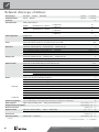
Technical data/scope of delivery

5
SWC 60HS
• ı — ı —
• ı —
•
—
7,2 ı 4,4
—
6,5 ı 3,4
—
7,3 ı 4,6
20 – 65
-5 – 25
—
40
53
1300 ı 1700 ı 2600
— ı —
0,46 ı 1300
•
25 ı -13
600 ı 1200 ı 1500
— ı —
0,42 ı 900
1
200
—
—
G1“AG
G1“AG
R407c ı 1,7
1~/N/PE/230V/50Hz ı C16
1~/N/PE/230V/50Hz ı B10
1~/N/PE/230V/50Hz ı B32
3~/PE/230V/50Hz ı B16A
1,64 ı 8,1 ı 0,88
12,7
— ı 27
20
— ı — ı 6
0,08 ı n.n.
0,1 ı n.n.
—
• ı •
•
•
• ı 12 ı 0,5
• ı 25 ı 1,5
•
• ı •
813178 -d
SWC 80HS
• ı — ı —
• ı —
•
—
9,2 ı 4,5
—
8,4 ı 3,4
—
9,3 ı 4,7
20 – 65
-5 – 25
—
40
53
1700 ı 2200 ı 3300
— ı —
0,64 ı 1700
•
25 ı -13
800 ı 1600 ı 2000
— ı —
0,41 ı 1100
1
203
—
—
G1“AG
G1“AG
R407c ı 1,9
1~/N/PE/230V/50Hz ı C16
1~/N/PE/230V/50Hz ı B10
1~/N/PE/230V/50Hz ı B32
3~/PE/230V/50Hz ı B16A
2,04 ı 10,2 ı 0,87
16,1
— ı 30
20
— ı — ı 6
0,08 ı n.n.
0,2 ı n.n.
—
• ı •
•
•
• ı 12 ı 0,5
• ı 25 ı 1,5
•
• ı •
813179-d
SWC 100HS
• ı — ı —
• ı —
•
—
10,4 ı 4,4
—
9,7 ı 3,5
—
10,5 ı 4,6
20 – 65
-5 – 25
—
40
53
1900 ı 2500 ı 3200
— ı —
0,44 ı 1900
•
25 ı -13
900 ı 1800 ı 2200
— ı —
0,34 ı 1300
1
206
—
—
G1“AG
G1“AG
R407c ı 2,2
1~/N/PE/230V/50Hz ı C20
1~/N/PE/230V/50Hz ı B10
1~/N/PE/230V/50Hz ı B32
3~/PE/230V/50Hz ı B16A
2,36 ı 12,1 ı 0,85
19,1
— ı 31
20
— ı — ı 6
0,08 ı n.n.
0,2 ı n.n.
—
• ı •
•
•
• ı 12 ı 0,5
• ı 25 ı 1,5
•
• ı •
813180- d
Gerätebezeichnung
Heat pump type Brine/water ı Air/water ı Water/water • applicable ı — not applicable
Installation location Indoors ı Outdoors • applicable ı — not applicable
Conformity CE
Performance data Heating capacity/COP at
B0/W35 Standard point acc. to EN14511
2 compresssors
1 compresssor
kW ı …
kW ı …
B0/W45 Standard point acc. to EN14511
2 compresssors
1 compresssor
kW ı …
kW ı …
B0/W35 Standard point acc. to EN255
2 compresssors
1 compresssor
kW ı …
kW ı …
Limits of application Heating circuit °C
Heat source °C
Additional operating points …
Sound Sound level measured at distance of 1m around the device (in free field) dB(A)
Sound power level according to EN12102 dB
Heat source Volume flow: minimum flow rate ı nominal flow rate ı maximum flow rate l/h
Pressure loss heat pump ∆p (with cooling ∆pK) ı volume flow bar (bar) ı l/h
Free compression heat pump ∆p (with cooling ∆pK) ı volume flow bar (bar) ı l/h
Anti-freeze agent monoethylene glycol
minimum concentration ı frost proof down to % ı °C
Heating circuit Volume flow: minimum flow rate ı nominal flow rate ı maximum flow rate l/h
Pressure loss heat pump ∆p (with cooling ∆pK) ı volume flow bar (bar) ı l/h
Free compression heat pump ∆p (with cooling ∆pK) ı volume flow bar (bar) ı l/h
General unit data Dimensions (see dimensional drawing for the specified unit size) unit size
Total weight (including cooling) kg (kg)
Additional weight module 1 kg
Additional weight module 2 kg
Connections Heating circuit …
Heat source …
Refrigerant Refrigerant type ı Quantity … ı kg
Electric Voltage code ı all-pole circuit breaker heat pump *) … ı A
Voltage code ı circuit breaker control voltage *) … ı A
Voltage code ı circuit breaker electric heating element 1~230V*) ı A
Voltage code ı circuit breaker electric heating element 3~230V*)
Heat Pump
Effective power consumption in standard point B0/W35 according to EN14511: Power consumption ı current consumption ı cosφ kW ı A ı …
Maximum device current within the limits of application A
Starting current: direct ı with soft starter A ı A
Protection type IP
Output electric heating element 3 ı 2 ı 1 phase kW ı kW ı kW
Components Circulating pump heating circuit at nominal flow rate: Power consumption ı current consumption kW ı A
Circulating pump heat source at nominal flow rate: Power consumption ı current consumption kW ı A
Passive cooling function only for units with designator K: Cooling output at nominal volume ow (15 °C heat source, 25 °C heating water) kW
Safety equipment Safety component heating circuit ı Safety component heat source scope of delivery: • yes — no
Heating and heat pump regulator scope of delivery: • yes — no
Electronic soft starter integrated: • yes — no
Expansion vessels Heat source: Scope of delivery ı Volume ı Initial pressure • yes — no ı l ı bar
Heating circuit: Scope of delivery ı Volume ı Initial pressure • yes — no ı l ı bar
Overflow valve integrated: • yes — no
Vibration decouplers Heating circuit ı heat source scope of delivery: • yes — no
UK813196-c
*) comply with local regulations n.n. = not detectable
We reserve the right to modify technical specifications without prior notice.
83060000eUK © ait-deutschland GmbH

6
Gerätebezeichnung
Heat pump type Brine/water ı Air/water ı Water/water • applicable ı — not applicable
Installation location Indoors ı Outdoors • applicable ı — not applicable
Conformity CE
Performance data Heating capacity/COP at
B0/W35 Standard point acc. to EN14511
2 compresssors
1 compresssor
kW ı …
kW ı …
B0/W45 Standard point acc. to EN14511
2 compresssors
1 compresssor
kW ı …
kW ı …
B0/W35 Standard point acc. to EN255
2 compresssors
1 compresssor
kW ı …
kW ı …
Limits of application Heating circuit °C
Heat source °C
Additional operating points …
Sound Sound level measured at distance of 1m around the device (in free field) dB(A)
Sound power level according to EN12102 dB
Heat source Volume flow: minimum flow rate ı nominal flow rate ı maximum flow rate l/h
Pressure loss heat pump ∆p (with cooling ∆pK) ı volume flow bar (bar) ı l/h
Free compression heat pump ∆p (with cooling ∆pK) ı volume flow bar (bar) ı l/h
Anti-freeze agent monoethylene glycol
minimum concentration ı frost proof down to % ı °C
Heating circuit Volume flow: minimum flow rate ı nominal flow rate ı maximum flow rate l/h
Pressure loss heat pump ∆p (with cooling ∆pK) ı volume flow bar (bar) ı l/h
Free compression heat pump ∆p (with cooling ∆pK) ı volume flow bar (bar) ı l/h
General unit data Dimensions (see dimensional drawing for the specified unit size) unit size
Total weight (including cooling) kg (kg)
Additional weight module 1 kg
Additional weight module 2 kg
Connections Heating circuit …
Heat source …
Refrigerant Refrigerant type ı Quantity … ı kg
Electric Voltage code ı all-pole circuit breaker heat pump *) … ı A
Voltage code ı circuit breaker control voltage *) … ı A
Voltage code ı circuit breaker electric heating element 1~230V*) ı A
Voltage code ı circuit breaker electric heating element 3~230V*)
Heat Pump
Effective power consumption in standard point B0/W35 according to EN14511: Power consumption ı current consumption ı cosφ kW ı A ı …
Maximum device current within the limits of application A
Starting current: direct ı with soft starter A ı A
Protection type IP
Output electric heating element 3 ı 2 ı 1 phase kW ı kW ı kW
Components Circulating pump heating circuit at nominal flow rate: Power consumption ı current consumption kW ı A
Circulating pump heat source at nominal flow rate: Power consumption ı current consumption kW ı A
Passive cooling function only for units with designator K: Cooling output at nominal volume ow (15 °C heat source, 25 °C heating water) kW
Safety equipment Safety component heating circuit ı Safety component heat source scope of delivery: • yes — no
Heating and heat pump regulator scope of delivery: • yes — no
Electronic soft starter integrated: • yes — no
Expansion vessels Heat source: Scope of delivery ı Volume ı Initial pressure • yes — no ı l ı bar
Heating circuit: Scope of delivery ı Volume ı Initial pressure • yes — no ı l ı bar
Overflow valve integrated: • yes — no
Vibration decouplers Heating circuit ı heat source scope of delivery: • yes — no
UK813196-c
*) comply with local regulations n.n. = not detectable
We reserve the right to modify technical specifications without prior notice.
83060000eUK © ait-deutschland GmbH
Technical data/scope of delivery

7
Gerätebezeichnung
Heat pump type Brine/water ı Air/water ı Water/water • applicable ı — not applicable
Installation location Indoors ı Outdoors • applicable ı — not applicable
Conformity CE
Performance data Heating capacity/COP at
B0/W35 Standard point acc. to EN14511
2 compresssors
1 compresssor
kW ı …
kW ı …
B0/W45 Standard point acc. to EN14511
2 compresssors
1 compresssor
kW ı …
kW ı …
B0/W35 Standard point acc. to EN255
2 compresssors
1 compresssor
kW ı …
kW ı …
Limits of application Heating circuit °C
Heat source °C
Additional operating points …
Sound Sound level measured at distance of 1m around the device (in free field) dB(A)
Sound power level according to EN12102 dB
Heat source Volume flow: minimum flow rate ı nominal flow rate ı maximum flow rate l/h
Pressure loss heat pump ∆p (with cooling ∆pK) ı volume flow bar (bar) ı l/h
Free compression heat pump ∆p (with cooling ∆pK) ı volume flow bar (bar) ı l/h
Anti-freeze agent monoethylene glycol
minimum concentration ı frost proof down to % ı °C
Heating circuit Volume flow: minimum flow rate ı nominal flow rate ı maximum flow rate l/h
Pressure loss heat pump ∆p (with cooling ∆pK) ı volume flow bar (bar) ı l/h
Free compression heat pump ∆p (with cooling ∆pK) ı volume flow bar (bar) ı l/h
General unit data Dimensions (see dimensional drawing for the specified unit size) unit size
Total weight (including cooling) kg (kg)
Additional weight module 1 kg
Additional weight module 2 kg
Connections Heating circuit …
Heat source …
Refrigerant Refrigerant type ı Quantity … ı kg
Electric Voltage code ı all-pole circuit breaker heat pump *) … ı A
Voltage code ı circuit breaker control voltage *) … ı A
Voltage code ı circuit breaker electric heating element 1~230V*) ı A
Voltage code ı circuit breaker electric heating element 3~230V*)
Heat Pump
Effective power consumption in standard point B0/W35 according to EN14511: Power consumption ı current consumption ı cosφ kW ı A ı …
Maximum device current within the limits of application A
Starting current: direct ı with soft starter A ı A
Protection type IP
Output electric heating element 3 ı 2 ı 1 phase kW ı kW ı kW
Components Circulating pump heating circuit at nominal flow rate: Power consumption ı current consumption kW ı A
Circulating pump heat source at nominal flow rate: Power consumption ı current consumption kW ı A
Passive cooling function only for units with designator K: Cooling output at nominal volume ow (15 °C heat source, 25 °C heating water) kW
Safety equipment Safety component heating circuit ı Safety component heat source scope of delivery: • yes — no
Heating and heat pump regulator scope of delivery: • yes — no
Electronic soft starter integrated: • yes — no
Expansion vessels Heat source: Scope of delivery ı Volume ı Initial pressure • yes — no ı l ı bar
Heating circuit: Scope of delivery ı Volume ı Initial pressure • yes — no ı l ı bar
Overflow valve integrated: • yes — no
Vibration decouplers Heating circuit ı heat source scope of delivery: • yes — no
UK813196-c
*) comply with local regulations n.n. = not detectable
SWC 170HP(/K)
• ı — ı —
• ı —
•
—
16,7 ı 4,6
—
—
16,9 ı 4,7
20 – 65
-5 – 25
—
43
56
2700 ı 3600 ı 5000
— ı —
1,0 (0,97) ı 2700
•
25 ı -13
1400 ı 2900 ı 3500
— ı —
0,58 (0,55) ı 2050
1
220 (235)
—
—
G1¼»AG
G1¼»AG
R407c ı 3,8
3~/PE/400V/50Hz ı C13
1~/N/PE/230V/50Hz ı B10
3~/N/PE/400V/50Hz ı C16
3,63 ı 6,7 ı 0,78
11,0
— ı 30
20
9 ı 6 ı 3
0,2 ı n.n.
0,25 ı n.n.
9,0
• ı •
•
•
• ı 18 ı 0,5
• ı 35 ı 1,5
•
• ı •
813197-b
SWC 140S
• ı — ı —
• ı —
•
—
14,5 ı 4,4
—
13,9 ı 3,4
—
14,7 ı 4,6
20 – 55
-5 – 25
—
45
58
2600 ı 3500 ı 4300
— ı —
0,36 ı 3500
•
25 ı -13
1200 ı 2500 ı 3100
— ı —
0,6 ı 2500
1
212
—
—
G1¼“AG
G1¼“AG
R407c ı 2,7
1~/N/PE/230V/50Hz ı C32
1~/N/PE/230V/50Hz ı B10
1~/N/PE/230V/50Hz ı C40
3~/PE/230V/50Hz ı B25A
3,29 ı 15,0 ı 0,95
26,3
— ı 45
20
— ı — ı 9
0,2 ı n.n.
0,25 ı n.n.
—
• ı •
•
•
• ı 18 ı 0,5
• ı 35 ı 1,5
•
• ı •
813182-g
SWC 120S
• ı — ı —
• ı —
•
—
11,7 ı 4,6
—
11,2 ı 3,5
—
11,9 ı 4,8
20 – 55
-5 – 25
—
45
58
2100 ı 2800 ı 4300
— ı —
0,6 ı 2800
•
25 ı -13
1000 ı 2000 ı 2500
— ı —
0,26 ı 2000
1
209
—
—
G1¼“AG
G1¼“AG
R407c ı 2,4
1~/N/PE/230V/50Hz ı C25
1~/N/PE/230V/50Hz ı B10
1~/N/PE/230V/50Hz ı B32
3~/PE/230V/50Hz ı B16A
2,54 ı 13,0 ı 0,85
22,0
— ı 33
20
— ı — ı 6
0,09 ı n.n.
0,2 ı n.n.
—
• ı •
•
•
• ı 18 ı 0,5
• ı 25 ı 1,5
•
• ı •
813181-g
We reserve the right to modify technical specifications without prior notice.
83060000eUK © ait-deutschland GmbH

8
823008
Legende: DE823000LS
“” Volumenstrom Heizwasser
“„ Volumenstrom Wärmequelle
Temp„ Temperatur Wärmequelle
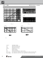
Qh Heizleistung
Pe Leistungsaufnahme
COP Coeffiicient of performance / Leistungszahl
∆p” Freie Pressung Heizkreis
∆p„ Freie Pressung Wärmequelle
Änd./Ä.M./Ersteller/Datum
Bezeichnung:
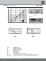
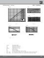
Leistungs-Druckverlustkurven
- / ÄM001-2007 / Neumann / 04.04.07
Seite: 1/1
SWC 60HS
Zeichnungsnummer: 823008
Datei: 823008 Leistungs-Druckverlustkurven SWC60HS.xls
Qh (kW)
4
6
8
10
12
14
-10 -5 0 5 10 15 20 25 30
Temp„ (°C)
35°C
50°C
65°C
COP
1
2
3
4
5
6
7
8
-10 -5 0 5 10 15 20 25 30
Temp„ (°C)
Pe (kW)
0
1
2
3
4
-10 -5 0 5 10 15 20 25 30
Temp„ (°C)
∆p (bar)
0,0
0,1
0,2
0,3
0,4
0,5
0,6
0,7
0,8
0,0 0,5 1,0 1,5 2,0 2,5 3,0 3,5
“”[m3/h]
∆p”
∆p (bar)
0,0
0,1
0,2
0,3
0,4
0,5
0,6
0,7
0,8
0,0 0,5 1,0 1,5 2,0 2,5 3,0 3,5
“„[m3/h]
∆p„
Legend: UK823000L/170408
“” Volume ow, heating water
“„ Volume ow, heat source
Temp„ Temperature, heat source
Qh Heating capacity
Pe Power consumption
COP Coefcient of performance / efciency rating
∆p” / ∆p”† Free compression, heating circuit / free compression, heating circuit with cooling
∆p„ / ∆p„† Free compression, heat source / free compression, heat source with cooling
We reserve the right to modify technical specifications without prior notice.
83060000eUK © ait-deutschland GmbH
Performance curvesSWC 60HS

9
Legende: DE823000LS
823009
“” Volumenstrom Heizwasser
Volumenstrom Wärmequelle
Temperatur Wärmequelle
Heizleistung
“„
Temp„
Qh
Pe
COP
Leistungsaufnahme
Coeffiicient of performance / Leistungszahl
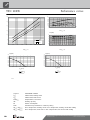
Qh (kW)
6
8
10
12
14
16
-10 -5 0 5 10 15 20 25 30
Temp„ (°C)
35°C
50°C
65°C
COP
1
2
3
4
5
6
7
8
-10 -5 0 5 10 15 20 25 30
Temp„ (°C)
Pe (kW)
0
1
2
3
4
5
-10 -5 0 5 10 15 20 25 30
Temp„ (°C)
∆p (bar)
0,0
0,1
0,2
0,3
0,4
0,5
0,6
0,7
0,8
0,0 0,5 1,0 1,5 2,0 2,5 3,0 3,5
“”[m3/h]
∆p”
∆p (bar)
0,0
0,1
0,2
0,3
0,4
0,5
0,6
0,7
0,8
0,9
1,0
0,0 0,5 1,0 1,5 2,0 2,5 3,0 3,5 4,0 4,5 5,0
“„[m3/h]
∆p„
Legend: UK823000L/170408
“” Volume ow, heating water
“„ Volume ow, heat source
Temp„ Temperature, heat source
Qh Heating capacity
Pe Power consumption
COP Coefcient of performance / efciency rating
∆p” / ∆p”† Free compression, heating circuit / free compression, heating circuit with cooling
∆p„ / ∆p„† Free compression, heat source / free compression, heat source with cooling
We reserve the right to modify technical specifications without prior notice.
83060000eUK © ait-deutschland GmbH
Performance curves SWC 80HS

10
“„
Temp„
Qh
Pe
COP
Leistungsaufnahme
Coeffiicient of performance / Leistungszahl
Volumenstrom Heizwasser
Volumenstrom Wärmequelle
Temperatur Wärmequelle
Heizleistung
Legende: DE823000LS
823010
“”
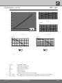
Qh (kW)
6
8
10
12
14
16
18
-10 -5 0 5 10 15 20 25 30
Temp„ (°C)
35°C
50°C
65°C
COP
1
2
3
4
5
6
7
8
-10 -5 0 5 10 15 20 25 30
Temp„ (°C)
Pe (kW)
0
1
2
3
4
5
-10 -5 0 5 10 15 20 25 30
Temp„ (°C)
∆p (bar)
0,0
0,1
0,2
0,3
0,4
0,5
0,6
0,7
0,8
0,0 0,5 1,0 1,5 2,0 2,5 3,0 3,5
“”[m3/h]
∆p”
∆p (bar)
0,0
0,1
0,2
0,3
0,4
0,5
0,6
0,7
0,8
0,9
1,0
0,0 0,5 1,0 1,5 2,0 2,5 3,0 3,5 4,0 4,5 5,0
“„[m3/h]
∆p„
Legend: UK823000L/170408
“” Volume ow, heating water
“„ Volume ow, heat source
Temp„ Temperature, heat source
Qh Heating capacity
Pe Power consumption
COP Coefcient of performance / efciency rating
∆p” / ∆p”† Free compression, heating circuit / free compression, heating circuit with cooling
∆p„ / ∆p„† Free compression, heat source / free compression, heat source with cooling
We reserve the right to modify technical specifications without prior notice.
83060000eUK © ait-deutschland GmbH
Performance curvesSWC 100HS

11
Bezeichnung:
Seite: 1/1
Pe
COP
Legende: DE823024LS
823011a
Leistungsaufnahme
Coeffiicient of performance / Leistungszahl
Temperatur Wärmequelle
Heizleistung
“„
Temp„
“”
Freie Pressung Heizkreis
Volumenstrom Heizwasser
Volumenstrom Wärmequelle
∆p”
∆p„ Freie Pressung Wärmequelle
Qh
Datei: 823011a Leistungs-Druckverlustkurven SWC120S.xls
Leistungs-Druckverlustkurven
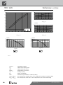
SWC 120S
Zeichnungsnummer: 823011a
Änd./Ä.M./Ersteller/Datum
- / ÄM001-2007 / Neumann / 04.04.07
a / ÄM041-2014 / Hohenberger / 17.06.15
8
10
12
14
16
18
20
22
-10 -5 0 5 10 15 20 25 30
Temp„ (°C)
Qh (kW)
35°C
50°C
1
2
3
4
5
6
7
8
-10 -5 0 5 10 15 20 25 30
Temp„ (°C)
COP
2
3
4
5
-10 -5 0 5 10 15 20 25 30
Temp„ (°C)
Pe (kW)
0,0
0,1
0,2
0,3
0,4
0,5
0,6
0,7
0,8
0,0 0,5 1,0 1,5 2,0 2,5 3,0 3,5
“”[m3/h]
∆p (bar)
Δ
p”
Pol
…
0,0
0,1
0,2
0,3
0,4
0,5
0,6
0,7
0,8
0,9
1,0
0,0 0,5 1,0 1,5 2,0 2,5 3,0 3,5 4,0 4,5 5,0
“„[m3/h]
∆p (bar)
Δp„
Pol
…
Legend: UK823000L/170408
“” Volume ow, heating water
“„ Volume ow, heat source
Temp„ Temperature, heat source
Qh Heating capacity
Pe Power consumption
COP Coefcient of performance / efciency rating
∆p” / ∆p”† Free compression, heating circuit / free compression, heating circuit with cooling
∆p„ / ∆p„† Free compression, heat source / free compression, heat source with cooling
We reserve the right to modify technical specifications without prior notice.
83060000eUK © ait-deutschland GmbH
Performance curves SWC 120S

12
Bezeichnung:
Seite: 1/1
Datei: 823012a Leistungs-Druckverlustkurven SWC140S.xls
Leistungs-Druckverlustkurven
SWC 140S
Zeichnungsnummer: 823012a
Legende: DE823024LS
823012a
∆p„
“”
Freie Pressung Heizkreis
Volumenstrom Heizwasser
Volumenstrom Wärmequelle
Temperatur Wärmequelle
Heizleistung
Leistungsaufnahme
Coeffiicient of performance / Leistungszahl
a / ÄM041-2014 / Hohenberger / 17.06.15
Änd./Ä.M./Ersteller/Datum
- / ÄM001-2007 / Neumann / 04.04.07
Freie Pressung Wärmequelle
“„
Temp„
Qh
Pe
COP
∆p”
10
12
14
16
18
20
22
24
-10 -5 0 5 10 15 20 25 30
Temp„ (°C)
Qh (kW)
35°C
50°C
1
2
3
4
5
6
7
8
-10 -5 0 5 10 15 20 25 30
Temp„ (°C)
COP
2
3
4
5
6
-10 -5 0 5 10 15 20 25 30
Temp„ (°C)
Pe (kW)
0,0
0,1
0,2
0,3
0,4
0,5
0,6
0,7
0,8
0,9
1,0
0,0 0,5 1,0 1,5 2,0 2,5 3,0 3,5 4,0
“”[m3/h]
∆p (bar)
Δ
p”
Pol
…
0,0
0,1
0,2
0,3
0,4
0,5
0,6
0,7
0,8
0,9
1,0
0,0 0,5 1,0 1,5 2,0 2,5 3,0 3,5 4,0 4,5 5,0
“„[m3/h]
∆p (bar)
Δp„
Pol
…
Legend: UK823000L/170408
“” Volume ow, heating water
“„ Volume ow, heat source
Temp„ Temperature, heat source
Qh Heating capacity
Pe Power consumption
COP Coefcient of performance / efciency rating
∆p” / ∆p”† Free compression, heating circuit / free compression, heating circuit with cooling
∆p„ / ∆p„† Free compression, heat source / free compression, heat source with cooling
We reserve the right to modify technical specifications without prior notice.
83060000eUK © ait-deutschland GmbH
Performance curvesSWC 140S

13
Bezeichnung:
Seite: 1/1
Datei: 823020
Leistungs-Druckverlustkurven
SWC 170HP (/K)
Zeichnungsnummer: 823020
Änd./Ä.M./Ersteller/Datum
- / PEP011-2007 / Neumann / 10.04.07
Legende: DE823000L
823020
“”
Freie Pressung Heizkreis / Freie Pressung Heizkreis mit Kühlung
Volumenstrom Heizwasser
Volumenstrom Wärmequelle
Temperatur Wärmequelle
Heizleistung
Freie Pressung Wärmequelle / Freie Pressung Wärmequelle mit Kühlung
“„
Temp„
Qh
Pe
COP
p” / p”†
p„ / p„†
Leistungsaufnahme
Coeffiicient of performance / Leistungszahl
Qh (kW)
12
14
16
18
20
22
24
26
28
30
-10 -5 0 5 10 15 20 25 30
Temp„ (°C)
35°C
50°C
65°C
COP
1
2
3
4
5
6
7
8
-10 -5 0 5 10 15 20 25 30
Temp„ (°C)
Pe (kW)
2
3
4
5
6
7
8
-10 -5 0 5 10 15 20 25 30
Temp„ (°C)
p (bar)
0,0
0,1
0,2
0,3
0,4
0,5
0,6
0,7
0,8
0,9
1,0
0,0 0,5 1,0 1,5 2,0 2,5 3,0 3,5 4,0 4,5 5,0
“”
p” p”†
p (bar)
0,0
0,1
0,2
0,3
0,4
0,5
0,6
0,7
0,8
0,9
1,0
1,1
1,2
1,3
1,4
0,0 0,5 1,0 1,5 2,0 2,5 3,0 3,5 4,0 4,5 5,0 5,5 6,0 6,5 7,0
“„
p„ p„†
Legend: UK823000L/170408
“” Volume ow, heating water
“„ Volume ow, heat source
Temp„ Temperature, heat source
Qh Heating capacity
Pe Power consumption
COP Coefcient of performance / efciency rating
∆p” / ∆p”† Free compression, heating circuit / free compression, heating circuit with cooling
∆p„ / ∆p„† Free compression, heat source / free compression, heat source with cooling
We reserve the right to modify technical specifications without prior notice.
83060000eUK © ait-deutschland GmbH
Performance curves
SWC 170HP(K)

14
-F11 -F12 -F13
A1
A2
P
circulation pump
1L2
ZW1
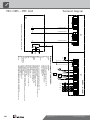
Information on fuses can be found in the technical data
1N3
3
ZW1
ZIP
ZW2/SST
1N1
230V 1~, 6 - 14 kW
A3
ZUP
X10:L1,N,PE
Power supply compressor 230VX10:L1,N,PE
Auxiliary heating 230V
Control signal of additional heat generator 2 (alternative is general malfunction)
Brine water compact 6 - 14 kW, 230V 1~
X10
Control 230V
F12
PE
X10:1L1,1N1,PE
Terminal strip in switchbox of heat pump; N/PE distribution for external 230V units
VBO
TBW
-X3
ZW2/SST
Terminals
Auxiliary circulation pump
GND
1~N/PE/230V/50Hz
Accessories: Process water sensor/thermostat
MOT
A2
-X0
Pump for mixing circuit 1
Brine circulation pump
MA1
Terminal strips on controller board (see sticker)
Control signal of additional heat generator 1; internally wired
A1
1L3
ZW2/SST
A1
L1
VBO
FP1
TBW
X0-X4
Accessories: Process water for changeover valve
2
Cut out compressor
PE
EVU
-X2
F13
ASD
TBW
GND
L1
HUP
PE
N
A3
Sub-distribution unit internal installation
Name
ZUP
L1
BUP
Heating circuit circulation pump; internally wired
TA
N
BUP
N
Charge/discharge/cooling mixer 1 closed
GND
EVU
N
TB1
Legend:
ASD
M
HUP
External sensor
Overload protection; internally wired
MZ1
-X4
no function
TB1
MZ1/MIS
L1
L
-X10
3
ZIP
TRL
MOT
M
MA1/MIS
1L1
3
Charge/discharge/cooling mixer 1 open
TB1
1~N/PE/230V/50Hz
TA
External return sensor
PEX
ZIP
PE
PE
PE
1~N/PE/230V/50Hz
Brine pressure pressostat; provided by cust. if necessary
GND
Energy supplier contact; closed on release; bridge if no blocking interval
BUP
N
Controller board; Attention: I-max = 6A/230VAC
Function
EVU
A2
PEX
Cut out controller unit
FP1
GND
RFV
M
F11
Sensor mixing circuit 1
MIS
Terminals in heat pump switchbox
PE
ASD
TRL
TA
GND
FP1
N
UK831145a
Accessories: Remote control
ZW1
Cut out auxiliary heating
RFV
1N2
RFV
terminal diagram SWC 60-140S LUX2
831145
Achim Pfleger
1 x 230V
28.08.2008
a ÄM 045/2013
1 2 3 4 5 6 7 8 9 10 11 12 13 14 15 16
1 2 3 4 5 6 7 8 9 10 11 12 13 14 15 16
1/1
1
25.07.2013
-
Achim Pfleger
Blatt-Nr.
Zustand
Änderung
Bearb.
Datum
Name
Bl von Anz
Datum
We reserve the right to modify technical specifications without prior notice.
83060000eUK © ait-deutschland GmbH
Terminal diagramSWC 60HS – SWC 140S

15
-F12 -F10 -F11
L Y2
A1
A2
4
1
5
2
P
FP1
PE
PE
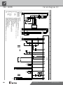
With cooling option: Room thermostat; bridge if not connected
A2
RFV
M
N
PEX
4
Y3
Function
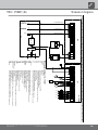
Legend:
VBO
ZW1
ZUP
RFV
GND
3-pol. Cut out compressor; Attention: Right-hand rot. field is mandatory!
BUP
Terminals in heat pump switchbox
Cut out controller unit
Accessories: Transformer for dewpoint monitor
Controller board; Attention: I-max = 6A/230VAC
PE
ZW1
Accessories with cooling option: Dewpoint monitor; bridge if not connected
Brine pressure pressostat; provided by cust. if necessary
1~N/PE/230V/50Hz
GND
L1
PE
RFV
FP1
GND
L2
N
L1
UK831138
Energy supplier contact; closed on release; bridge if no blocking interval
F10
B10 A
230V
-T2
Auxiliary circulation pump
2
Brine water compact 6 - 17 kW
3~N/PE/400V/50Hz
X7:PE,N,L1
ZIP
2
-Y3
X7:PE,N,L1,L2,L3
EVU
6 - 17 kW
-X2
N
TBW
Auxiliary heating 3 x 400V
X7
2
Terminal strip in switchbox of heat pump; N/PE distribution for external 230V units
Brine circulation pump
1
Power supply compressor 3 x 400V; Attention: Right-hand rot. field is mandatory!
Y2
Terminals
M
A2
VBO
Control signal of additional heat generator 2 (alternative is general malfunction)
-X0
Control signal of additional heat generator 1; internally wired
X7:PE,L1,L2,L3
Terminal strips on controller board
Control 230V
L3
-Y2
24V
3
T2
F11
ZW2/SST
MA1
-X3
HUP
BUP
BUP
TBW
L1
ZW1
TA
GND
FP1
N
ZW2/SST
ZIP
6-12 kW: C10 A
14-17 kW: C16 A14-17 kW: C16 A
circulation pump
M
ZIP
L2
Sub-distribution unit internal installation
Cut out auxiliary heating
Heating circuit circulation pump; internally wired
L1
PE
A1
PE
F12
2
N
TBW
Name
ZUP
L1
Accessories: Process water for changeover valve
L3
A3
5
MOT
PE
N
A3
A1
ZW2/SST
X0-X4
TB1
Accessories: Process water sensor/thermostat
GND
TRL
TB1
-X7
TA
HUP
L1
EVU
GND
TRL
ASD
MA1/MIS
External sensor
MZ1
N
Pump for mixing circuit 1
N
EVU
ASD
Overload protection; internally wired
Charge/discharge/cooling mixer 1 open
PEX
Charge/discharge/cooling mixer 1 closed
Accessories: Remote control
-X4
PE
ASD
3~PE/400V/50Hz
MOT
2
2
Sensor mixing circuit 1
MZ1/MIS
no function
3
6-12 kW: C10 A
14-17 kW: C16 A14-17 kW: C16 A
MIS
PE
TB1
External return sensor
TA
08.12.2006Achim Pfleger
1/1
SWC 60-170 terminal diagram
1 2 3 4 5 6 7 8 9 10 11 12 13 14 15
16
1
02.04.2009
1 2 3 4 5 6 7 8 9 10 11 12 13 14 15 16
Georg Bächmann
ÄM
Zustand
Index:
Bl von AnzÄnderung
Urspr.
Blatt-Nr.
Bearb.
Datum
Name
Norm
Ers. für
Projekt:
Gepr.
ANr.
Ers. durch
Datum
We reserve the right to modify technical specifications without prior notice.
83060000eUK © ait-deutschland GmbH
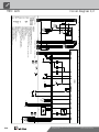
Terminal diagramSWC 170HP(/K)

16
L1
-X10
N PE
1
2
-Q1
8
123
14
2
4
-Q11
3
4
1
35
246
-F4
M
3
T1
T2
T3
PE
-M1
VD1
5
6
-C1
1L1
-X10
1L2
1L3
1
2
-Q5
14
1N1
-X10
3
4
1N2
5
6
1N3
PE
L
-X0
L
-X10
N
N
PE
PE
N..
-X1
P
+-
b2 c4
a1
-F1
HDP
HD.
12
2
34
2
56
2
13 14
VD1
-X1
A1
A2
-Q1
VD1
ND.
-X1
P
-+
c4 b2
a1
-F2
NDP
L..
L
-X0
95
96
-F4
2
L L
MOT
-X2
EVU
-X2
HUP
-X3
M
1
L N PE
-M4
BUP
-X3
12
-K23
VBO
-X3
M
1
L N PE
-M3
12
5
34
5
56
5
13 14
ZW1
-X3
ϑ
-STB
A1
A2
-Q5
ZW1
MA1
-X3
MZ1
M
1
A
Z
N
PE
-M16
MIS
9596
10
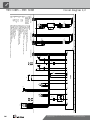
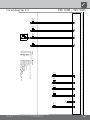
High-pressure switch
Energy supplier contact; closed on release; bridge if no blocking interval
Overload relay for compressor 1
F2
HDP
b
l
2
3
NDP Low-pressure switch
-K10
EVU
2
Legend:
1~N/PE/230V/50Hz
230VAC
F4
F1
b
r bl
L1/N/PE: Power supply output compressor
gr
Heating circulation pump
bl
K10
M3
Mixer; installed with cooling option
bl
M1
rt
Compressor 1
BOSUP
M16
VD1
1
BUP
EVU
C1
K23
Starting current limit compressor 1
1~N/PE/230V/50Hz
Operating condenser compressor 1
Function
bl
1
Terminal strip in switchbox of heat pump; N/PE distribution for external 230V units
1~N/PE/230V/50Hz
M4
-E22
Operating materials
E22
Accessories: Process water for changeover valve
X10
2
Contactor for auxiliary heating
Brine pump
HUP
ZW1Q5
VD1
MIS
Contactor for compressor 1
Auxiliary heating
Q1
Q11
ZW1
1~N/PE/230V/50Hz
1~N/PE/230V/50Hz
1
1L1/1L2/1L3/1N1/1N2/1N3/PE: power supply, additional heating
2
bl
1~N/PE/230V/50Hz
Controller board; Attention: I-max = 6A/230VAC
1
UK817259f
L/N/PE: Control supply
46 2
Safety temperature limiter heating element
STB
bl
bl
5
13
SWC 60-80S
817259
Achim Pfleger
1 x 230V
17.05.1999
f ÄM 045/2013
1 2 3 4 5 6 7 8 9 10 11 12 13 14 15
16
1 2 3 4 5 6 7 8 9 10 11 12 13 14 15 16
1/2
1
25.07.2013
ÄM 036/2007e
Escher F.
Blatt-Nr.
Zustand
Änderung
Bearb.
Datum
Name
Bl von Anz
Datum
We reserve the right to modify technical specifications without prior notice.
83060000eUK © ait-deutschland GmbH
Circuit diagram 1/2SWC 60HS – SWC 80HS

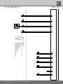
17
ϑ
RFV
-X4
-R10
RFV
GND
ϑ
TB1
-X4
-R13
TB1
GND
TR
ϑ
TBW
-X4
-R9
TBW
GND
ϑ
TA.
-X4
-R8
TA
GND
ϑ
TRL
-X5
-R4
TRL
GND
ϑ
TVL
-X5
-R5
TVL
GND
ϑ
THG
-X5
-R6
THG
GND
ϑ
TWA
-X5
-R11
TWA
GND
CW.
-X5
-R12
GND
ϑ
TWE
-X5
-R7
TWE
GND
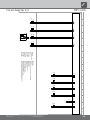
Heat source input sensor
-K10
-Y4
BWT
-CW
R8 External sensor
Y4
Heat pump coding; SWC - 845 ohmCW
Function
Hot gas sensor
TVL
TB1
RFV
Return sensor
Accessories: Process water for thermostatBWT
R10
Controller board; Attention: I-max = 6A/230VAC
Sensor mixing circuit 1; installed with cooling option
TRL
R7
Heat source output sensor
R6
R9
Operating materials
Legend:
TA
K10
Accessories: Remote control
R4
TWA
Flow sensor
R12
Domestic hot water sensor
R13
R11
TWE
THG
UK817259f
R5
TBW
SWC 60-80S
Achim Pfleger
1 x 230V
17.05.1999
f ÄM 045/2013
1 2 3 4 5 6 7 8 9 10 11 12 13 14 15 16
1 2 3 4 5 6 7 8 9 10 11 12 13 14 15 16
2/2
2
25.07.2013
ÄM 036/2007e
Escher F.
Blatt-Nr.
Zustand
Änderung
Bearb.
Datum
Name
Bl von Anz
Datum
We reserve the right to modify technical specifications without prior notice.
83060000eUK © ait-deutschland GmbH
Circuit diagram 2/2 SWC 60HS – SWC 80HS

18
L1 N PE
1
2
-Q1
8
-F6
3
4
1
35
246
-F4
5
6
M
1
C
S
R
PE
-M1
-C1
14
11
-K6
9
R
RC
L1
S
ON
N
-Q11
1L1
-X10
1L1
1L1
1
2
-Q5
15
1N1
-X10
3
4
1N2
5
6
1N3
PE
L
-X0
L
-X10
N
N
PE
PE
N..
-X1
P
+-
b2 c4
a1
-F1
HDP
HD.
A1
A2
-Q1
VD1
12
2
34
2
56
2
13 14
VD1
-X1
A1
A2
-K6
ND.
-X1
P
-+
c4 b2
a1
-F2
NDP
L..
L
-X0
95
96
-F4
2
L L
MOT
-X2
EVU
-X2
HUP
-X3
M
1
L N PE
-M4
BUP
-X3
12
-Y1
VBO
-X3
M
1
L N PE
-M3
12
5
34
6
56
6
13 14
ZW1
-X3
ϑ
-STB
A1
A2
-Q5
ZW1
MA1
-X3
MZ1
M
1
A
Z
N
PE
-M16
MIS
14 11
4
9596
11
High-pressure switch
b
l
F2
b
r
Energy supplier contact; closed on release; bridge if no blocking interval
Low-pressure switch
3
EVU
2
gr
1
1~N/PE/230V/50Hz
F4
bl
1~N/PE/230V/50Hz
bl
1~N/PE/230V/50Hz
Overload relay for compressor 1
HDPF1
-K10
NDP
C1
Safety temperature limiter heating element
1
Operating materials
Starting current limit compressor 1
ZW1
3
5
starting current safety delimiter
46 2
Contactor for auxiliary heating
STB
1
Function
Operating condenser compressor 1
BOSUP
E22
Compressor 1
bl
bl
M1
L1/N/PE: Power supply output compressor
M4
1
2
Accessories: Process water for changeover valve
Terminal strip in switchbox of heat pump; N/PE distribution for external 230V units
X10
Contactor for compressor 1
ZW1
Brine pump
Q5
VD1
HUP
Auxiliary heating
MIS
Q1
Q11
K10
Mixer; installed with cooling option
Heating circulation pump
M3
K23
1~N/PE/230V/50Hz
M16
bl
BUP
L/N/PE: Control supply
UK817342a
bl
1~N/PE/230V/50Hz
230VAC
bl
-E22
VD1
1~N/PE/230V/50Hz
F6
Controller board; Attention: I-max = 6A/230VAC
auxiliary relay compressor 1
rt
K6
1L1/1L2/1L3/1N1/1N2/1N3/PE: power supply, additional heating
2
1
Legend:
EVU
2
SWC 100 H/S
817342
Achim Pfleger 28.04.2009
a ÄM 045/2013
1 2 3 4 5 6 7 8 9 10 11 12 13 14 15
16
1 2 3 4 5 6 7 8 9 10 11 12 13 14 15 16
1/2
1
25.07.2013
PEP 017/2008-
Achim Pfleger
10X452
Blatt-Nr.
Zustand
Änderung
Bearb.
Datum
Name
Bl von Anz
Datum
We reserve the right to modify technical specifications without prior notice.
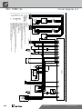
83060000eUK © ait-deutschland GmbH
Circuit diagram 1/2SWC 100HS

19
ϑ
RFV
-X4
-R10
RFV
GND
ϑ
TB1
-X4
-R13
TB1
GND
TR
ϑ
TBW
-X4
-R9
TBW
GND
ϑ
TA.
-X4
-R8
TA
GND
ϑ
TRL
-X5
-R4
TRL
GND
ϑ
TVL
-X5
-R5
TVL
GND
ϑ
THG
-X5
-R6
THG
GND
ϑ
TWA
-X5
-R11
TWA
GND
CW.
-X5
-R12
GND
ϑ
TWE
-X5
-R7
TWE
GND
K10
Accessories: Remote control
TA
Operating materials
Legend:
Return sensor
Hot gas sensor
TB1
R4
TWA
R9
External sensor
R13
Y4
R12
R8
Heat source output sensor
R6
R7
TRL
Sensor mixing circuit 1; installed with cooling option
Controller board; Attention: I-max = 6A/230VAC
R10
Accessories: Process water for thermostatBWT
Function
BWT
-CW
-Y4
Heat source input sensor
-K10
Heat pump coding; SWC - 845 ohmCW
UK817342a
RFV
THG
TVL
TWE
R11
Domestic hot water sensor
Flow sensor
TBW
R5
SWC 100 H/S
817342
Achim Pfleger 28.04.2009
a ÄM 045/2013
1 2 3 4 5 6 7 8 9 10 11 12 13 14 15 16
1 2 3 4 5 6 7 8 9 10 11 12 13 14 15 16
2/2
2
25.07.2013
PEP 017/2008-
Achim Pfleger
Blatt-Nr.
Zustand
Änderung
Bearb.
Datum
Name
Bl von Anz
Datum
We reserve the right to modify technical specifications without prior notice.
83060000eUK © ait-deutschland GmbH
Circuit diagram 2/2 SWC 100HS

20
L1
-X10
N PE
1
2
-Q1
7
123
14
2
4
-Q11
3
4
M
3
T1
T2
T3
PE
-M1
VD1
-C1
1L1
-X10
1L2
1L3
1
2
-Q5
15
1N1
-X10
3
4
1N2
5
6
1N3
PE
L
-X0
L
-X10
N
N
PE
PE
N..
-X1
P
+-
b2 c4
a1
-F1
HDP
HD.
12
2
34
2
56
13 14
VD1
-X1
A1
A2
-Q1
VD1
A1 B1
A2
-KT1
ND.
-X1
P
-+
c4 b2
a1
-F2
NDP
L..
VBO
-X1
16 18
15
-KT1
8
12
-K24
L
-X0
L L
MOT
-X2
EVU
-X2
HUP
-X3
M
1
L N PE
-M4
BUP
-X3
12
-K23
VBO
-X3
M
1
br bl PE
br
bl
bk
-M3
12
5
34
5
56
5
13 14
ZW1
-X3
ϑ
-STB
A1
A2
-Q5
ZW1
MA1
-X3
MZ1
M
1
A
Z
N
PE
-M16
MIS
16
18
15
10
24 6
1 35
blbl
C1
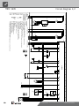
Bypass compressor 1
Time relay bypass compressor 1
STB
K24
M1
Contactor for compressor 1
M16
E22
b
l
KT1
Compressor 1
VD1
K10
1
bl
ZW1 Auxiliary heating
Heating circulation pump
K23
Safety temperature limiter heating element
ZW1
-E22
Brine pump
HUP
BUP Accessories: Process water for changeover valve
M4
Operating materials
X10
Legend:
Terminal strip in switchbox of heat pump; N/PE distribution for external 230V units
Q5
2
1~N/PE/230V/50Hz
2
-K10
1~N/PE/230V/50Hz
br
2
EVU Energy supplier contact; closed on release; bridge if no blocking interval
High-pressure switch
1L1/1L2/1L3/1N1/1N2/1N3/PE: power supply, additional heating
L/N/PE: Control supply
b
r
1~N/PE/230V/50Hz
Function
EVU
1
230VAC
Controller board; Attention: I-max = 6A/230VAC
Operating condenser 55µF for compressor 1
2
rt
bl
bl
F1
Mixer; installed with cooling option
1~N/PE/230V/50Hz
1
UK817260h
Contactor for auxiliary heating
Q1
1~N/PE/230V/50Hz
Q11
VD1
BOSUP
bl
3
MIS
F2
Starting current limit compressor 1
M3
3
NDP
L1/N/PE: Power supply output compressor
1~N/PE/230V/50Hz
Low-pressure switch
HDP
1
22.06.2015
ÄM 045/2013
1
Escher F.
g
1/2
Achim Pfleger
1 x 230V
17.05.1999
SWC 120S
817260
1 2 3 4 5 6 7 8 9 10 11 12 13 14 15 16
1 2 3 4 5 6 7 8 9 10 11 12 13 14 15 16
h ÄM 041/2014
Bl von Anz
Name
Datum
Zustand
Blatt-Nr.
Bearb.
Datum
Änderung
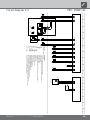
We reserve the right to modify technical specifications without prior notice.
83060000eUK © ait-deutschland GmbH
Circuit diagram 1/2SWC 120S
Sayfa yükleniyor...
Sayfa yükleniyor...
Sayfa yükleniyor...
Sayfa yükleniyor...
Sayfa yükleniyor...
Sayfa yükleniyor...
Sayfa yükleniyor...
Sayfa yükleniyor...
-
 1
1
-
 2
2
-
 3
3
-
 4
4
-
 5
5
-
 6
6
-
 7
7
-
 8
8
-
 9
9
-
 10
10
-
 11
11
-
 12
12
-
 13
13
-
 14
14
-
 15
15
-
 16
16
-
 17
17
-
 18
18
-
 19
19
-
 20
20
-
 21
21
-
 22
22
-
 23
23
-
 24
24
-
 25
25
-
 26
26
-
 27
27
-
 28
28


İlgili makaleler
-
Alpha innotec HTD S El kitabı
-
-
-
-
-
-
-
-
-