
UK
83062600fUK – Translation of the original operating manual
Supplement to Operating Manual
Device Information
Hydraulic Module HMD 1/(R)SE
Accessories for
Dual Air / Water Heat Pumps

2
Subject to change without notice | 83062600fUK – Translation of the original operating manual | ait-deutschland GmbH
Please read rst
The “Model Device Information” is an integral part
of the product. It supplements the operating manual
“HMD 1/E Air/Water Heat Pump, Outdoor Installation”.
In addition to this “Model Device Information”, the op-
erating manual “HMD 1/E” must also be available to
you.
Since this “Model Device Information” was written for
several dierent models of the unit, always comply
with the parameters for the respective model.
The “Model Device Information” is intended only for
persons assigned to work on or operate the unit. Treat
all constituent parts condentially. The information
contained herein is protected by copyright. No part of
this information may be reproduced, transmitted, cop-
ied, stored in electronic data systems or translated into
another language, either wholly or in part, without the
express written permission of the manufacturer.

3
Subject to change without notice | 83062600fUK – Translation of the original operating manual | ait-deutschland GmbH
Contents
INFORMATION FOR OPERATORS AND
QUALIFIED SPECIALISTS
Please read rst ........................................................ 2
INFORMATIONS FOR QUALIFIED
TECHNICIANS
Technical data/scope of delivery
HMD 1/SE ............................................................ 4
HMD 1/RSE .......................................................... 5
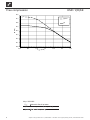
Performance curves
Free compression................................................. 6
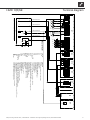
Terminal diagram ....................................................... 7
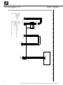
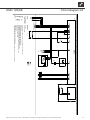
Circuit diagrams ........................................................ 8

4
Subject to change without notice | 83062600fUK – Translation of the original operating manual | ait-deutschland GmbH
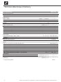
Unit designation HMD 1/SE
Accessory for heat pump model
LWD 50ASX - LWD 70ASX ı LWD 50ARSX - LWD 70ARSX
• applicable ı — not applicable • ı —
Functionally necessary
• applicable ı — not applicable •
Installation location
Indoors ı Outdoors
• applicable ı — not applicable • ı —
Maximum indoor temperature
°C —
Maximum relative humidity
% —
Conformity
CE •
Heating circuit
Heating circuit eciency pump
integrated: • yes — no —
Heating circuit free compression ∆p (factory setting) ı Maximum free compression ∆pmax ı Volume ow
bar ı bar ı l/h 0,46 ı 0,54 ı 1600
Volume ow: minimum ow rate ı maximum ow rate
l/h 900 ı 2000
max. permissible operating pressure
bar 3
Integrated expansion vessel ı Volume ı Initial pressure
• yes — no ı l ı bar • ı 12 ı 1,5
Buer tank
integrated: • yes — no —
Heat metering and/or ow rate display
integrated: • yes — no •
General unit data
Housing dimensions (Height ı Width ı Depth)
mm ı mm ı mm 695 ı 550 ı 330
Total weight
kg 25
Connections
Heating water inlet (forward flow)
… R 1" internal
Hot water outflow (forward flow)
… R 1" internal
Electrics
Voltage code ı three-phase circuit breaker heat pump 5 kW **)
… ı A 1~/N/PE/230V/50Hz ı C16
Voltage code ı three-phase circuit breaker heat pump 7 kW **)
… ı A 1~/N/PE/230V/50Hz ı C20
Voltage code ı circuit breaker control voltage **)
… ı A 1~/N/PE/230V/50Hz ı B16
Voltage code ı circuit breaker electric heating element 1~230V**)
… ı A 1~/N/PE/230V/50Hz ı B32
Voltage code ı circuit breaker electric heating element 1~230V**)
… ı A 3~/PE/230V/50Hz ı B16A
Protection type
IP 20
Output electric heating element 3 ı 2 ı 1 phase
kW ı kW ı kW 6 ı 4 ı 2
Heating circuit pump: maximum power consumption ı current consumption
kW ı A 0,07 ı 0,31
Safety equipment
Safety assembly heating circuit ı Safety assembly heat source
in scope of delivery: • yes — no • ı —
Heating and heat pump regulator
in scope of delivery: • yes — no •
Overow valve
integrated: • yes — no —
**) comply with local regulations
813312b
Technical data / scope of delivery

5
Subject to change without notice | 83062600fUK – Translation of the original operating manual | ait-deutschland GmbH
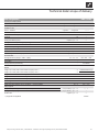
Unit designation HMD 1/RSE
Accessory for heat pump model
LWD 50ASX - LWD 70ASX ı LWD 50ARSX - LWD 70ARSX
• applicable ı — not applicable • ı —
Functionally necessary
• applicable ı — not applicable •
Installation location
Indoors ı Outdoors
• applicable ı — not applicable • ı —
Maximum indoor temperature
°C 35
Maximum relative humidity
% 60
Conformity
CE •
Heating circuit
Heating circuit eciency pump
integrated: • yes — no —
Heating circuit free compression ∆p (factory setting) ı Maximum free compression ∆pmax ı Volume ow
bar ı bar ı l/h 0,46 ı 0,54 ı 1600
Volume ow: minimum ow rate ı maximum ow rate
l/h 900 ı 2000
max. permissible operating pressure
bar 3
Integrated expansion vessel ı Volume ı Initial pressure
• yes — no ı l ı bar • ı 12 ı 1,5
Buer tank
integrated: • yes — no —
Heat metering and/or ow rate display
integrated: • yes — no •
General unit data
Housing dimensions (Height ı Width ı Depth)
mm ı mm ı mm 695 ı 550 ı 330
Total weight
kg 25
Connections
Heating water inlet (forward flow)
… R 1" internal
Hot water outflow (forward flow)
… R 1" internal
Electrics
Voltage code ı three-phase circuit breaker heat pump 5 kW **)
… ı A 1~/N/PE/230V/50Hz ı C16
Voltage code ı three-phase circuit breaker heat pump 7 kW **)
… ı A 1~/N/PE/230V/50Hz ı C20
Voltage code ı circuit breaker control voltage **)
… ı A 1~/N/PE/230V/50Hz ı B16
Voltage code ı circuit breaker electric heating element 1~230V**)
… ı A 1~/N/PE/230V/50Hz ı B32
Voltage code ı circuit breaker electric heating element 1~230V**)
… ı A 3~/PE/230V/50Hz ı B16A
Protection type
IP 20
Output electric heating element 3 ı 2 ı 1 phase
kW ı kW ı kW 6 ı 4 ı 2
Heating circuit pump: maximum power consumption ı current consumption
kW ı A 0,07 ı 0,31
Safety equipment
Safety assembly heating circuit ı Safety assembly heat source
in scope of delivery: • yes — no • ı —
Heating and heat pump regulator
in scope of delivery: • yes — no •
Overow valve
integrated: • yes — no —
**) comply with local regulations
813313b
Technical data / scope of delivery

6
Subject to change without notice | 83062600fUK – Translation of the original operating manual | ait-deutschland GmbH
0,0
0,1
0,2
0,3
0,4
0,5
0,6
0,7
0,8
0,0 0,5 1,0 1,5 2,0 2,5 3,0
∆
p (bar)
∆pmax
∆p
“ ” (m
3
/h)
Bezeichnung:
D t i 812030 F i P HMD 1/( R )E
812031
Seite: 1/1
Zeichnungsnummer:
Legende:
“ ”
Volumenstrom Heizwasser in m
3
/
h
∆p freie Pressung (Werkseinstellung)
∆pmax freie Pressung maximal
Freie Pressung HMD 1/( R )E
812031
- /PEP 001-2012 / Liska / 23.05.2012
Änd./ÄM/Ersteller/Datum
Keys: UK812031
“” Volumetric ow of hot water
∆p Free compression (factory setting)
∆pmax Maximum free pressing
Free compression HMD 1/(R)SE

7
Subject to change without notice | 83062600fUK – Translation of the original operating manual | ait-deutschland GmbH
-F10 -F11 -F12
A1
A2
-Q14
-F13
A1
A2
1N2
PE
2
1L2
3
Pump for mixing circuit 1
1
TB1
bl
No function
Sensor mixing circuit 1
1
BUP
MZ1/MIS
br
X7:1L1,1N1,PE
Control signal of additional heat generator 1; internally wired
Charge/discharge/cooling mixer 1 closed
Hot water circulating pump/switching valve
External sensor
EVU
MOT
FP1
ZW1
X0-X4
Motor protection
Heating circuit circulating pump
Cut out compressor
3
TRL
Terminal in hydraulic module; power supply additional heating
RFV
PEX
Terminals
TB1
External return sensor
HUP
L1
MA1/MIS
Terminal strips on controller board (see sticker)
-X4
circulation pump
ZW2/SST
Accessories: Remote control
TBW
A4
Terminal in hydraulic module for compressor output
Energy supplier contact; closed on release; bridge if no blocking interval
TA
X10
A2
ZUP
Terminal strip in hydraulic module switch box; N/PE distribution for external 230V devices
Auxiliary circulation pump
RFV
X7:L1,N,PE
Control signal of additional heat generator 2
N
ZUP
External unit
HUP
Control element
TB1
3
MOT
LIN
Hot water gauge/thermostat
L1
X7
A3
PE
ZIP
M
-X
A4
L1
TA
GND
L1
X10
Charge/discharge/cooling mixer 1 open
TBW
N
EVU
Hot water or buffer storage tank
BUP
HUP
N
1~N/PE/230V/50Hz
2
Name
ZIP
1~N/PE/230V/50Hz
3
ZW2/SST
GND
X7
A1
TA
GND
Dual air-water
Information on fuses can be found in the technical data
3
ZW1
M
BUP
MZ1
MIS
EVU
4
L
1
1L3
1N3
PE
ZW2
2
PE
F13
Function
1L1
FP1
LIN
connection control unit --> external unit
TBW
ZIP
X7
1~N/PE/230V/50Hz
3
A5
-X0
Cut out auxiliary heating 2
UK831176b
ZW2
MA1
Cut out auxiliary heating 1
Q14
Legend:
Cut out controller unit
Contactor electric heating element hot water or buffer tank
PE
L
F11
F10
Sub-distribution unit internal installation
A2
GND
RFV
PE
Controller board; Attention: I-max = 6A/230VAC
F12
2
GND
X10
A5
-X3
A1
1N1
-X10
ZUP
-X7
-X2
A3
VBO
TRL
PEX
GND
ASD
FP1
1~N/PE/230V/50Hz
Terminal diagram LWD 230V
831176
Achim Pfleger 25.05.2011
b ÄM 045/2013
1 2 3 4 5 6 7 8 9 10 11 12 13 14 15
16
1 2 3 4 5 6 7 8 9 10 11 12 13 14 15 16
1/1
1
23.07.2013
ÄM 034/2011
10X607 - 10X608;
a
Achim Pfleger
10X603 - 10X604;
Blatt-Nr.
Zustand
Änderung
Bearb.
Datum
Name
Bl von Anz
Datum
HMD 1/(R)SE Terminal diagram

8
Subject to change without notice | 83062600fUK – Translation of the original operating manual | ait-deutschland GmbH
1L1
-X7
1L2
1L3
2
1
-Q5
/2.8
1N1
-X7
4
3
5
31
6
42
-E22
ZW1
1N2
6
5
1N3
PE L1
-X7
N PE
L N PE
1
-X0
2
123
PE
3 4
E22
Operating materials
X7
UK817383c
Control element
1L1,1L2,1L3,1N1,1N2,1N3,PE; Power supply Aux. heating
1~N/PE/230V/50Hz
Contactor for auxiliary heating
K11
ZW1
X7
Q5
Auxiliary heating
Legend:
1~N/PE/230V/50Hz
Function
-K11
Unit connection
1
X7
Cable
P E2
LIN
12V/LIN/GND
X7
1~N/PE/230V/50Hz L1,N,PE; Power supply compressor;
LIN
1~N/PE/230V/50Hz
Power supply, compressor output --> external unit
LIN bus
Hydraulic module HMD 230V
817383
Achim Pfleger 25.08.2011
c ÄM 045/2013
1 2 3 4 5 6 7 8 9 10 11 12 13 14 15 16
1 2 3 4 5 6 7 8 9 10 11 12 13 14 15 16
1/2
1
24.07.2013
PEP 011/2012
150712;
b
Achim Pfleger
150708;
Blatt-Nr.
Zustand
Änderung
Bearb.
Datum
Name
Bl von Anz
Datum
Circuit diagram 1/2 HMD 1/(R)SE

9
Subject to change without notice | 83062600fUK – Translation of the original operating manual | ait-deutschland GmbH
PE N L
L
-X0
L
-X10
N
N
PE
PE
L
-X0
L L
MOT
-X2
EVU
-X2
ASD
-X2
1
2
-F6
HUP
-X3
M
1
L N PE
-M4
HUP
M
1
br bl PE
br
bl
bk
-M5
HUP
ZW1
-X3
ϑ
-STB
A1
A2
-Q5
ZW1
0-10V
12
GND
12
ϑ
TVL
-X5
-R5
TVL
GND
ϑ
TRL
-X5
-R4
TRL
GND
0-10V
8
GND
8
AO2
-X6
GND
21
/1.3
43
/1.4
65
/1.4
X10
X10
ASD
ZW1
-K12
Legend:
1~N/PE/230V/50Hz
EVU
Return sensor
Supply terminals in switchbox of hydraulic module; N/PE distribution for external 230V units
R4
STB
Contactor for auxiliary heating
M4
2
K10
Flow sensor;
Function
Safety temperature limiter, additional heating
F6
TRL
Energy supplier contact; closed on release; bridge if no blocking interval
HUP
br
C
bl
1~N/PE/230V/50Hz
EVU
1
HUP Heating pump energy efficiency; installed in Energy Efficiency optionM5
K12 Comfort plate; installed in Energy Efficiency option
Flow sensor
Operating materials
Q5
1
Controller supply
R5
-K10
Heating pump; not required in the Energy Efficiency option
TVL
230VAC
UK817383c
Controller board; Attention: I-max = 6A/230VAC
Hydraulic module HMD 230V
817383
Achim Pfleger 25.08.2011
c ÄM 045/2013
1 2 3 4 5 6 7 8 9 10 11 12 13 14 15 16
1 2 3 4 5 6 7 8 9 10 11 12 13 14 15 16
2/2
2
24.07.2013
PEP 011/2012
150712;
b
Achim Pfleger
150708;
Blatt-Nr.
Zustand
Änderung
Bearb.
Datum
Name
Bl von Anz
Datum
HMD 1/(R)SE Circuit diagram 2/2

10
Subject to change without notice | 83062600fUK – Translation of the original operating manual | ait-deutschland GmbH

11
Subject to change without notice | 83062600fUK – Translation of the original operating manual | ait-deutschland GmbH

ait-deutschland GmbH
Industriestrasse 3
95359 Kasendorf, Germany
E info@alpha-innotec.de
W www.alpha-innotec.de
alpha innotec – an ait-deutschland GmbH brand
UK
-
 1
1
-
 2
2
-
 3
3
-
 4
4
-
 5
5
-
 6
6
-
 7
7
-
 8
8
-
 9
9
-
 10
10
-
 11
11
-
 12
12


İlgili makaleler
-
Alpha innotec HMD S El kitabı
-
-
-
-
-
-
-
-
-