
UK
Supplement to Operating Manual
Device Information
LW A – Series
Air/Water Heat Pumps
Outdoor Installation
83063200fUK – Translation into English of the
original German operating manual

2
Subject to change without notice | 83063200fUK – Translation into English of the original German operating manual | ait-deutschland GmbH
Please read rst
The “Special Model Device Information” is an integral
part of the product. It supplements the operating manu-
al “Air/Water Heat Pump, Outdoor Installation”. In addi-
tion to this “Special Model Device Information”, the op-
erating manual “Air/Water Heat Pumps, Outdoor Instal-
lation” must also be available to you.
Since this “Special Model Device Information” was writ-
ten for several different models of the unit, always com-
ply with the parameters for the respective model.
The “Special Model Device Information” is intended on-
ly for persons assigned to work on or operate the unit.
Treat all constituent parts condentially. The informa-
tion contained herein is protected by copyright. No part
of this information may be reproduced, transmitted,
copied, stored in electronic data systems or translated
into another language, either wholly or in part, without
the express written permission of the manufacturer.

3
Subject to change without notice | 83063200fUK – Translation into English of the original German operating manual | ait-deutschland GmbH
Contents
INFORMATION FOR USERS AND QUALIFIED
PERSONNEL
PLEASE READ FIRST .................................................................. 2
INFORMATIONS FOR QUALIFIED PERSONNEL
TECHNICAL DATA/SCOPE OF DELIVERY
LW 81AX, LW 81ASX LW 121ASX ....................................4
PERFORMANCE CURVES
Heating capacity/COP / Power consumption /
Heat pump pressure loss
LW 81A X ................................................................................6
LW 81ASX ..............................................................................7
LW 121ASX ............................................................................8
DIMENSIONAL DRAWINGS
LW 121ASX ............................................................................9
INSTALLATION PLANS
LW 121ASX ..........................................................................10
TERMINAL DIAGRAMS
LW 81A X .............................................................................. 11
LW 81ASX • LW 121ASX ................................................... 12
CIRCUIT DIAGRAMS
LW 81A X .............................................................................. 13
LW 81ASX ............................................................................15
LW 121ASX ..........................................................................17
EC DECLARATION OF CONFORMITY .............................. 19

4
Subject to change without notice | 83063200fUK – Translation into English of the original German operating manual | ait-deutschland GmbH
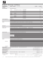
Model designation
Heat pump type Brine/water ı Air/water ı Water/water • applicable ı — not applicable
Installation location Indoors ı Outdoors • applicable ı — not applicable
Conformity CE
Performance data Heating capacity/COP at
A7/W35 Standard point acc. to EN14511
2 Compressors
1 Compressor
kW ı …
kW ı …
A7/W45 Standard point acc. to EN14511
2 Compressors
1 Compressor
kW ı …
kW ı …
A2/W35
Operating point according to
EN14511
2 Compressors
1 Compressor
kW ı …
kW ı …
A10/ W35
Operating point according to
EN14511
2 Compressors
1 Compressor
kW ı …
kW ı …
A-7/ W35
Operating point according to
EN14511
2 Compressors
1 Compressor
kW ı …
kW ı …
A-15/W65
2 Compressors
1 Compressor
kW ı …
kW ı …
Limits of application Heating circuit °C
Heat source °C
Additional operating points °C
Sound Internal sound pressure level (open air test field, distance of 1m around the engine, average) dB(A)
External sound pressure level (open air test eld, distance of 1m around the air supplies, average) (2x 1m original straight air duct) dB(A)
Sound power inside dB(A)
Sound power outside dB(A)
Heat source Air volume flow at maximum external compression m³/h
Maximum external pressure Pa
Heating circuit Volume flow: minimum flow rate ı nominal flow rate A7/W35 EN14511 ı maximum flow rate l/h
Pressure loss heat pump ∆p ı volume flow bar ı l/h
Free compression heat pump ∆p ı volume flow bar ı l/h
Content of buffer tank l
3-way valve, heating/hot water …
General unit data Dimensions (see dimensional drawing for the specified unit size) unit size
Total weight kg
Connections Heating circuit …
Heat source …
Refrigerant Refrigerant type ı Quantity … ı kg
Free cross section, air channels mm
Cross section, condensate water / length from unit mm ı m
Electric Voltage code ı all-pole circuit breaker heat pump **) … ı A
Voltage code ı circuit breaker control voltage **) … ı A
Voltage code ı circuit breaker electric heating element **) ı A
Heat Pump Effective power consumption in standard point A7/W35 according to EN14511: Power consumption ı current consumption ı cosφ kW ı A ı …
Maximum device current within the limits of application A
Starting current: direct ı with soft starter A ı A
Protection type IP
Output electric heating element 3 ı 2 ı 1 phase kW ı kW ı kW
Components Circulating pump heating circuit at nominal flow rate: Power consumption ı current consumption kW ı A
Safety equipment Safety component heating circuit ı Safety component heat source Includ. in sc. of del.: • yes — no
Heating and heat pump regulator Includ. in scope of delivery: • yes — no
Control and sensor wire Includ. in scope of delivery: • yes — no
Power cable to unit Includ. in scope of delivery: • yes — no
Electronic soft starter integrated: • yes — no
Expansion vessels Heat source: Scope of delivery ı Volume ı Initial pressure • yes — no ı l ı bar
Overflow valve integrated: • yes — no
Vibration decouplers Heating circuit ı heat source Included in scope of delivery: • yes — no
UK813517
*) depending on components tolerances and flow **) comply with local regulations n.n. = not detectable w.w. = to choice
¹) hot water return ²) hot water flow
Technical data/scope of delivery

5
Subject to change without notice | 83063200fUK – Translation into English of the original German operating manual | ait-deutschland GmbH
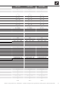
LW 81ASX
— ı • ı —
— ı •
•
—
9,8 ı 3,8
—
9,4 ı 3,0
—
8,0 ı 3,1
—
10,2 ı 4,1
—
6,5 ı 2,6
—
—
20 – 58 (60)*)
-20 – 35
—
—
50
65
3000
—
1200 ı 1750 ı 2200
0,12 ı 1750
— ı —
—
—
1
145
R1“AG
—
R404A ı 2,6
—
30 ı 1
1~/N/PE/230V/50Hz ı C20
1~/N/PE/230V/50Hz ı B10
1~/N/PE/230V/50Hz ı B32
2,6 ı 11,3 ı 1
17, 4
97 ı 38
24
6 ı 4 ı 2
— ı —
— ı —
—
—
—
•
— ı — ı —
—
—
813531
LW 81AX
— ı • ı —
— ı •
•
—
9,7 ı 3,9
—
9,2 ı 3,1
—
8,0 ı 3,3
—
10,3 ı 4,2
—
6,4 ı 2,7
—
—
20 – 58 (60)*)
-20 – 35
—
—
50
65
3000
—
1200 ı 1750 ı 2200
0,12 ı 1750
— ı —
—
—
1
145
R1”AG
—
R404A ı 2,6
—
30 ı 1
3~/PE/400V/50Hz ı C10
1~/N/PE/230V/50Hz ı B10
3~/N/PE/400V/50Hz ı C10
2,5 ı 4,8 ı 0,75
8,4
45 ı 22
24
6 ı 4 ı 2
— ı —
— ı —
—
—
—
•
— ı — ı —
—
—
813530
LW 121ASX
— ı • ı —
— ı •
•
—
12,1 ı 3,7
—
11,3 ı 3,0
—
11,5 ı 3,2
—
12,2 ı 4,0
—
9,2 ı 2,5
—
—
20¹ – 50²
-20 – 35
—
—
51
—
59
4000
—
1650 ı 2500 ı 3100
0,09 ı 2500
— ı —
—
—
2
265
R1”AG
—
R404A ı 3,6
—
30 ı 1
1~/N/PE/230V/50Hz ı C32
1~/N/PE/230V/50Hz ı B10
1~/N/PE/230V/50Hz ı B40
3,3 ı 14,4 ı 1,0
30
150 ı 45
24
9 ı 6 ı 3
— ı —
— ı —
—
—
—
•
— ı — ı —
—
—
813532c
Model designation
Heat pump type Brine/water ı Air/water ı Water/water • applicable ı — not applicable
Installation location Indoors ı Outdoors • applicable ı — not applicable
Conformity CE
Performance data Heating capacity/COP at
A7/W35 Standard point acc. to EN14511
2 Compressors
1 Compressor
kW ı …
kW ı …
A7/W45 Standard point acc. to EN14511
2 Compressors
1 Compressor
kW ı …
kW ı …
A2/W35
Operating point according to
EN14511
2 Compressors
1 Compressor
kW ı …
kW ı …
A10/ W35
Operating point according to
EN14511
2 Compressors
1 Compressor
kW ı …
kW ı …
A-7/ W35
Operating point according to
EN14511
2 Compressors
1 Compressor
kW ı …
kW ı …
A-15/W65
2 Compressors
1 Compressor
kW ı …
kW ı …
Limits of application Heating circuit °C
Heat source °C
Additional operating points °C
Sound Internal sound pressure level (open air test field, distance of 1m around the engine, average) dB(A)
External sound pressure level (open air test eld, distance of 1m around the air supplies, average) (2x 1m original straight air duct) dB(A)
Sound power inside dB(A)
Sound power outside dB(A)
Heat source Air volume flow at maximum external compression m³/h
Maximum external pressure Pa
Heating circuit Volume flow: minimum flow rate ı nominal flow rate A7/W35 EN14511 ı maximum flow rate l/h
Pressure loss heat pump ∆p ı volume flow bar ı l/h
Free compression heat pump ∆p ı volume flow bar ı l/h
Content of buffer tank l
3-way valve, heating/hot water …
General unit data Dimensions (see dimensional drawing for the specified unit size) unit size
Total weight kg
Connections Heating circuit …
Heat source …
Refrigerant Refrigerant type ı Quantity … ı kg
Free cross section, air channels mm
Cross section, condensate water / length from unit mm ı m
Electric Voltage code ı all-pole circuit breaker heat pump **) … ı A
Voltage code ı circuit breaker control voltage **) … ı A
Voltage code ı circuit breaker electric heating element **) ı A
Heat Pump Effective power consumption in standard point A7/W35 according to EN14511: Power consumption ı current consumption ı cosφ kW ı A ı …
Maximum device current within the limits of application A
Starting current: direct ı with soft starter A ı A
Protection type IP
Output electric heating element 3 ı 2 ı 1 phase kW ı kW ı kW
Components Circulating pump heating circuit at nominal flow rate: Power consumption ı current consumption kW ı A
Safety equipment Safety component heating circuit ı Safety component heat source Includ. in sc. of del.: • yes — no
Heating and heat pump regulator Includ. in scope of delivery: • yes — no
Control and sensor wire Includ. in scope of delivery: • yes — no
Power cable to unit Includ. in scope of delivery: • yes — no
Electronic soft starter integrated: • yes — no
Expansion vessels Heat source: Scope of delivery ı Volume ı Initial pressure • yes — no ı l ı bar
Overflow valve integrated: • yes — no
Vibration decouplers Heating circuit ı heat source Included in scope of delivery: • yes — no
UK813517
*) depending on components tolerances and flow **) comply with local regulations n.n. = not detectable w.w. = to choice
¹) hot water return ²) hot water flow

6
Subject to change without notice | 83063200fUK – Translation into English of the original German operating manual | ait-deutschland GmbH
Bezeichnung:
Seite: 1/1
Verdichter
Temp„
Qh
Pe
COP
∆p”
VD
Leistungsaufnahme
Coefficient of performance / Leistungszahl
Legende: DE823129L/170408
823157
“”
Druckverlust Wärmepumpe
Volumenstrom Heizwasser
Temperatur Wärmequelle
Heizleistung
Datei: 823157 Leistungs- Druckverlustkurven LW81AX.xls
Zeichnungsnummer: 823157
Änd./Ä.M./Ersteller/Datum
- / PEP009-2010 / Opel / 18.08.10
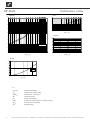
Leistungs-Druckverlustkurven
LW 81AX
Qh (kW)
0
2
4
6
8
10
12
14
16
18
-20 -15 -10 -5 0 5 10 15 20 25 30 35
Temp„ (°C)
35°C 1VD
50°C 1VD
COP
1
2
3
4
5
6
7
-20 -15 -10 -5 0 5 10 15 20 25 30 35
Temp„ (°C)
Pe (kW)
0
1
2
3
4
5
-20 -15 -10 -5 0 5 10 15 20 25 30 35
Temp„ (°C)
∆p (bar)
0,0
0,1
0,2
0,3
0,4
0,0 0,5 1,0 1,5 2,0 2,5 3,0
“” (m³/h)
∆p”
Legend: UK823129L/170408
“” Volume ow, heating water
Temp„ Temperature, heat source
Qh Heating capacity
Pe Power consumption
COP Coefcient of performance / efciency rating
∆p” Pressure loss heat pump
VD Compressor(s)
Performance curves LW 81AX

7
Subject to change without notice | 83063200fUK – Translation into English of the original German operating manual | ait-deutschland GmbH
Bezeichnung:
Seite: 1/1
Datei: 823158 Leistungs- Druckverlustkurven LW81ASX.xls
Zeichnungsnummer: 823158
Änd./Ä.M./Ersteller/Datum
- / PEP009-2010 / Opel / 14.07.10
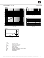
Leistungs-Druckverlustkurven
LW 81ASX
“”
Druckverlust Wärmepumpe
Volumenstrom Heizwasser
Temperatur Wärmequelle
Heizleistung
Legende: DE823129L/170408
823158
Verdichter
Temp„
Qh
Pe
COP
∆p”
VD
Leistungsaufnahme
Coefficient of performance / Leistungszahl
Qh (kW)
0
2
4
6
8
10
12
14
16
18
-20 -15 -10 -5 0 5 10 15 20 25 30 35
Temp„ (°C)
35°C 1VD
50°C 1VD
COP
1
2
3
4
5
6
7
-20 -15 -10 -5 0 5 10 15 20 25 30 35
Temp„ (°C)
Pe (kW)
0
1
2
3
4
5
-20 -15 -10 -5 0 5 10 15 20 25 30 35
Temp„ (°C)
∆p (bar)
0,0
0,1
0,2
0,3
0,4
0,0 0,5 1,0 1,5 2,0 2,5 3,0
“” (m³/h)
∆p”
Legend: UK823129L/170408
“” Volume ow, heating water
Temp„ Temperature, heat source
Qh Heating capacity
Pe Power consumption
COP Coefcient of performance / efciency rating
∆p” Pressure loss heat pump
VD Compressor(s)
Performance curves
LW 81ASX

8
Subject to change without notice | 83063200fUK – Translation into English of the original German operating manual | ait-deutschland GmbH
Bezeichnung:
Seite: 1/1
VD
Leistungsaufnahme
Coefficient of performance / Leistungszahl
Qh
Pe
COP
∆p”
Legende: DE823129L/170408
823159
- / PEP009-2010 / Opel / 02.09.10
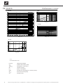
Leistungs-Druckverlustkurven
LW 121 ASX
“”
Druckverlust Wärmepumpe
Volumenstrom Heizwasser
Temperatur Wärmequelle
Heizleistung
Verdichter
Temp„
Änd./Ä.M./Ersteller/Datum
Datei: 823159 Leistungs- Druckverlustkurven LW 121 (A).xls
Zeichnungsnummer: 823159
Qh (kW)
5
7
9
11
13
15
17
19
21
23
25
-20 -15 -10 -5 0 5 10 15 20 25 30 35
Temp„ (°C)
35°C 1VD
50°C 1VD
COP
1
2
3
4
5
6
7
-20 -15 -10 -5 0 5 10 15 20 25 30 35
Temp„ (°C)
Pe (kW)
2
3
4
5
6
-20 -15 -10 -5 0 5 10 15 20 25 30 35
Temp„ (°C)
∆p (bar)
0,0
0,1
0,2
0,3
0,4
0,0 0,5 1,0 1,5 2,0 2,5 3,0 3,5 4,0 4,5 5,0
“” (m³/h)
∆p”
Legend: UK823129L/170408
“” Volume ow, heating water
Temp„ Temperature, heat source
Qh Heating capacity
Pe Power consumption
COP Coefcient of performance / efciency rating
∆p” Pressure loss heat pump
VD Compressor(s)
Performance curvesLW 121ASX

9
Subject to change without notice | 83063200fUK – Translation into English of the original German operating manual | ait-deutschland GmbH
726
315
1774
C C
4
1353
848
105
175
275
355
726
826
45
105
195
4
1
2
3
LR
A
B
Legende: DE819351d
Technisches Änderungen vorbehalten.
Alle Maße in mm.
A Vorderansicht
B Seitenansicht von links
C Draufsicht
(Schnitt, ohne Fassade und Hutzen)
1 Heizwasser Austritt (Vorlauf) R 1"
2 Heizwasser Eintritt (Rücklauf) R 1"
3 Kondensatschlauch Außen-
36x3
4 Grundplatte
LR Luftrichtung
8
7
6
5
4
3
2
1
www.ait-deutschland.eu
D - 95359 Kasendorf
Industriestraße 3
ait-deutschland GmbH
1
1
DM
17.3.2014
ÄM 007/2014
d
Ers. d.
Ers. f.
A
B
C
D
E
F
F
E
D
C
B
A
4
3
2
1
Benennung
c
b
a
Zust.
Änderungstext
PEP 023/2010
PEP 001/2013
ÄM 999/2010
Datum
26.4.2010
25.10.2010
5.2.2014
Von
RK
RA
RA
Blatt
von
Werkstoff
Gewicht
Maßstab
1:20
Det. Maßstab
Datum
Name
Erstellt
Gepr.
Norm.
17.3.2014
Markieton
toleranz
Allgemein-
Oberflächen
ArtikelNr.
Schutzvermerk ISO 16016 beachten
DIN ISO 2768 -c
Markieton
17.3.2014
koex1
5.3.2014
RA
RA
RK
RK
5.2.2014
25.10.2010
26.4.2010
22.3.2010
ÄM 999/2010
PEP 001/2013
PEP 023/2010
PEP 026/2009
-
a
b
c
819351
Maßbild LW 101A, LW 100H-A
d
ÄM 007/2014
17.3.2014
DM
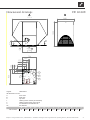
Legend: UK819351a
All dimensions in mm.
A Front view
B Side view
C Top view
1 Heating water outow (forward ow)
2 Heating water inow (return ow)
3 Condensate hose diameter 36
LR Air direction
B₁ B₂ B₃ B₄ B₅ B₆ T₁ T₂ T₃ T₄ H₁ H₂ 1 2
LW 121ASX 91 160 260 341 694 1774 56 117 206 848 315 1353 R 1“ R 1“
Dimensional drawings LW 121ASX

10
Subject to change without notice | 83063200fUK – Translation into English of the original German operating manual | ait-deutschland GmbH
50
>80
3
4
6
≥800≥950
≥2700
≥4200
290
190
137
75
926
>
1600
≥950 ≥2400
826
50
>
1300
3
4
LR
2
1
5
C
LR
A
≥...
Aufstellungsplan ist gültig für:
PL 2009 und älter: LW 100A-120A, LW 150HA
PL 2010 LW 101A, LW 150HA
Ab Nov 2010 LW 101A, LW 100HA
8
7
6
5
4
3
2
1
www.alpha-innotec.de
D - 95359 Kasendorf
Industriestraße 3
Alpha-InnoTec GmbH
Schutzvermerk nach DIN 34 beachten
1
1
Ers. d.
Ers. f.
A
B
C
D
E
F
F
E
D
C
B
A
4
3
2
1
Benennung
Aufstellungs- Sockelplan
BG2 LW 101A, LW 100HA
819375
a
-
Zust.
Änderungstext
PEP 026/2009
PEP 023/2010
Datum
18.3.2010
25.10.2010
RA
Von
RA
Blatt
von
Werkstoff
Gewicht
Maßstab
1:50
1:30
Det. Maßstab
Datum
Name
Erstellt
Gepr.
Norm.
18.3.2010
Aepfelbach
25.10.2010
Aepfelbach
toleranz
Allgemein-
Oberflächen
ArtikelNr.
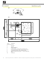
Legend: UK819375a
All dimensions in mm.
A Front view
C Top view
≥ … Minimum clearances
1 Recess in base
2 Local heat pipe for heating water forward/return ow
3 Empty pipe for electric cables, minimum diameter 70mm
4 Condensate discharge, minimum diameter 50mm
5 Water-permeable surface (gravel, …) in the air outlet area
6 Base
LR Air direction
LW 121ASX Installation plan

11
Subject to change without notice | 83063200fUK – Translation into English of the original German operating manual | ait-deutschland GmbH
-F10
-F13 -F14
A1
A2
-K14
-F11
A1
A2
ZIP circulation pump
ZUP
-X9
M
X9
-X8
X8
A5
F11
Distribution box in heat pump; power supply output additional heating
ZW2
5
ZW2/SST
5
54
N
F10
M
-X5
3-pol. Cut out compressor; Attention: Right-hand ro t. eld is mandatory!
Plug on switch box heat pump (gauge line)X52
Cut out controller unit
PE
3~N/PE/400V/50Hz
10
Heat pump
L1
TB1
TA
HUP
A1
6
12
PE
11
BUP
-X1
1
UK831152
HUP
A2
ZW2/SST
-X12
5
MZ1
ZW2
4
RFV
PE
Sub-distribution unit internal installation
M
Auxiliary circulation pump
MIS
Terminal strip in switch box wall regulator; N/PE d istribution for external 230V devices
Distribution box in heat pump; power supply output compressor
7
Ventilator; internally wired
L
7
Control signal of additional heat generator 2
-X0
2
N
A3
VBO
ZUP
-X3
Air water outside
TBW
-X2
MA1
X7
X1/X5 Plugs on controller board (see sticker)
N
HUP
A4
EVU
A1
Terminals in switch box wall regulator
2
3
GND
9
3~PE/400V/50Hz
FP1
BUP
N
Terminals
ZW1
Hot water circulating pump/switching valve
GND
MOT
3
Name
Plug on switch box heat pump (control line)
Control signal of additional heat generator 1; inte rnally wired
Terminal strips on controller board (see sticker)
A2
X0-X4
3
External return sensor
TRL
PE
Pump for mixing circuit 1
11
TBW
8
External sensor
A3
ZUP
BUP
ZW2
A4
3~N/PE/400V/50Hz
1
Inf
or
m
ati
on
on
fus
e
s
c
an
be
foun
d i
n
the
tec
h
ni
c
al
d
ata
ZIP
M
-X52
ZIP
Contactor electric heating element hot water or buf fer tank
Hot water or buer storage tank
-X7
Cut out auxiliary heating 2
K14
PE
Cut out auxiliary heating 1
F14
RFV
X12
A5
VBO
F13
No function
TB1
L1
ZW1
-X4
RFV
Energy supplier contact; closed on release; bridge if no blocking interval
FP1
N
MOT
2
TB1
1~N/PE/230V/50Hz
EVU
GND
Overload protection; internally wired
TRL
Function
B10 A
9
MA1/MIS
TA
GND
Controller board; Attention: I-max = 6A/230VAC
PEX
TA
Legend:
ASD
TBW
8
Charge/discharge/cooling mixer 1 closed
GND
L1
Charge/discharge/cooling mixer 1 open
GND
104
12
PEX
6
Sensor mixing circuit 1
Hot water gauge/thermostat
EVU
Heating circuit circulating pump
MZ1/MIS
Accessories: Remote control
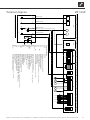
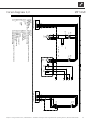
Terminal diagram LWA 70-320 LUX2
831152
Achim Peger 17.11.2008
-
1
2
3 4 5 6 7
8
9
10
11
12
13
14
15
16
1 2 3 4 5 6 7 8 9 10 11 12 13 14 15 16
1/1
1
20.03.2009
10X426 - 10X427; 10X446 - 10X448
Achim Peger
10X410 - 10X412; 10X417 - 10X420; 10X422;
Blatt-Nr.
Zustand
Änderung
Bearb.
Datum
Name
Bl von Anz
Datum
LW 81AXTerminal diagram

12
Subject to change without notice | 83063200fUK – Translation into English of the original German operating manual | ait-deutschland GmbH
-F10 -F13 -F14
A1
A2
-K14
-F11
A1
A2
Plug on switch box heat pump (gauge line)
circulation pump
M
-X8
X8
A5
ZW2
11
ZW2
5
1~N/PE/230V/50Hz
ZIP
3
F10
X9
M
N
3
Distribution box in heat pump; power supply output additional heating
Cut out compressor
F11
ZW2/SST
-X12
Cut out controller unit
X52
L1
TB1
TA
ZW1
Terminals
6
12
Overload protection; internally wired
PE
BUP
1
Heat pump
HUP
10
UK831159
-X1
A1
ZW2/SST
N
PE
5
3
MZ1
MIS
A2
PE
7
Luft Wasser aussen 8 - 15 kW, 1 x 230V
Ventilator; internally wired
-X3
RFV
Distribution box in heat pump; power supply output compressor
Sub-distribution unit internal installation
M
L
Terminal strip in switch box wall regulator; N/PE distribution for external 230V devices
4
7
Control signal of additional heat generator 2
-X0
2
N
A3
VBO
ZUP
-X2
ZUP
Auxiliary circulation pump
X7
A1
-X5
Terminals in switch box wall regulator
-X9
MA1
EVU
X1/X5 Plugs on controller board (see sticker)
2
A4
TBW
3
GND
9
1~PE/230V/50Hz
FP1
BUP
N
Plug on switch box heat pump (control line)
External return sensor
HUP
Control signal of additional heat generator 1; internally wired
External sensor
PE
Cut out auxiliary heating 1
1
Terminal strips on controller board (see sticker)
A3
Name
Pump for mixing circuit 1
BUP
No function
3
GND
TBW
3
PE
MOT
8
X0-X4
1~N/PE/230V/50Hz
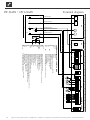
Information on fuses can be found in the technical data
Contactor electric heating element hot water or buffer tank
A4
ZW2
X12
ZIP
M
HUP
-X52
ZIP
Hot water circulating pump/switching valve
A5
F14 Cut out auxiliary heating 2
K14
-X7
F13
Hot water or buffer storage tank
1 x 230V, 8 - 15 kW
ZUP
VBO
RFV
Charge/discharge/cooling mixer 1 closed
Energy supplier contact; closed on release; bridge if no blocking interval
2
L1
ZW1
TB1
TB1
Controller board; Attention: I-max = 6A/230VAC
PEX
N
MOT
FP1
RFV
EVU
Function
1~N/PE/230V/50Hz
TRL
GND
TA
9
-X4
B10 A
GND
MA1/MIS
8
Charge/discharge/cooling mixer 1 open
TA
Legend:
PEX
GND
A2
11
GND
L1
TRL
TBW
4
Sensor mixing circuit 1
10
6 12
MZ1/MIS
EVU
ASD
Hot water gauge/thermostat
Accessories: Remote control
Heating circuit circulating pump
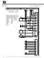
Terminal diagram LWA 80-150 (1x230V) LUX2
831159
Achim Pfleger 16.02.2009
- PEP 018/2008
1
2 3 4 5 6 7 8 9 10 11 12 13 14 15 16
1 2 3 4 5 6 7 8 9 10 11 12 13 14 15 16
1/1
1
17.02.2009
Achim Pfleger
10X421; 10X423 - 10X425; 10X427;
Blatt-Nr.
Zustand
Änderung
Bearb.
Datum
Name
Bl von Anz
Datum
LW 81ASX • LW 121ASX Terminal diagram

13
Subject to change without notice | 83063200fUK – Translation into English of the original German operating manual | ait-deutschland GmbH
LW71-81 A
a
b
c
Legend:
Equipement
3~PE/400V/50Hz
3~N/PE/400V/50Hz
E22
E23
F3
G3
M1
Q1
Q3
Q5
Q11
X8
X9
3~PE/400V/50Hz
ZW1
VENT1
VD1
-X8
UK
Function
Power supply compressor; right-hand rot. field is mandatory!
Power supply aux. heating
Auxiliary heating
Nozzle heating fan
Motor protection fan
Fan
Compressor
Contactor for compressor 1
Contactor fan
Contactor for auxiliary heating
Starting current limit
Power supply compressor; right-hand rot. field is mandatory!
Power supply aux. heating
817332
-Q1
3~
-M1
-Q11
-Q3
3~
-G3
-F3 -E23
3~N/PE/400V/50Hz
-X9
-X10
-Q5
-E22
12345678
12 8
A
B
C
D
E
F
A
B
C
D
E
F
Blatt
Bl.
1
2
3 4567
AIT
817332c
Stromlaufplan
ait-deutschland GmbH
ÄM 029/2010
ÄM 063/2013
ÄM 020/2015
11.10.2010
30.08.2013
08.04.2015
1
L1
2
L2
3
L3
gn/ge
PE
/2.B3
1
3
5
2
4
6
U
V
VD1
W
PE
L1
L2
L3
U
V
W
A1
A2
VD1 L
/2.B1
N-HDP
/2.C1
/2.B3
1
3
5
2
4
6
U1
V1
VENT1
W1
PE
TKTK
ϑ
L Reg
/2.A1
N Reg
/2.B1
MOT
/2.B1
E23
/2.B1
PE
/2.C1
1
1L1
2
1L2
3
1L3
1N
4
1N
gn/ge
1PE
/2.B4
1
3
5
2
4
6
MM
Änderung Datum
Datum
Bearbeiter
Geprüft
NormName
08.04.2015
Pfleger
R.
-M1
123
PE
-G3
123
PE
456 7
1
2
3
4
5
6
PE
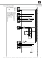
Circuit diagrams 1/2 LW 81AX

14
Subject to change without notice | 83063200fUK – Translation into English of the original German operating manual | ait-deutschland GmbH
LW71-81 A
a
b
c
Legend:
Equipement
B10
F1
F2
K10
Q1
Q3
Q5
R2
R3
R4
R5
R6
R10
STB
X10
X12
X52
AEP
HDP
NDP
VD1
VBO
ZW1
TWE
TWA
TRL
TVL
THG
CW
-X12
-X12
-X10
UK
Function
Defrosting pressostat
High-pressure switch
Low-pressure switch
Defrosting valve
Contactor for compressor 1
Contactor fan
Contactor for auxiliary heating
If installed: heat source input gauge
If installed: heat source outlet gauge
Return sensor
Flow sensor
Hot gas sensor
Encoding resistor
Safety temperature limiter heating element
Terminal in switch box heat pump
Plug on switch box heat pump (control line)
Plug on switch box heat pump (gauge line)
817332
-X10
-F1
442Ohm
-Q1 -Q3
-X10
-K10
STB
-Q5
-F2 -B10
-X52
-X52
-R4 -R5 -R6 -R3
-X7
-R10
-R2
12345678
12 8
A
B
C
D
E
F
A
B
C
D
E
F
Blatt
Bl.
2
2
3 4567
AIT
817332c
Stromlaufplan
ait-deutschland GmbH
ÄM 029/2010
ÄM 063/2013
ÄM 020/2015
11.10.2010
30.08.2013
08.04.2015
L Reg
/1.A6
MOT
/1.B6
VD1 L
/1.B3
E23
/1.B6
N Reg
/1.A6
N-HDP
/1.B3
PE
/1.B6
L1
12
L
MOT
6
N
11
N
-F1
HD
5
HDP
P
VD1
1
A1A2
VD1
VBO
10
A1A2
VBO
-K10
AV
7
28
ZW1
8
ϑ
A1A2
ZW1
-F2
ND
3
c4a1
NDP
P
-B10
ASD
9
AEP
P
1
TRL
ϑ
23
TVL
ϑ
45
THG
ϑ
67
TWA
ϑ
89
29
CW
10
30
11
TWE
ϑ
12
Änderung Datum
Datum
Bearbeiter
Geprüft
NormName
08.04.2015
Pfleger
R.
sw bl
b2 c4
a1
rt sw sw 1
b2 c4
a1
2 PE
LW 81AX Circuit diagram 2/2

15
Subject to change without notice | 83063200fUK – Translation into English of the original German operating manual | ait-deutschland GmbH
L1
-X8
N PE
1L1
-X9
1N PE
1
2
-Q5
/2.9
-E22
ZW1
3
4
5
6
1N
-X10
1
2
-Q1
/2.3
3
4
M
3
T1
T2
T3
PE
-M1
VD1
5
6
L1
-X10
-F5
-C1
14
11
-K6
/2.4
R
RC
L1
S
ON
N
-Q11
-F4
1
2
-Q3
/2.6
3
4
5
6
M
1
U1 U2 PE
-G1
VENT1
TK
TK
-E23
L Reg
/2.1
N Reg
/2.1
MOT
/2.1
R23
/2.1
PE
/2.1
F4 Fuses ventilator
3 PE
Contactor fan
6
Operating condenser 70µF for compressor
1
E23
3
1L1/1N/PE: power supply, additional heating
1~N/PE/230V/50Hz
-M1
Nozzle heating fan
C1
ZW1 Contactor for auxiliary heating
VBO
E22
F3
6
Q5
2
Compressor 1
4
Auxiliary heating
2
Operating materials
Motor protection fan
3
Starting current limit
M1
1~N/PE/230V/50Hz
-F3
VD1
5
Fan
ZW1
VENT1
1~N/PE/230V/50Hz
Function
VD1
1 PE
auxiliary relay compressor 1
F5
K6
2
G1
starting current safety delimiter
Distribution box power supply additional heating
Distribution box power supply output compressor
Q1
Contactor for compressor 1
X9
5
4
Q3
L1/N/PE: Power supply output compressor
X8
1
Terminal in switch box heat pump
1~N/PE/230V/50Hz
Legend:
X10
UK817349b
-G1
Q11
LW81A/SX
817349
Achim Pfleger 09.03.2007
b ÄM 006/2012
1 2 3 4 5 6 7 8 9 10 11 12 13 14 15 16
1 2 3 4 5 6 7 8 9 10 11 12 13 14 15 16
1/2
1
23.02.2012
ÄM 009/2010a
Bächmann
Blatt-Nr.
Zustand
Änderung
Bearb.
Datum
Name
Bl von Anz
Datum
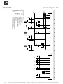
Circuit diagram 1/2 LW 81ASX

16
Subject to change without notice | 83063200fUK – Translation into English of the original German operating manual | ait-deutschland GmbH
L Reg
/1.15
MOT
/1.15
R23
/1.15
N Reg
/1.15
PE
/1.15
12
-X12
L
-X10
6 11
N
P
+-
b2 c4
a1
-F1
HDP
5
A1
A2
-Q1
VD1
1
-X12
A1
A2
-K6
7
28
-X10
-K20
10
-X12
A1
A2
-Q3
VBO
3
P
+-
c4
a1
-F2
NDP
8
-X12
ϑ
-STB
A1
A2
-Q5
ZWE
P
-+
c4
a1
-B10
AEP
9
ϑ
1
-X52
-R4
TRL
2
ϑ
3
-R5
TVL
4
ϑ
5
-R6
THG
6
ϑ
7
-R3
TWA
8 9
29
-X10
-R10
CW
10
30
ϑ
11
-R2
TWE
12
12
/1.4
34
/1.4
56
/1.5
12
/1.12
34
/1.12
56
/1.12
14 11
/1.9
12
/1.7
34
/1.7
56
/1.7
VD1
VBO
B10
Function
Terminal in switch box heat pump
VD1
Q3
Defrosting valve
AEP Defrosting pressostat
X12
-X52
HDP
PE
R6
Encoding resistor, 442 Ohm
Q1
X10
HD
F2
R3
Operating materials
Plug on switch box heat pump (control line)
-X12
TRL
L1
NDP
PE
Safety temperature limiter heating element
VBO
Contactor for auxiliary heating
R2
Flow sensor
STB
R10
Contactor for compressor 1
ASD
K20
Q5
CW
F1
UK817349b
Return sensor
-B10-F2
TWA
Hot gas sensor
If installed: heat source outlet gauge
MOT ZW1
ZW1
R4
rtbl 2
K6 auxiliary relay compressor 1
If installed: heat source input gauge
R5 TVL
1
X52
1
TWE
-F1
TVL
Low-pressure switch
High-pressure switch
N
Legend:
TWE
-K20
ND
THG
Contactor fan
AV
PE
Plug on switch box heat pump (gauge line)
THG
bl 2
TRL
TWA
LW81A/SX
817349
Achim Pfleger 18.05.2010
b ÄM 006/2012
1 2 3 4 5 6 7 8 9 10 11 12 13 14 15 16
1 2 3 4 5 6 7 8 9 10 11 12 13 14 15 16
2/2
2
23.02.2012
ÄM 009/2010a
Achim Pfleger
Blatt-Nr.
Zustand
Änderung
Bearb.
Datum
Name
Bl von Anz
Datum
LW 81ASX Circuit diagram 2/2

17
Subject to change without notice | 83063200fUK – Translation into English of the original German operating manual | ait-deutschland GmbH
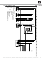
1
-X8
2 PE
1L1
-X9
1N-
1PE
1
2
-Q5
/2.10
-E22
ZW1
3
4
5
6
1N
-X10
N
-X10
1
2
-Q1
/2.4
3
4
M
3
T1
T2
T3
PE
-M1
VD1
5
6
L1
-F6
-C1
13
14
-Q1
/2.4
43
44
-Q1
/2.4
R
RC
L1
S
ON
N
11
12
14
-Q11
-F4
M
1
+10V
0-10V
GND
-F3 -E23
TK
L1 N PE NC
Com
bl
L Reg
/2.1
N Reg
/2.1
R23
/2.1
K21
/2.1
+10V
/2.1
0-10V
/2.1
GND
/2.1
PE
/2.1
Fuse fanF4
2
C1
3
3
1
ZW1
VD1
Operating condenser 55µF for compressor
Contactor for auxiliary heating
1~N/PE/230V/50Hz
1~N/PE/230V/50Hz
3
-M1
E22
E23
5
F3
N
Q5
Operating materials
PE
Compressor 1
L1
2
6
Motor protection fan
M1
Nozzle heating fan
Auxiliary heating
2
1
4
UK817350a
ZW1
Starting current limit
X8
G1
Legend:
2
Terminal in switch box heat pump
Function
1~N/PE/230V/50Hz
1~N/PE/230V/50Hz
X10
Distribution box power supply additional heating
L1/N/PE: Power supply output compressor
4
1
PE
X9
-G1
VD1
1
Distribution box power supply output compressor
Contactor for compressor 1
3
1L1/N/PE: Power supply Aux. heating
Q1
Q11
VENT1 Fan
LW121 A/SX
817350
Achim Pfleger 21.06.2010
- ÄM 012/2011
1 2 3 4 5 6 7 8 9 10 11 12 13 14 15 16
1 2 3 4 5 6 7 8 9 10 11 12 13 14 15 16
1/2
1
29.04.2011
PEP 009/2010-
Achim Pfleger
10X583;
Blatt-Nr.
Zustand
Änderung
Bearb.
Datum
Name
Bl von Anz
Datum
Circuit diagrams 1/2 LW 121ASX

18
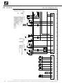
Subject to change without notice | 83063200fUK – Translation into English of the original German operating manual | ait-deutschland GmbH
L Reg
/1.14
R23
/1.14
K21
/1.14
GND
/1.14
0-10V
/1.14
+10V
/1.14
N Reg
/1.14
PE
/1.14
12
-X12
L
-X10
11
12 14
-K3
7
1
-X10
-R50
6
2 3
-R51
11
-X12
N
-X10
P
+-
b2 c4
a1
-F1
HDP
5 1
A1
A2
-Q1
VD1
7
-X12
28
-X10
-K20
10
A1
A2
-K3
2
27
-X10
-K21
3
-X12
P
+-
c4
a1
-F2
NDP
8
ϑ
-STB
A1
A2
-Q5
ZW1
P
-+
c4
a1
-B10
AEP
9
ϑ
1
-X52
-R4
TRL
2
ϑ
3
-R5
TVL
4
ϑ
5
-R6
THG
6
ϑ
7
-R3
TWA
8 9
29
-X7
-R10
CW
10
30
ϑ
11
-R2
TWE
12
12
/1.4
34
/1.4
56
/1.5
12
14
11
2
12
/1.6
34
/1.6
56
/1.7
13 14
/1.7
43 44
/1.8
Time relay bypass compressor 1
-F2
THG
bl
UK817350a
Auxiliary relay, fan activation
2
Low-pressure switch
Plug on switch box heat pump (gauge line)
ND
VEN
R5
CW
If installed: heat source input gauge
Flow sensor
TRL
R6
R10
If installed: heat source outlet gauge
R2
TWA
THG Hot gas sensor
R4
TWE
Return sensor
Encoding resistor, 4870 Ohm
R3
UK817350a
Operating materials
Legend:
Function
Q1
Function
HD
F2
X12
HDP
VD1
Defrosting pressostat
F1
K20
PE
Terminal in switch box heat pump
Legend:
Contactor for compressor 1
VBO
-K20
B10
N
STB Safety temperature limiter heating element
VBO
Contactor for auxiliary heating
VD1
NDP
PE
Defrosting valve
TVL
-X12
Plug on switch box heat pump (control line)
X10
L1
Operating materials
AEP
R50
Q5
-K21
R51
K3
-X52
Bypass compressor 1
1rt
ZW1
Voltage divider 2.49 kohm
High-pressure switch
TRL TWETWATVL
ASD
KT1
K21
MOT
-B10
ZW1
-F1
X52
21bl PE
Voltage divider 7.50 kohm
AV
LW121 A/SX
817350
Achim Pfleger 11.05.2010
a ÄM 012/2011
1 2 3 4 5 6 7 8 9 10 11 12 13 14 15 16
1 2 3 4 5 6 7 8 9 10 11 12 13 14 15 16
2/2
2
29.04.2011
PEP 009/2010-
Achim Pfleger
10X583;
Blatt-Nr.
Zustand
Änderung
Bearb.
Datum
Name
Bl von Anz
Datum
LW 121ASX Circuit diagram 2/2

19
Subject to change without notice | 83063200fUK – Translation into English of the original German operating manual | ait-deutschland GmbH
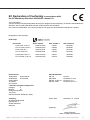
II
A1
ait-deutschland GmbH
Industrie Str. 3
93359 Kasendorf
Germany
15031841
15031841
15029001
100431
100432
100581
100583
100581
100583
Category
LW 81 ASX-LUX 2.0
LW 121 ASX-LUX 2.0
LW 81 ASX-HT 1
LW 121 ASX-HT 1
confirms that the following designated device(s) as designed and marketed by us fulfill the standardized EC
directives, the EC safety standards and the product-specific EC standards.
In the event of modification of the device(s) without our approval, this declaration shall become invalid.
The undersigned
Heat Pump
15029001
15029001
100431LUX02
100432LUX02
LW 90 ARX-LUX 2.0
LW 140 ARX- LUX 2.0
15029001
100581LUX02
100581HT102
100583HT202
Designation of the device(s)
Item number 2
Item number 1
Order number
EN 378
Kasendorf, 14.12.2015
Place, date:
Signature:
* Pressure equipment component
Module
Company:
Jesper Stannow
Head of Heating Development
Unit model
100583LUX02
EC Directives
Standardized EN
EN 349
EN 60529
Designated position:
TÜV-SÜD
Industrie Service GmbH (Nr.:0036)
EN 60335-1/-2-40
EN ISO 13857
EN 61000-3-2/-3-3
EN ISO 12100-1/2
EN 55014-1/-2
EC Declaration of Conformity in accordance with
the EC Machinery Directive 2006/42/EC, Annex II A
*97/23/EG
2011/65/EG
2006/42/EG
2009/125/EG
2006/95/EG
2010/30/EU
2004/108/EG

ait-deutschland GmbH
Industriestraße 3
D-95359 Kasendorf
E info@alpha-innotec.de
W www.alpha-innotec.de
alpha innotec – an ait-deutschland GmbH brand
UK
-
 1
1
-
 2
2
-
 3
3
-
 4
4
-
 5
5
-
 6
6
-
 7
7
-
 8
8
-
 9
9
-
 10
10
-
 11
11
-
 12
12
-
 13
13
-
 14
14
-
 15
15
-
 16
16
-
 17
17
-
 18
18
-
 19
19
-
 20
20


İlgili makaleler
-
Alpha innotec LWAR S El kitabı
-
-
-
-
-
-
-
-
-
