
Installation Guide
Danfoss Icon™ Master Controller 24 V
www.danfoss.com


Content
Installation Guide Danfoss Icon™ Master Controller 24 V .......................................4
Installationsanleitung Danfoss Icon™ Hauptregler 24 V....................................... 14
Manuel d’installation Contrôleur central 24V Danfoss Icon™.................................24
Guida all’installazione Regolatore principale Danfoss Icon™ da 24 V . . . . . . . . . . . . . . . . . . . . . . . . . 34
Installatiehandleiding Danfoss Icon™ hoofdregelaar 24 V .................................... 44
Installationsvejledning Danfoss Icon™ Masterregulator 24 V ................................. 54
Installationshandbok Danfoss Icon™ huvudstyrenhet 24 V................................64
Installasjonsveiledning Danfoss Icon™ hovedstyreenhet 24 V .............................74
Uppsetningarleiðbeiningar Danfoss Icon™ 24 V móðurstöð...............................84
Asennusohje Danfoss Icon™ 24 V -pääsäädin .............................................94
Montavimo žinynas „Danfoss Icon™“ 24 V pagrindinis valdiklis ...........................114
Instrukcja montażu Sterowniknadrzędny Danfoss Icon™ 24V............................124
Kurulum Kılavuzu Danfoss Icon™ Ana Kontrolör 24 V ....................................134
Danfoss Icon™ Master Controller 24 ...............144
Danfoss Icon™ 24 ...................154
EN
DE
FR
IT
NL
DK
SE
NO
IS
FI
CN
LT
PL
TR
UA
RU
Installation Guide Danfoss Icon™ Master Controller 24 V
VIMCG30F | 088N3678 | 3
© Danfoss | FEC | 2019.02

Installation Guide Danfoss Icon™ Master Controller 24 V
Content
Introduction.........................................................................................4
Application..........................................................................................5
Installation ..........................................................................................7
Optional installations................................................................................7
Setting up the system ...............................................................................8
Removing units from a Danfoss Icon™ Master Controller 24V system..................................8
Connecting more Danfoss Icon™ Master Controllers in a system . . . . . . . . . . . . . . . . . . . . . . . . . . . . . . . . . . . . . .9
Test procedures for multiple Danfoss Icon™ Controllers in a system ...................................9
Slave type denition...............................................................................10
Reset or replace a Danfoss Icon™ Master Controller 24V ............................................10
Trouble shooting ..................................................................................10
Hydraulic balance .................................................................................11
Add-on Modules ..................................................................................12
Technical data.....................................................................................12
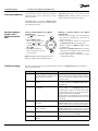
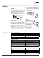
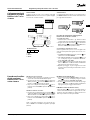
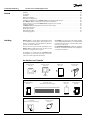
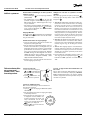
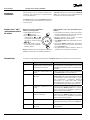
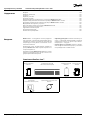
Introduction
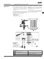
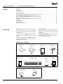
Danfoss Icon™ is a modular heating system for
individual room control. It can be congured as
a wired or wireless system or as a combination, if
required.
The center of the system is the Danfoss Icon™
Master Controller 24V, which congures and ties
the system together.
Installation and set-up of the Danfoss Icon™ Master
Controller 24V is easy and described in the ncluded
materials:
• The Quick Guide shows the most common
installation with step-by-step illustrations, wired
installation on one side and wireless on the other.
• The Installation Guide describes the User
Interface, installation in details and set-up in
more complex systems.
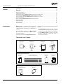
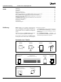
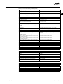
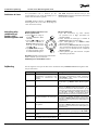
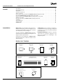
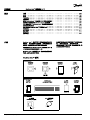
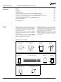
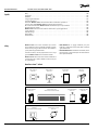
The Danfoss Icon™ family
Wireless system components
Wireless Display
088U1081
Wireless Display
088U1082
Infrared
Radio Module
088U1103
Repeater
088U1102
Common system components
Expansion Module
088U1100
Master Controller 24V
088U107x (multiple versions)
App Module
088U1101
Dew Point Sensor
088U0251
24V system components
24V Display
088U105x (multiple versions)
24V
47 k Floor Sensor
088U1110
4 | © Danfoss | FEC | 2019.02
VIMCG30F | 088N3678

EN
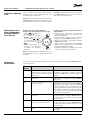
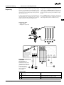
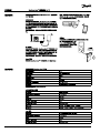
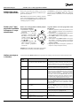
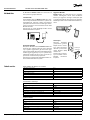
Installation Guide Danfoss Icon™ Master Controller 24 V
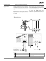
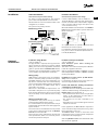
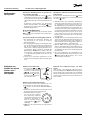
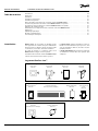
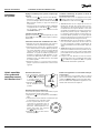
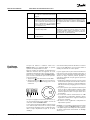
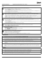
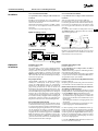
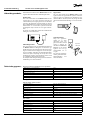
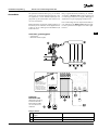
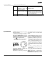
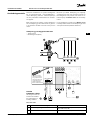
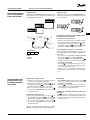
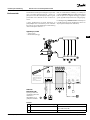
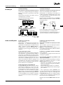
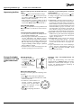
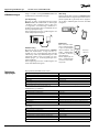
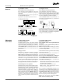
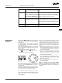
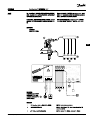
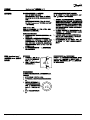
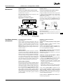
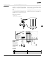
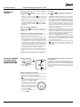
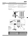
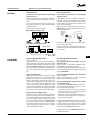
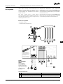
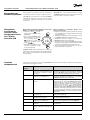
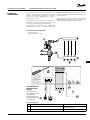
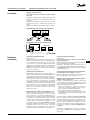
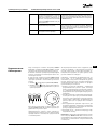
Upon rst installation the system is congured as
a standard oor heating system. In this application
the circulation pump output and the potential free
relay are both activated when there is a heat de-
mand.
Both the boiler relay and the pump output has a
delay of 180 seconds in this application to ensure
there is ow through the circuits before the boiler
is activated.
The use of mixing shunt, connection of circulation
pump to Danfoss Icon™ Master Controller 24V and
use of boiler relay is optional, depending on appli-
cation and available components.
To congure the Danfoss Icon™ Master
Controller 24V system for other applications an
Expansion Module (code no. 088U1100) is required.
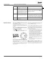
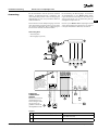
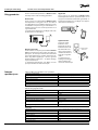
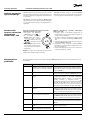
Application
Application, Basic
• 2-pipe system
• Mixing shunt (optional)
Parts list
1 1 pc. Danfoss FHM-Cx mixing shunt (optional) Part no. 088U0093/0094/0096
2 1 set Danfoss Manifold Part no. 088U05xx (FHF), 088U06xx (BasicPlus) or
088U07xx (SSM)
3 x pcs. TWA-A 24 V thermal actuators Part no. 088H3110 (NC), 088H3111 (NO)
O
K
M1
M
M2
M3
M4
M5
LN
LN
APP
230 V
Actuator outputs - 24 V
App
Module
Link
Master
Brown
Blue
Green/Yellow
PWR1 PWR2 RELAY
Radio
Module
Opening of expansion
slot and wiring of
terminals below the
expansion slot shall
only be performed by
a trained electrician.
Risk of electric shock
RISK OF ELECTRIC SHOCK!
Removing lid and installing
230V wires should only
be preformed by a
trained professional.
VIMCG30F | 088N3678 | 5
© Danfoss | FEC | 2019.02

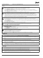
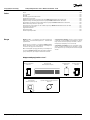
Installation Guide Danfoss Icon™ Master Controller 24 V
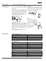
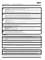
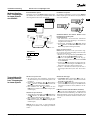
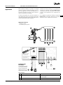
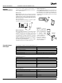
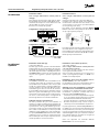
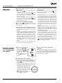
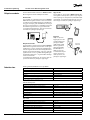
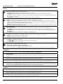
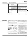
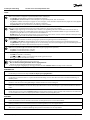
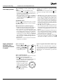
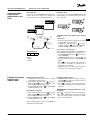
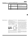
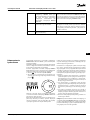
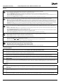
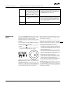
Keys
1. Installer key
Used by the installer when setting up the system (used during installation).
• Select INSTALL for installing and conguring the system.
• Select UNINSTALL for replacing or removing a system component, e.g. a thermostat.
• Select TEST for nalizing the installation and to run one of three test types, either: Network test, Application test or Flow test
(i.e. ushing of system)
• Select RUN when all system devices are installed and a TEST is nished.
2. Mode key
Used for choosing the desired control behavior of the entire system (set once for the entire system).
• PWM+: Type of regulation designed to minimize overheating by dividing the heat demand into smaller bits (= duty cycles). The
length of a duty cycle varies depending on the chosen heat emitter. PWM+ also features auto balancing of ow to the dierent
rooms, which improves the heating comfort.
• On/O: A simple hysteresis control, which turns on the heat when the temperature is below the desired room temperature.
The heat will not be turned o until the desired room temperature is reached.
3. Heat emitter key
Denes which heat emitter is used on the output (optimized control performance for each heat emitter type).
• Select SLOW for oor construction with >50 mm concrete over pipes (typically no heat distribution panels used).
• Select MEDIUM for oor or wall construction with <50 mm concrete over pipes (typically pipes laid onto heat distribution
panels).
• Select FAST for radiator or convector (supplied from a manifold).
4.
M
Actuator type selector key
Used to dene which kind of 24 V actuator is used (set once for the entire system).
• Select NC for normally closed (typically used).
• Select NO for normally open (rarely used).
5. Main user interface
• Press OK to conrm a setting.
• Press or to change a parameter value or toggle through menus.
• Use to go one step backwards in a menu.
6. Output selector keys
Used for assigning actuator outputs to a thermostat.
• Connect only one actuator wire per output terminal.
• Assign as many outputs as you want to a thermostat.
Depending on Danfoss Icon™ Master Controller model, you will have 10 or 15 outputs available.
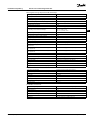
Cable terminals
7. Upper terminal row
For connection of 24 V thermal actuators max. one actuator per output terminal.
8. Lower terminal row
For connection of 24 V thermostats in a wired system, or for additional 24 V wired thermostats in a wireless system.
9. Upper cable strain relief bar
Installed as nal step of wiring, tighten screws to assure wire retention.
10. Lower cable strain relief bar
Clicks over thermostat cables to hold them in place. Top of this part also acts as cable holder for actuator cables.
11. Removable lid
Covers access to the 230 V section of Danfoss Icon™ Master Controller 24V. Remove the screw and slide out to access 230 V termi-
nals. This part can be replaced with the Expansion Module, if special applications are necessary.
Connectors
12. Radio Module connector (RJ 45)
Connect the Radio Module to this connector via cat. 5 patch cable (supplied with the Radio Module).
13. App Module connector (RJ 45)
Connect the App Module to this connector via cat. 5 patch cable (supplied with the APP Module).
14. 3-pole connector – for linking together multiple Master Controllers in a 24V system.
Only used in wired systems! Loose 3-pole male connector supplied with the product.
6 | © Danfoss | FEC | 2019.02
VIMCG30F | 088N3678

EN
Installation Guide Danfoss Icon™ Master Controller 24 V
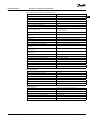
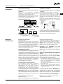
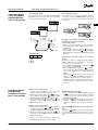
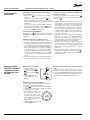
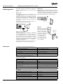
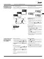
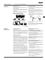
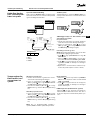
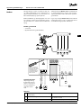
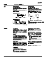
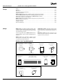
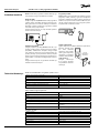
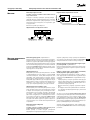
Installation
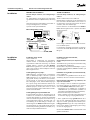
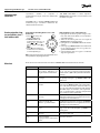
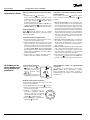
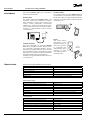
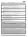
If wired installation
Note! Disconnect power before wiring!
For wiring of wired thermostats and actuators,
please refer to the Quick Guide sections B and C.
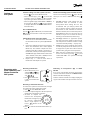
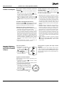
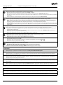
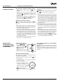
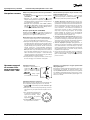
24V Thermostats can be wired either in BUS or Star
conguration, see below.
The system is not polarity sensitive.
If BUS wiring (serial)
If Star wiring (parallel)
ABNTC
2
THERMOSTATS
ABNTC
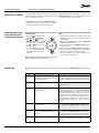
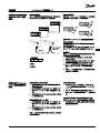
If wireless installation
Note! Disconnect power before wiring!
Connect a Radio Module, code no. 088U1103.
The Radio Module is required, when wireless ther-
mostats are installed. The radio module is supplied
with a 2m patch cable. A longer cable (max. 15m)
can be used if necessary.
One Radio Module must be tted to each Danfoss
Icon™ Master Controller 24V in systems with more
Master Controllers.
088U1103
As a special feature, it is possible to include wired
thermostats in a wireless system.
For installation of wireless thermostats and actua-
tors, please refer to the Wireless Quick Guide sec-
tions B2, B3, B4 and C1.
Optional
installations
Installation of App Module,
code no. 088U1101
The App Module is required, when app function-
ality is wanted. For inclusion in a wireless network
(Wi-Fi), please refer to the App Module installation
guide. In systems with more Danfoss Icon™ Master
Controllers only one App Module is required, and it
can be added to any of the Master Controllers.
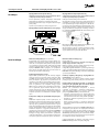
Wiring a pump
PWR1 output is intended for usage in installations
where a circulation pump is present in the system.
The PWR1 output has a live 230 V output (max. 100
W), which is activated when heat is demanded by
at least one thermostat. When no heat is demanded
from any thermostat the PWR1 output will be
turned o to save energy.
When heat is demanded the output will be acti-
vated with a delay of 180 sec. to prevent the pump
from running without being able to generate ow
due to the delay on the actuators in the heating
circuits.
Wiring a potential free relay
A potential free relay can be used e.g. to activate
heat demand/production from a boiler.
It is recommended to use the potential free relay as
heat demand signal for all boilers with appropriate
inputs available.
For boilers with 0-10 V modulation it is not possible
to use the heat demand signal from the Danfoss
Icon™ Master Controller 24V.
Please note that some combi-boilers may have hot
water prioritization, which can cause heat produc-
tion of the system to be delayed.
Installation of Expansion Module,
code no. 088U1100.
Note! Disconnect power before inserting the
Expansion Module.
Slide of the cover and insert the Expansion Module.
Follow the supplied instructions.
Note! If an Expansion Module is added to a system
with multiple Master Controllers, it must be installed
on the System Master.
Installation of a Floor Sensor (if 24V thermo-
stat), code no. 088U1110.
For installation of a oor sensor, please refer to in-
structions supplied with the thermostat.
Rooms with both oor heating and radiators
controlled by one thermostat.
It is possible to have a mixed application with both
radiators and oor heating controlled by the same
Danfoss Icon™ room thermostat, if
• The thermostat has a oor sensor set up for “dual
mode“ on the thermostat (set “DU” mode in
installer menu on thermostat).
• The radiator has it’s ow controlled by an
actuator.
• Remember to set correct emitter type for relevant
outputs in said room.
In this application, the oor sensor is only used to
assure a min. oor temperature (if necessary, a max.
oor temperature can be set).
The built-in sensor is used to control the room
temperature by the assigned radiator output (the
fastest of the two output types).
Note! Only Danfoss Icon™ room thermostats with
oor sensor are supported.
VIMCG30F | 088N3678 | 7
© Danfoss | FEC | 2019.02

Installation Guide Danfoss Icon™ Master Controller 24 V
Common settings for entire system (set once)
• Use the key to choose INSTALL mode.
• Choose actuator type, press
M
to choose NC
(normally closed is default) or NO (normally
open). The type will be marked on the actuator.
• Choose regulation type, either PWM+ or ON/OFF,
by pressing the Mode key (see description
in chapter “Overview of Danfoss Icon™ Master
Controller 24V”).
Choose INSTALL mode
Use the key (Quick Guide D2) and conrm with
OK. The Master Controller is now ready to include
thermostats.
Include thermostats and assign outputs
1. Touch the screen of the thermostat to include
the thermostat into the system (Quick Guide
D4).
2. Choose the output(s) on the master controller,
which the thermostat must control (Quick
Guide D5). The available outputs will have
a ashing LED. Once output is assigned to a
thermostat, it will be permanently lit. Conrm
with OK. Note! Type of heat emitter used in room
“Slow / medium / fast” (slow = default) must be
choosen before conrming with OK.
3. Repeat step 1 – 2 for all rooms until all
thermostats and outputs are paired.
Final test and starting system in normal run mode
Choose “test” mode by pressing key. In the test
menu you can choose 3 dierent tests using
keys:
1. Test Net. Performs a full network test. The
thermostats must be mounted in their
nal position when starting the test. We
recommend that you always perform this
test in a wireless system, to make sure that all
thermostats can still communicate with the
Master Controller, when in their nal position.
(Quick Guide E7). This test can run for up to 30
minutes, but you can accelerate the test by
touching each thermostat (to wake it up).
2. Test App. Performs an application specic
test if the expansion module is tted. Test all
sub-components and allows installer to verify
correct functionality visually — step by step.
3. Test Flo. Force opens all outputs and activates
circulation pump. Run for 30 minutes, but can
be stopped at any time. Use to bleed air from
system before going into normal operation.
4. When you have conducted the needed tests,
choose “run” mode by pressing key and
conrm with “OK” – the system is now fully
operational.
Setting up
the system
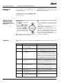
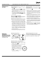
Removing units
from a Danfoss Icon™
Master Controller
24V system
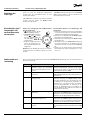
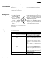
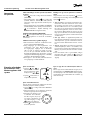
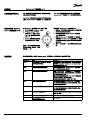
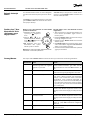
Removing a thermostat
1. On the thermostat, press
and hold and for 3
seconds until the display
says .
2. Press . The thermostat
is now removed from the
system.
Removing an unresponsive App or Radio
Module
If an app or radio module becomes unresponsive
an alarm code will be shown in the Danfoss Icon™
Master Controller 24V display.
Find the defective module and simply unplug the
app or radio module and replace it with a new one.
OK
Removing a defective thermostat
If a unit in the system becomes defective, it might
be required to remove it from the system.
1. Press to select UNINSTALL mode.
2. Select the output assigned to the unresponsive
thermostat on the Master Controller.
3. All LED’s on outputs con-
nected to the unresponsive
thermostat will light up and
be selected automatically
when a single output is se-
lected. ashes on the
display.
4. Press to remove the thermostat from the sys-
tem.
8 | © Danfoss | FEC | 2019.02
VIMCG30F | 088N3678

EN
Installation Guide Danfoss Icon™ Master Controller 24 V
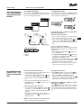
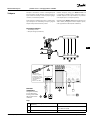
Connecting more
Danfoss Icon™
Master Controllers in
a system
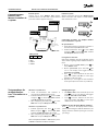
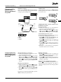
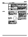
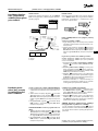
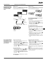
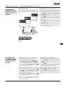
If wired system
Connect up to three Danfoss Icon™ Master
Controller 24V to each other with a 4-wire twisted
pairs cable and the supplied connector.
Cable pin out
1 2 3
1. GND
2. COM A
3. COM B
If wireless system
Wireless connection of up to three Danfoss Icon™
Master Controllers 24V requires a Radio Module
with each Master / Slave.
Connecting procedure for multiple Danfoss
Icon™ Controllers in a system
On System Master
1. Install all thermostats and thermal actuators as
described in the Quick Guide D2 to D6.
2. Perform network test. Press to select TEST
and press to choose NET TEST. Conrm
witk OK (Quick Guide E7 and E8).
Pairing Master and Slave
Note! Slave Controllers must be assigned as System
Slaves before assigning outputs and thermostats to
them.
1. On the selected system master, press to
select INSTALL mode.
2. On the system slave, press and hold for
1,5 sec. The display now toggles between
SLA TYPA and SLA TYPB.
3. Press to choose between the two slave
types and conrm with OK. See “Slave type
denition” on the next page.
4. Repeat step 1 – 3 to assign a 2
nd
Slave Controller
to the system (max. two slaves are permitted).
NET TEST on System Slave
1. Install all thermostats and actuators as
described in the Quick Guide D2 to D6.
2. Perform Network test. Press to select TEST
and press to choose NET TEST. Conrm
with OK (Quick Guide E7 and E8).
3. After completing the TEST press to select
RUN mode and press OK (Quick Guide E9).
APP TEST on System Master
1. Perform application test. Press to select
TEST and press to choose APP TEST.
Conrm with OK (Quick Guide E7 and E8).
2. After completing the TEST press to select
RUN mode and press OK (Quick Guide E9).
Note! If an Expansion Module is added to the system,
it must be installed on the Master Controller.
Changing Slave type
1. On Danfoss Icon™ Slave Controller press and
hold for 1.5 sec. The display now toggles
between SLA TYPA and SLA TYPB.
2. Press to choose between the two slave
types and conrm with OK. See “Slave type
denition” for more information.
LINK test on Slave (between Master and Slave)
Press for 1.5 sec. The display shows inclusion
pattern while making the LINK test. When done, the
display shows the number of packages recieved in
percentage.
Test procedures for
multiple Danfoss
Icon™ Controllers in a
system
VIMCG30F | 088N3678 | 9
© Danfoss | FEC | 2019.02
4 (2 x twisted pairs)
Max. 3 x Master
Controllers in one
system.

Installation Guide Danfoss Icon™ Master Controller 24 V
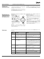
Reset or replace a
Danfoss Icon™
Master Controller
24V
Factory resetting of Danfoss Icon™ Master
Controller 24V
1. Press to select UNINSTALL
mode.
2. On the Danfoss Icon™
Master Controller 24V, press
and hold and for 3
seconds until the display says
.
3. Press OK. All settings on
Master Controller are reset to
factory settings.
Note! Individual room thermostats must be reset
locally, see chapter “Removing a thermostat”.
Replacing a defective Danfoss Icon™ Master
Controller 24V
1. Remove all thermostats and other units from
the system by following the procedure for
factory resetting.
2. Make a note of how all wires are connected to
the Danfoss Icon™ Master Controller 24V.
3. Remove wiring to Danfoss Icon™ Master
Controller 24V.
4. Mount the new Danfoss Icon™ Master Controller
24V and reconnect all wires to the same position
as on the replaced Master Controller.
5. Set up system again as described in chapter
“Setting up the system”.
OK
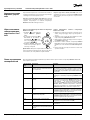
Trouble shooting
If an error is detected, an alarm code will be displayed either on the Danfoss Icon™ Master Controller
24V or on the thermostat.
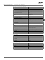
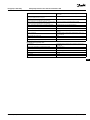
Alarm code Problem Solution
Er03 You have set-up a cooling applica-
tion that requires a reference room
thermostat to be appointed.
Please go to the thermostat in the desired
reference room and enter the thermostat installer
menu. Set thermostat to ON in ME.6 ”reference
room thermostat”.
Er05 Communication lost to Radio
Module.
Please check that the cable is properly connected
in the Radio Module and Danfoss Icon™ Master
Controller 24V.
Er06 Communication lost to room
thermostat.
Identify the room thermostat by looking at the
ashing outputs on the Danfoss Icon™ Master
Controller 24V, or look at the thermostats. Wake
up thermostat, then press on the thermostat.
Failing thermostat will say “NET ERR”.
Replace batteries on room thermostat and perform
a network test (activate NET TEST in menu on room
thermostat).
Er07 Communication lost to Slave
Controller.
If wireless, check Radio Module connection to
Danfoss Icon™ Master Controller 24V. If wired
system, check the wire connecting the controllers.
Er08 Communication lost from Slave to
Master Controller.
If wireless, check Radio Module connection to
Danfoss Icon™ Master Controller 24V. If wired
system, check the wire connecting the controllers.
Er10 Communication lost to Repeater. Check that the repeater is plugged into outlet / has
not been removed and outlet is ON.
Er11 Communication lost to Expansion
Module.
Check that Expansion Module is slidded fully into
place.
The potential free relay is activated on all Master
Controllers when heat is demanded on either
Master Controller.
SLA TYPA: Pump is activated on Danfoss Icon™
Master Controller 24V when heat is demanded on
either Master or Slave(s).
SLA TYPB: Pump relay is only activated on the
Danfoss Icon™ Controller 24V to which the
thermostat with heat demand is assigned.
Slave type denition
10 | © Danfoss | FEC | 2019.02
VIMCG30F | 088N3678

EN
Installation Guide Danfoss Icon™ Master Controller 24 V
Er12 Actuator defective.
The defective actuator output is
ashing.
Replace actuator.
Er14 A Danfoss Icon™ Master Controller
cannot be included as (become)
a Slave Controller because one or
more room thermostats, repeaters
or Danfoss Icon™ Master Controller
24V have already been included.
This Danfoss Icon™ Master Controller 24V has to
be factory reset to become a Slave Controller. (See
description in chapter ”Reset or replace a Danfoss
Icon™ Master Controller).
Er16: This application requires a specic
actuator output to be available.
You have already assigned this output to a
room thermostat, or the output has not yet had
an actuator tted. Please remove output from
thermostat, it must be available to the application
chosen (or t actuator - if this was not yet done)
Er17: External PT1000 sensor not tted,
or defective.
Check sensor and replace if necessary.
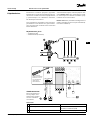
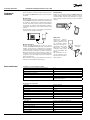
Hydraulic balance
When using the Danfoss Icon™ Master Controller
24V with PWM+ regulation, the system will auto-
matically balance the circuits.
In heating systems with extreme dierences in cir-
cuit lengths, the automatic balancing might not be
adequate.
In these cases the Danfoss Icon™ Master Controller
24V can help you determine which circuits that are
struggling to get enough ow:
1. Press to select RUN mode.
2. Press an button to see the average duty cycle
in percentage for the selected circuit.
OK
When pressing the output button the average duty
cycle is shown in the display of the Danfoss Icon™
Master Controller 24V.
The duty cycle is shown as the amount of time in
% that the actuator is open during active heating
periods and only when in heating mode as an av-
erage over time.
This feature can help determine if one or more
rooms have diculty receiving enough ow or ef-
fect to reach optimal comfort.
The room with the highest duty cycles is the one
that calls for the highest ow. If this room has prob-
lems reaching the desired room setpoint temper-
ature, the following steps can help give this room
more ow/heating capacity:
1. Increase the ow for the room with the high-
est duty cycle, using the pre-setting valve
on the manifold -> set to maximum ow on
pre-setting valves for this room’s outputs.
2. If the room with the highest duty cycle is al-
ready at maximum ow, instead reduce the
ow for the outputs that show the lowest duty
cycle (these do not need as much ow).
3. If none of the above is enough to reach the
desired room temperature, increase the total
ow, by setting a higher ow on the circula-
tion pump.
4. As a last resort increase the supply tempera-
ture into the system.
Note! By installing an Expansion Module in the
Danfoss Icon™ Master Controller 24V the system
will be able to automatically adjust the supply
temperature according to heat demand in the rooms.
VIMCG30F | 088N3678 | 11
© Danfoss | FEC | 2019.02

Installation Guide Danfoss Icon™ Master Controller 24 V
Add-on Modules
You can extend the functionalities of Danfoss
Icon™ Master Controller 24V with Add-on Modules.
Radio Module
By adding a Radio Module the Danfoss Icon™
Master Controller 24V is converted from a wired
to a wireless solution. The wireless solution
provides a higher degree of exibility in placing
the thermostats. In a wireless system, each Master
Controller must have it’s own Radio Module.
For more information, see the installation guide
supplied with the Radio Module.
Expansion Module
By installing an Expansion Module the Danfoss
Icon™ Master Controller 24V can be used with more
applications such as electronic mixing shunt control
or in cooling applications. Just install the Expansion
Module, choose the appropriate application
from a list and make the wiring according to the
description – then the conguration is made
automatically.
For more information, see the installation guide
supplied with the Expansion Module.
App Module
By adding an App Module to Danfoss Icon™ Master
Controller 24V the system enables app support
for control via smart phones (supports IOS and
Android). For more information, see the installation
guide supplied with the App Module.
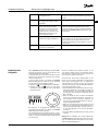
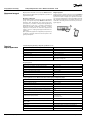
Repeater
Add a repeater in
large buildings where
added wireless range
is needed. Set Master
Controller to INSTALL
mode to add a
repeater.
For more information,
see the installation
guide supplied with
the Repeater.
Repeater
088U1102
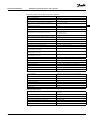
Technical data
Common characteristics, all Danfoss Icon™-products
Temperature for the ball pressure test 75 °C
Control polution degree Degree 2, normal household environment
Software class Class A
Rated impulse voltage 4 kV
Operating time Permanently connected
Temperature range, storage and transportation -20 °C to + 65 °C
Dispossal instructions The product must be disposed as electronic waste.
Full data sheet available at www.danfoss.com
Radio Module & Repeater
Purpose of control Transmitting and receiving device
Ambient temperature range, continious use 0 °C to + 40 °C
Frequency 869 MHz
Transmission power <2,5 mW
Encapsulation (IP Class) IP 20
Conformity declared acc. to following directives RED, RoHS, WEEE
Protection class Radio: Class III Construction Repeater: Class II Construction
Supply voltage Radio: 5 V DC Repeater: 230 V AC 50/60 Hz
App Module
Purpose of control Wi-Fi transmitting and receiving device, incl. Bluetooth
Ambient temperature range, continious use 0 °C to + 40 °C
Frequency 2,4 GHz
Encapsulation (IP Class) IP 20
Conformity declared acc. to following directives RED, RoHS, WEEE
Protection class Radio: Class III
Supply voltage 5 V DC
12 | © Danfoss | FEC | 2019.02
VIMCG30F | 088N3678

EN
Installation Guide Danfoss Icon™ Master Controller 24 V
Master Controller 24V and Expansion Module (optional)
Supply voltage 220-240 V AC
Supply frequency 50/60 Hz
Output voltage, actuators 24 V DC
Max. power consumption per actuator output 2 W
Number of actuator outputs (1 actuator per output terminal) 10 or 15 depending on type
Output voltage, thermostats 24 V DC
Stand-by consumption per thermostat 0,2 W
Max. number of thermostats 10 or 15 depending on type
Max. length of wire from master controller to a 24 V thermostat
(depends on cable type used)
If 2x2x0,6 mm² STP/UTP: 100 m
If 2x0,5 mm²: 150 m
If > 2x0,75 mm²: 200 m
Stand-by consumption, Master Controller < 2 W
Max. power consumption, excluding use of PWR 1 and PWR 2
outputs
< 50 W
Internal protection (fuse, non-replacable) 2,5 A
Output “Relay” Micro-disconnection (Type 1.B action), Max. 2 A load
Actuator outputs, type Electronic disconnection (Type 1.Y action)
Output “PWR 1”, type and rated max. output Micro-interruption (Type 1.C action)
Output “PWR 2”, type and rated max. output Type: Permanent output, Always live 230 V, Max. 50W
Output “PWR 3” (optional, on Expansion module — used for dew
point sensor)
24 V DC, max. 1 W
Input “1” (optional, on Expansion module — use varies acc. to
application chosen)
Ext. switch input (internal 24 V pull-up)
Input “2” (optional, on Expansion module — use varies acc. to
application chosen)
Ext. switch input (internal 24 V pull-up)
Input “3”, sensor input (optional, on Expansion module) External sensor, PT 1000 (Danfoss ESM 11)
Dimensions W: 370 mm, H: 100 mm, D: 53 mm
Conformity declared acc. to following directives LVD, EMC, RoHS and WEEE
Purpose of control Individual electronic room temperature control
Method of providing earthing Factory tted power cord, incl. PE-conductor
Encapsulation (IP Class) IP 20
Protection class Class I
Ambient temperature range, continious use 0 °C to + 50 °C
Wireless Thermostat
Purpose of control Room thermostat for room temperature control
Ambient temperature range, continious use 0 °C to + 40 °C
Frequency 869 MHz
Transmission power <2,5 mW
Encapsulation (IP Class) IP 21
Supply voltage 2 x 1,5 V AA-Alkaline batteries
Conformity declared acc. to following directives RED, RoHS, WEEE
Protection class Class III
24V Wired Thermostat
Purpose of control Room thermostat for room temperature control
Ambient temperature range, continious use 0 °C to + 40 °C
Encapsulation (IP Class) IP 21
Supply voltage 24 V DC
Conformity declared acc. to following directives EMC, RoHS, WEEE
Protection class Class III
External sensor NTC type, 47 k @ 25 °C (Optional, 088U1110)
VIMCG30F | 088N3678 | 13
© Danfoss | FEC | 2019.02

Installationsanleitung Danfoss Icon™ Hauptregler 24 V
Einführung .............................................................................................. 14
Anwendung.............................................................................................15
Installation ..............................................................................................17
Optionale Installationen .................................................................................17
Konguration des Systems...............................................................................18
Entfernen von Geräten aus einem Danfoss Icon™ Hauptregler 24V System ................................18
Mehrere Danfoss Icon™ Hauptregler in einem System anschließen .......................................19
Testverfahren für mehrere Danfoss Icon™ Hauptregler in einem System ..................................19
Denition des Slave-Typs ................................................................................ 20
Einen Danfoss Icon™ Hauptregler 24V zurücksetzen oder austauschen....................................20
Fehlersuche und -behebung .............................................................................20
Hydraulischer Ausgleich .................................................................................21
Zusatzmodule...........................................................................................22
Technische Angaben ....................................................................................22
Inhalt
Einführung
Danfoss Icon™ ist ein modulares Heizungssystem
für die individuelle Raumtemperaturregelung. Es
kann als verdrahtetes oder drahtloses System oder
gegebenenfalls auch als Kombination konguriert
werden.
Kern des Systems ist der Danfoss Icon™ Hauptregler
24V, der das System konguriert und verknüpft.
Die Installation und Einrichtung des Danfoss Icon™
Hauptreglers 24V ist einfach und in den beigefügten
Materialien beschrieben:
• Die Kurzanleitung zeigt die geläugste Installation
mit Schritt-für-Schritt-Abbildungen: verdrahtete
Installation auf einer Seite und drahtlos auf der
anderen Seite.
• Die Installationsanleitung beschreibt die
Benutzeroberäche, die detaillierte Installation und
die Einrichtung in komplexeren Systemen.
Die Danfoss Icon™ Familie
Drahtlose Systemkomponenten
Funkdisplay
088U1081
Funkdisplay
088U1082
Infrarot
Funkmodul
088U1103
Verstärker
088U1102
Gemeinsame Systemkomponenten
Erweiterungsmodul
088U1100
Hauptregler 24V
088U107x (mehrere Versionen)
App-Modul
088U1101
Taupunktfühler
088U0251
24V Systemkomponenten
24 V, Version mit Display
088U105x (mehrere Versionen)
24V
47 k Bodenfühler
088U1110
14 | © Danfoss | FEC | 2019.02
VIMCG30F | 088N3678

Installationsanleitung Danfoss Icon™ Hauptregler 24 V
DE
O
K
M1
M
M2
M3
M4
M5
LN
LN
APP
230 V
Actuator outputs - 24 V
App
Module
Link
Master
Brown
Blue
Green/Yellow
PWR1 PWR2 RELAY
Radio
Module
Bei der Erstinstallation wird das System als standard-
mäßiges Bodenheizungssystem konguriert. Bei
dieser Anwendung werden sowohl der Ausgang der
Umwälzpumpe als auch das potentialfreie Relais bei
Heizbedarf aktiviert.
Das Kesselrelais und der Pumpenausgang weisen bei
dieser Anwendung eine Verzögerung von 180 Sekun-
den auf, um sicherzustellen, dass vor Aktivierung des
Kessels Ströme durch die Stromkreise ießen.
Die Verwendung der Mischergruppe, der Anschluss
der Umwälzpumpe an den Danfoss Icon™ Haupt-
regler 24V und die Verwendung des Kesselrelais sind
optional und hängen von der Anwendung und den
verfügbaren Komponenten ab.
Um das System Danfoss Icon™ Hauptregler 24V für
andere Anwendungen zu kongurieren, ist ein Erwei-
terungsmodul (Artikelnr. 088U1100) erforderlich.
Anwendung
Anwendung, Basic
• Zweirohrsystem
• Mischergruppe (optional)
Teileliste
1 1 St. Danfoss FHM-Cx Mischergruppe (optional) Best.-Nr. 088U0093/0094/0096
2 1 Satz Danfoss-Verteiler Best.-Nr. 088U05xx (FHF), 088U06xx (BasicPlus)
oder 088U07xx (SSM)
3 x Stk. TWA-A 24 V Thermische Stellantriebe Best.-Nr. 088H3110 (NC), 088H3111 (NO)
VIMCG30F | 088N3678 | 15
© Danfoss | FEC | 2019.02
Das Önen des Erweite-
rungssteckplatzes und die
Verdrahtung der Klem-
men unter dem Erweite-
rungssteckplatz darf nur
von einer Elektrofachkraft
durchgeführt werden.
Es besteht Stromschlag
Gefahr.
ES BESTEHT
STROMSCHLAG
GEFAHR!
Entfernen des Deckels
und Installieren von
230V-Leitungen sollte
nur von einer aus-
gebildeten Fachkraft
durchgeführt werden.

Installationsanleitung Danfoss Icon™ Hauptregler 24 V
Tasten
1. Installateurstaste
Wird bei Konguration des Systems (während der Installation) durch den Installateur betätigt.
• INSTALLIEREN auswählen, um das System zu installieren und zu kongurieren.
• DEINSTALLIEREN auswählen, um eine Systemkomponente wie beispielsweise einen Thermostat auszutauschen oder zu entfernen.
• TEST auswählen, um die Installation abzuschließen und eine von drei Testarten durchzuführen: Netzwerktest, Anwendungstest oder
Flusstest (d. h. Spülen des Systems)
• AUSFÜHREN wählen, wenn alle Systemgeräte installiert sind und ein TEST abgeschlossen ist.
2. Modus-Taste
Dient der Auswahl des gewünschten Steuerungsverhaltens des gesamten Systems (wird einmal für das gesamte System eingestellt).
• PWM+: Regelungsart zur Minimierung einer Überhitzung durch Aufteilen des Heizbedarfs in kleinere Abschnitte (= Arbeitszyklen). Die
Länge eines Arbeitszyklus hängt von dem gewählten Heizelement ab. PWM+ verfügt außerdem über einen automatischen Abgleich
des Durchusses zu den verschiedenen Räumen, was zur Verbesserung des Heizkomforts beiträgt.
• On/O: Eine einfache Hysteresesteuerung, welche die Heizung einschaltet, sobald die Temperatur unter der gewünschten Raumtempe-
ratur liegt. Die Heizung wird erst ausgestellt, wenn die gewünschte Raumtemperatur erreicht ist.
3. Heizelement-Taste
Legt fest, welches Heizelement am Ausgang verwendet wird (optimierte Regelleistung für jeden Heizelemententyp).
• LANGSAM für Fußbodenkonstruktionen mit >50 mm Beton über den Rohren wählen (in der Regel werden keine Elemente zur Wärme-
verteilung verwendet).
• MITTEL für Fußboden- oder Wandkonstruktionen mit <50 mm Beton über den Rohren wählen (die Rohre sind in der Regel auf Elemen-
ten zur Wärmeverteilung verlegt).
• SCHNELL für Heizkörper oder Konvektor (über einen Verteiler gespeist) wählen.
4.
M
Auswahltaste Typ Stellantrieb
Dient der Festlegung, welche Art von 24V-Stellantrieb verwendet wird (wird einmal für das gesamte System eingestellt).
• NC für normal geschlossen wählen (in der Regel verwendet).
• NO für normal oen wählen (selten verwendet).
5. Hauptbenutzeroberäche
• OK drücken, um eine Einstellung zu bestätigen.
• oder drücken, um einen Parameterwert zu ändern oder zwischen den einzelnen Menüs umzuschalten.
• Mit einen Schritt rückwärts im Menü gehen.
6. Ausgangswahltasten
Dient der Zuweisung von Stellantriebausgängen zu einem Thermostat.
• Nur ein Stellantriebskabel je Ausgangsklemme anschließen.
• Einem Thermostat können beliebig viele Ausgänge zugewiesen werden.
Je nach Modell des Danfoss Icon™ Hauptreglers sind 10 oder 15 Ausgänge verfügbar.
Kabelklemmen
7. Obere Klemmenleiste
Für den Anschluss von thermischen Stellantrieben 24 V max. einen Stellantrieb je Ausgangsklemme verwenden.
8. Untere Klemmenleiste
Für den Anschluss von 24 V-Thermostaten in einem verdrahteten System oder zusätzliche verdrahtete 24 V-Thermostate in einem draht-
losen System.
9. Obere Leiste zur Kabel-Zugentlastung
Als letzter Schritt der Verdrahtung installiert. Schrauben festziehen, um die Kabelsicherung sicherzustellen.
10. Untere Leiste zur Kabel-Zugentlastung
Rastet über den Thermostatkabeln ein, um diese an Ort und Stelle zu halten. Der obere Abschnitt dieses Teils dient außerdem als Kabel-
halterung für Stellantriebskabel.
11. Abnehmbarer Deckel
Deckt den Zugang zu dem 230V-Abschnitt des Danfoss Icon™ Hauptreglers 24V ab. Für den Zugri auf die 230 V-Klemmen Schraube
entfernen und herausschieben. Dieses Teil kann durch das Erweiterungsmodul ersetzt werden, wenn besondere Anwendungen erforder-
lich sind.
Anschlüsse
12. Funkmodulanschluss (RJ 45)
Das Funkmodul mit einem Patchkabel der Kat. 5 (im Lieferumfang des Funkmoduls enthalten) an diesen Anschluss anschließen.
13. App-Modulanschluss (RJ 45)
Das App-Modul mit einem Patchkabel der Kat. 5 (im Lieferumfang des APP-Moduls enthalten) an diesen Anschluss anschließen.
14. 3-poliger Anschluss – für die Verknüpfung mehrerer Hauptregler in einem 24V-System.
Wird nur bei verdrahteten Systemen verwendet! Loser 3-poliger Steckanschluss im Lieferumfang des Produkts enthalten.
16 | © Danfoss | FEC | 2019.02
VIMCG30F | 088N3678

Installationsanleitung Danfoss Icon™ Hauptregler 24 V
DE
Installation
Bei verdrahteter Installation
Hinweis! Spannungsversorgung vor der Verdrahtung
abschalten!
Informationen zur Verdrahtung verdrahteter
Thermostate und Stellantriebe nden Sie in der
Kurzanleitung in den Abschnitten B und C.
24V-Thermostate können entweder in der BUS- oder
Sternkonguration verdrahtet werden, siehe unten:
Das System ist nicht polaritätsgebunden.
Bei BUS-Verdrahtung (seriell)
Bei Stern-Verdrahtung (parallel)
Bei drahtloser Installation
Hinweis! Spannungsversorgung vor der Verdrahtung
abschalten!
Ein Funkmodul, Artikelnr. 088U1103, anschließen.
Das Funkmodul ist erforderlich, wenn drahtlose
Thermostate installiert werden. Das Funkmodul
wird mit einem 2m langen Patchkabel geliefert. Bei
Bedarf kann ein längeres Kabel (max. 15m) verwendet
werden.
In Systemen mit mehr Hauptreglern muss an jedem
Danfoss Icon™ Hauptregler 24V ein Funkmodul
montiert werden.
Als besondere Funktion können verdrahtete Ther-
mostate in ein drahtloses System integriert werden.
Informationen zur Installation drahtloser Thermostate
und Stellantriebe nden Sie in der Drahtlos-Kurzanlei-
tung in den Abschnitten B2, B3, B4 und C1.
Optionale
Installationen
Installation des App-Moduls,
Bestell-Nr. 088U1101
Das App-Modul ist erforderlich, wenn eine App-
Funktionalität gewünscht wird. Informationen zur
Integration in ein drahtloses Netzwerk (Wi-Fi) nden
Sie in der Installationsanleitung für das App-Modul. In
Systemen mit mehr Danfoss Icon™ Hauptreglern ist
nur ein App-Modul erforderlich, das einem beliebigen
Hauptregler hinzugefügt werden kann.
Verdrahtung einer Pumpe
Der Ausgang PWR1 ist für den Einsatz in Installationen
vorgesehen, bei denen eine Umwälzpumpe im System
vorhanden ist. Der Ausgang PWR1 verfügt über einen
spannungsführenden 230 V-Ausgang (max. 100 W),
der aktiviert wird, wenn mindestens ein Thermostat
Heizbedarf hat. Besteht bei keinem Thermostat
Heizbedarf, schaltet sich der Ausgang PWR1 aus, um
Energie zu sparen. Bei Heizbedarf wird der Ausgang
mit einer Verzögerung von 180 Sek. aktiviert, um zu
verhindern, dass die Pumpe läuft, aber aufgrund der
Verzögerung an den Stellantrieben in den Heizkreisen
keinen Durchuss generieren kann.
Verdrahtung eines potentialfreien Relais
Ein potentialfreies Relais kann beispielsweise
dafür verwendet werden, den Heizbedarf bzw. die
Wärmeproduktion aus einem Kessel zu aktivieren.
Es empehlt sich, das potentialfreie Relais als
Heizbedarfssignal für alle Kessel mit geeigneten
verfügbaren Eingängen zu verwenden. Für Kessel mit
0-10-V-Modulation kann das Heizbedarfssignal des
Danfoss Icon™ Hauptreglers 24V nicht verwendet
werden. Bitte beachten Sie, dass einige Kombikessel
über eine Warmwasser-Priorisierung verfügen können,
sodass die Wärmeproduktion des Systems verzögert sein
kann.
Installation des Erweiterungsmoduls,
Bestell-Nr. 088U1100.
Hinweis! Stromversorgung vor dem Einführen des
Erweiterungsmoduls unterbrechen.
Abdeckung aufschieben und das Erweiterungsmodul
einführen. Die beigefügten Anweisungen befolgen.
Hinweis! Wenn einem System mit mehreren
Hauptreglern ein Erweiterungsmodul hinzugefügt wird,
muss es an dem System-Master installiert werden.
Installation eines Bodenfühlers (bei 24V
Thermostat), Artikelnr. 088U1110.
Informationen zur Installation eines Bodenfühlers
nden Sie in den dem Thermostat beiliegenden
Anweisungen.
Räume mit Fußbodenheizung und Heizkörpern,
die von ein und demselben Thermostat gesteuert
werden
Eine gemischte Anwendung, bei der Heizkörper und
Fußbodenheizung von ein und demselben Danfoss
Icon™ Raumthermostat gesteuert werden, ist unter
den folgenden Voraussetzungen möglich:
• Der Thermostat verfügt über einen Bodenfühler,
der am Thermostat für den „dualen Modus“ („DU“-
Modus im Installateursmenü am Thermostat
einstellen) eingerichtet ist.
• Der Durchuss des Heizkörpers wird von einem
Stellantrieb geregelt.
• Denken Sie daran, in dem betreenden Raum den
zutreenden Heizelemententyp für die jeweiligen
Ausgänge einzustellen.
In dieser Anwendung wird der Bodenfühler nur
verwendet, um eine minimale Bodentemperatur
sicherzustellen (bei Bedarf kann eine maximale
Bodentemperatur eingestellt werden). Der eingebaute
Fühler wird verwendet, um die Raumtemperatur
durch den zugewiesenen Heizkörperausgang zu
steuern (der schnellere von zwei Ausgangstypen).
Hinweis! Es werden nur Danfoss Icon™ Raumthermost-
ate mit Bodenfühler unterstützt.
A B NTC
2
THERMOSTATE
A B NTC
088U1103
VIMCG30F | 088N3678 | 17
© Danfoss | FEC | 2019.02

Installationsanleitung Danfoss Icon™ Hauptregler 24 V
Gemeinsame Einstellungen für das gesamte Sys-
tem (einmalig eingestellt)
• Den Modus INSTALLIEREN mit der Taste wählen.
• Stellantriebstyp wählen, mit der Taste
M
NC (nor-
mal geschlossen ist voreingestellt) oder NO (normal
oen) wählen. Der Typ ist auf dem Stellantrieb mar-
kiert.
• Regelungsart durch Drücken der Modus-Taste
wählen, entweder PWM+ oder ON/OFF (siehe
Beschreibung im Kapitel „Übersicht über Danfoss
Icon™ Hauptregler 24V“).
Modus INSTALLIEREN wählen
Die Taste (Kurzanleitung D2) verwenden und mit
OK bestätigen. Der Hauptregler kann nun Thermost-
ate integrieren.
Thermostate integrieren und Ausgänge zuweisen
1. Den Bildschirm des Thermostats berühren, um
den Thermostat in das System zu integrieren
(Kurzanleitung D4).
2. Den Ausgang/die Ausgänge am Hauptregler wäh-
len, die der Thermostat regeln muss (Kurzanleitung
D5). An den verfügbaren Ausgängen blinkt eine
LED-Leuchte. Sobald der Ausgang einem Thermost-
at zugewiesen wurde, leuchtet er dauerhaft. Mit
OK bestätigen. Hinweis! Der im Raum verwendete
Heizelementtyp „Langsam/mittel/schnell“ (langsam
= voreingestellt) muss gewählt werden, bevor Sie mit
OK bestätigen.
3. Schritt 1-2 für alle Räume wiederholen, bis alle
Thermostate und Ausgänge miteinander gekoppelt
sind.
Abschlusstest und Start des Systems im normalen
Betriebsmodus
Den Modus „Test“ durch Drücken der Taste wählen.
Im Testmenü können Sie drei verschiedene Tests mit
den Tasten wählen:
1. Test Net. Führt einen kompletten Netzwerktest
durch. Die Thermostate müssen vor dem Test in ih-
rer endgültigen Position angebracht worden sein.
Wir empfehlen, diesen Test immer in einem drahtlo-
sen System durchzuführen, um sicherzustellen, dass
alle Thermostate auch in ihrer endgültigen Position
noch mit dem Hauptregler kommunizieren können
(Kurzanleitung E7). Dieser Test kann bis zu 30 Mi-
nuten andauern. Sie können ihn allerdings durch
Berühren jedes Thermostats (um es zu aktivieren)
beschleunigen.
2. Test App. Führt einen anwendungsspezischen Test
durch, wenn das Erweiterungsmodul eingebaut ist.
Prüft alle Unterkomponenten und ermöglicht es
dem Installateur, die ordnungsgemäße Funktionali-
tät visuell zu überprüfen – Schritt für Schritt.
3. Test Flo. Önet alle Ausgänge zwangsweise und
aktiviert die Umwälzpumpe. Läuft 30 Minuten lang,
kann jedoch jederzeit unterbrochen werden. Dient
der Entlüftung des Systems vor dem Übergang zum
Normalbetrieb.
4. Nach der Durchführung der erforderlichen Tests
den „Run“-Betriebsmodus durch Drücken der Taste
wählen und mit „OK“ bestätigen – das S – em ist
nun vollständig einsatzbereit.
Konguration
des Systems
Entfernen von
Geräten aus einem
Danfoss Icon™
Hauptregler
24V System
Entfernen eines Thermostats
1. Am Thermostat oder
3 Sekunden lang gedrückt
halten, bis auf dem Display
angezeigt wird.
2. Drücken Sie auf . Der Ther-
mostat ist nun aus dem Sys-
tem entfernt worden.
Entfernen eines reaktionslosen App- oder Funk-
moduls
Wenn ein App- oder Funkmodul nicht mehr reagiert,
wird auf dem Display des Danfoss Icon™ Hauptreglers
24V ein Alarm-Code angezeigt. Orten Sie das defekte
Modul. Anschließend können Sie das App- oder Funk-
modul einfach vom Netzstrom trennen und durch ein
neues ersetzen.
OK
Entfernen eines defekten Thermostats
Wenn ein Gerät in einem System ausfällt, muss es un-
ter Umständen aus dem System entfernt werden.
1. drücken, um den Modus DEINSTALLIEREN zu
wählen.
2. Wählen Sie den dem reaktionslosen Thermostat am
Hauptregler zugewiesenen Ausgang aus.
3. Alle LED-Leuchten an Ausgän-
gen, die mit dem reaktions-
losen Thermostat verbunden
sind, leuchten auf und werden
automatisch ausgewählt, so-
bald ein einzelner Ausgang
ausgewählt wird. blinkt
am Display.
4. drücken, um den Thermostat aus dem System zu
entfernen.
18 | © Danfoss | FEC | 2019.02
VIMCG30F | 088N3678

Installationsanleitung Danfoss Icon™ Hauptregler 24 V
DE
Bei verdrahtetem System
Verbinden Sie bis zu drei Danfoss Icon™ Hauptregler
24V mithilfe eines vieradrigen verdrillten Kabels und
dem mitgelieferten Anschluss miteinander.
vieradrigen verdrillten
Max. 3 ×
Hauptreglern in
Einem System
Kabel-Pinout
1 2 3
1. GND
2. COM A
3. COM B
Bei drahtlosem System
Die drahtlose Verbindung von bis zu drei Danfoss
Icon™ Hauptreglern 24V erfordert für jeden Master/
Slave ein Funkmodul.
Anschlussverfahren für mehrere Danfoss Icon™
Hauptregler in einem System
Am System-Master
1. Alle Thermostate und thermischen Stellantriebe
entsprechend der Beschreibung in der Kurzanlei-
tung D2 bis D6 installieren.
2. Netzwerktest durchführen. Mit TEST wählen
und drücken, um NET TEST auszuwählen. Mit
OK bestätigen (Kurzanleitung E7 und E8).
Master und Slave koppeln
Hinweis! Slave-Regler müssen als System-Slaves zuge-
wiesen werden, bevor ihnen Ausgänge und Thermostate
zugeordnet werden können.
1. Drücken Sie am ausgewählten System-Master auf
, um den Modus INSTALLIEREN zu wählen.
2. Halten Sie am System-Slave 1,5 Sek. lang ge-
drückt. Das Display schaltet nun zwischen SLA TYPA
und SLA TYPB um.
3. Drücken Sie , um zwischen den beiden Slave-Ty-
pen zu wählen und bestätigen Sie mit OK. Siehe „De-
nition des Slave-Typs“ auf der nächsten Seite.
4. Schritt 1 – 3 wiederholen, um dem System einen 2.
Slave-Regler zuzuordnen (max. zwei Slaves zuläs-
sig).
Mehrere Danfoss
Icon™ Hauptregler
in einem System
anschließen
NET TEST am System-Slave
1. Alle Thermostate und Stellantriebe entsprechend
der Beschreibung in der Kurzanleitung D2 bis D6
installieren.
2. Netzwerktest durchführen. Mit TEST wählen
und drücken, um NET TEST auszuwählen. Mit
OK bestätigen (Kurzanleitung E7 und E8).
3. Nach Abschluss des TEST drücken, um den
RUN-Modus zu wählen und mit OK bestätigen (Kur-
zanleitung E9).
APP-TEST am System-Master
1. Anwendungstest durchführen. Mit TEST wählen
und drücken, um APP TEST auszuwählen. Mit
OK bestätigen (Kurzanleitung E7 und E8).
2. Nach Abschluss des TEST drücken, um den
RUN-Modus zu wählen und mit OK bestätigen (Kur-
zanleitung E9).
Hinweis! Wenn dem System ein Erweiterungsmodul
hinzugefügt wird, muss es am Hauptregler installiert
werden.
Ändern des Slave-Typs
1. Am Danfoss Icon™ Slave-Regler 1,5 Sek. ge-
drückt halten. Das Display schaltet nun zwischen
SLA TYPA und SLA TYPB um.
2. Drücken Sie , um zwischen den beiden Slave-Ty-
pen zu wählen und bestätigen Sie mit OK. Weitere
Informationen nden Sie unter „Denition des Sla-
ve-Typs“.
LINK-Test am Slave (zwischen Master und Slave)
1,5 Sek. lang gedrückt halten. Auf dem Display
wird während der Durchführung des LINK-Tests ein
Einbindungsmuster angezeigt. Nach Abschluss zeigt
das Display die Anzahl der erhaltenen Pakete in Pro-
zent an.
Testverfahren für
mehrere Danfoss
Icon™ Hauptregler
in einem System
VIMCG30F | 088N3678 | 19
© Danfoss | FEC | 2019.02

Installationsanleitung Danfoss Icon™ Hauptregler 24 V
Einen Danfoss Icon™
Hauptregler 24V
zurücksetzen oder
austauschen
Danfoss Icon™ Hauptregler 24V auf Werkseinstel-
lungen zurücksetzen
1. drücken, um den Modus
DEINSTALLIEREN zu wählen.
2. Am Danfoss Icon™ Hauptreg-
ler 24V und 3 Sekun-
den lang gedrückt halten, bis
auf dem Display
angezeigt wird.
3. Drücken Sie „OK“. Alle Einstel-
lungen am Hauptregler wer-
den auf Werkseinstellung zu-
rückgesetzt.
Hinweis! Einzelne Raumthermostate müssen lokal zu-
rückgesetzt werden, siehe Kapitel „Entfernen eines Ther-
mostats“.
Einen defekten Danfoss Icon™ Hauptregler 24V
austauschen
1. Entfernen Sie alle Thermostate und sonstigen Gerä-
te aus dem System, indem Sie das Verfahren für das
Zurücksetzen auf Werkseinstellung befolgen.
2. Notieren Sie, wie alle Drähte mit dem Danfoss Icon™
Hauptregler 24V verbunden sind.
3. Entfernen Sie die Verdrahtung zum Danfoss Icon™
Hauptregler 24V.
4. Montieren Sie den neuen Danfoss Icon™ Hauptreg-
ler 24V und verbinden Sie alle Drähte wieder mit
derselben Position wie an dem ersetzten Hauptreg-
ler.
5. Richten Sie das System wieder entsprechend der
Beschreibung im Kapitel „Konguration des Sys-
tems“ ein.
OK
Fehlersuche und
-behebung
Wenn ein Fehler festgestellt wird, wird entweder am Danfoss Icon™ Hauptregler 24V oder am Thermostat ein
Alarm-Code angezeigt.
Alarm-Code Problem Lösung
Er03 Sie haben eine Kühlanwendung ein-
gerichtet, welche die Benennung
eines Referenz-Raumthermostats er-
fordert.
Bitte gehen Sie zu dem Thermostat in dem ge-
wünschten Referenzraum und rufen Sie das Instal-
lateursmenü auf. Stellen Sie das Thermostat in ME.6
„Referenzraumthermostat“ auf ON.
Er05 Kommunikation zum Funkmodul ab-
gebrochen.
Bitte überprüfen Sie, ob das Kabel im Funkmodul und
Danfoss Icon™ Hauptregler 24V ordnungsgemäß an-
geschlossen ist.
Er06 Kommunikation zum Raumthermost-
at abgebrochen.
Ermitteln Sie den Raumthermostat, indem Sie die
blinkenden Ausgänge am Danfoss Icon™ Haupt-
regler 24V überprüfen oder die Thermostate sich-
ten. Aktivieren Sie den Thermostat und drücken Sie
anschließend am Thermostat. Der ausgefallene
Thermostat zeigt „NET ERR“ an. Tauschen Sie die
Batterien am Raumthermostat aus und führen Sie
einen Netzwerktest durch (NET TEST im Menü am
Raumthermostat aktivieren).
Er07 Kommunikation zum Slave-Regler ab-
gebrochen.
In einem drahtlosen System die Verbindung des
Funkmoduls zum Danfoss Icon™ Hauptregler 24V
überprüfen. In einem verdrahteten System das Kabel
überprüfen, das die Regler miteinander verbindet.
Er08 Kommunikation vom Slave zum
Hauptregler abgebrochen.
In einem drahtlosen System die Verbindung des
Funkmoduls zum Danfoss Icon™ Hauptregler 24V
überprüfen. In einem verdrahteten System das Kabel
überprüfen, das die Regler miteinander verbindet.
Er10 Kommunikation zum Verstärker abge-
brochen.
Überprüfen Sie, ob der Verstärker angeschlossen ist
bzw. nicht entfernt wurde und der Anschluss auf ON
steht.
Wenn an einem der Hauptregler Wärmebedarf
besteht, wird das potentialfreie Relais an allen
Hauptreglern aktiviert.
SLA TYPA: Wenn an Master oder Slave(s) Heizbedarf
besteht, wird die Pumpe am Danfoss Icon™
Hauptregler 24V aktiviert.
SLA TYPB: Das Pumpenrelais wird nur an dem Danfoss
Icon™ Regler 24 aktiviert, dem das Thermostat mit
Heizbedarf zugewiesen wurde.
Denition des
Slave-Typs
20 | © Danfoss | FEC | 2019.02
VIMCG30F | 088N3678
Sayfa yükleniyor...
Sayfa yükleniyor...
Sayfa yükleniyor...
Sayfa yükleniyor...
Sayfa yükleniyor...
Sayfa yükleniyor...
Sayfa yükleniyor...
Sayfa yükleniyor...
Sayfa yükleniyor...
Sayfa yükleniyor...
Sayfa yükleniyor...
Sayfa yükleniyor...
Sayfa yükleniyor...
Sayfa yükleniyor...
Sayfa yükleniyor...
Sayfa yükleniyor...
Sayfa yükleniyor...
Sayfa yükleniyor...
Sayfa yükleniyor...
Sayfa yükleniyor...
Sayfa yükleniyor...
Sayfa yükleniyor...
Sayfa yükleniyor...
Sayfa yükleniyor...
Sayfa yükleniyor...
Sayfa yükleniyor...
Sayfa yükleniyor...
Sayfa yükleniyor...
Sayfa yükleniyor...
Sayfa yükleniyor...
Sayfa yükleniyor...
Sayfa yükleniyor...
Sayfa yükleniyor...
Sayfa yükleniyor...
Sayfa yükleniyor...
Sayfa yükleniyor...
Sayfa yükleniyor...
Sayfa yükleniyor...
Sayfa yükleniyor...
Sayfa yükleniyor...
Sayfa yükleniyor...
Sayfa yükleniyor...
Sayfa yükleniyor...
Sayfa yükleniyor...
Sayfa yükleniyor...
Sayfa yükleniyor...
Sayfa yükleniyor...
Sayfa yükleniyor...
Sayfa yükleniyor...
Sayfa yükleniyor...
Sayfa yükleniyor...
Sayfa yükleniyor...
Sayfa yükleniyor...
Sayfa yükleniyor...
Sayfa yükleniyor...
Sayfa yükleniyor...
Sayfa yükleniyor...
Sayfa yükleniyor...
Sayfa yükleniyor...
Sayfa yükleniyor...
Sayfa yükleniyor...
Sayfa yükleniyor...
Sayfa yükleniyor...
Sayfa yükleniyor...
Sayfa yükleniyor...
Sayfa yükleniyor...
Sayfa yükleniyor...
Sayfa yükleniyor...
Sayfa yükleniyor...
Sayfa yükleniyor...
Sayfa yükleniyor...
Sayfa yükleniyor...
Sayfa yükleniyor...
Sayfa yükleniyor...
Sayfa yükleniyor...
Sayfa yükleniyor...
Sayfa yükleniyor...
Sayfa yükleniyor...
Sayfa yükleniyor...
Sayfa yükleniyor...
Sayfa yükleniyor...
Sayfa yükleniyor...
Sayfa yükleniyor...
Sayfa yükleniyor...
Sayfa yükleniyor...
Sayfa yükleniyor...
Sayfa yükleniyor...
Sayfa yükleniyor...
Sayfa yükleniyor...
Sayfa yükleniyor...
Sayfa yükleniyor...
Sayfa yükleniyor...
Sayfa yükleniyor...
Sayfa yükleniyor...
Sayfa yükleniyor...
Sayfa yükleniyor...
Sayfa yükleniyor...
Sayfa yükleniyor...
Sayfa yükleniyor...
Sayfa yükleniyor...
Sayfa yükleniyor...
Sayfa yükleniyor...
Sayfa yükleniyor...
Sayfa yükleniyor...
Sayfa yükleniyor...
Sayfa yükleniyor...
Sayfa yükleniyor...
Sayfa yükleniyor...
Sayfa yükleniyor...
Sayfa yükleniyor...
Sayfa yükleniyor...
Sayfa yükleniyor...
Sayfa yükleniyor...
Sayfa yükleniyor...
Sayfa yükleniyor...
Sayfa yükleniyor...
Sayfa yükleniyor...
Sayfa yükleniyor...
Sayfa yükleniyor...
Sayfa yükleniyor...
Sayfa yükleniyor...
Sayfa yükleniyor...
Sayfa yükleniyor...
Sayfa yükleniyor...
Sayfa yükleniyor...
Sayfa yükleniyor...
Sayfa yükleniyor...
Sayfa yükleniyor...
Sayfa yükleniyor...
Sayfa yükleniyor...
Sayfa yükleniyor...
Sayfa yükleniyor...
Sayfa yükleniyor...
Sayfa yükleniyor...
Sayfa yükleniyor...
Sayfa yükleniyor...
Sayfa yükleniyor...
Sayfa yükleniyor...
Sayfa yükleniyor...
Sayfa yükleniyor...
Sayfa yükleniyor...
Sayfa yükleniyor...
Sayfa yükleniyor...
Sayfa yükleniyor...
-
 1
1
-
 2
2
-
 3
3
-
 4
4
-
 5
5
-
 6
6
-
 7
7
-
 8
8
-
 9
9
-
 10
10
-
 11
11
-
 12
12
-
 13
13
-
 14
14
-
 15
15
-
 16
16
-
 17
17
-
 18
18
-
 19
19
-
 20
20
-
 21
21
-
 22
22
-
 23
23
-
 24
24
-
 25
25
-
 26
26
-
 27
27
-
 28
28
-
 29
29
-
 30
30
-
 31
31
-
 32
32
-
 33
33
-
 34
34
-
 35
35
-
 36
36
-
 37
37
-
 38
38
-
 39
39
-
 40
40
-
 41
41
-
 42
42
-
 43
43
-
 44
44
-
 45
45
-
 46
46
-
 47
47
-
 48
48
-
 49
49
-
 50
50
-
 51
51
-
 52
52
-
 53
53
-
 54
54
-
 55
55
-
 56
56
-
 57
57
-
 58
58
-
 59
59
-
 60
60
-
 61
61
-
 62
62
-
 63
63
-
 64
64
-
 65
65
-
 66
66
-
 67
67
-
 68
68
-
 69
69
-
 70
70
-
 71
71
-
 72
72
-
 73
73
-
 74
74
-
 75
75
-
 76
76
-
 77
77
-
 78
78
-
 79
79
-
 80
80
-
 81
81
-
 82
82
-
 83
83
-
 84
84
-
 85
85
-
 86
86
-
 87
87
-
 88
88
-
 89
89
-
 90
90
-
 91
91
-
 92
92
-
 93
93
-
 94
94
-
 95
95
-
 96
96
-
 97
97
-
 98
98
-
 99
99
-
 100
100
-
 101
101
-
 102
102
-
 103
103
-
 104
104
-
 105
105
-
 106
106
-
 107
107
-
 108
108
-
 109
109
-
 110
110
-
 111
111
-
 112
112
-
 113
113
-
 114
114
-
 115
115
-
 116
116
-
 117
117
-
 118
118
-
 119
119
-
 120
120
-
 121
121
-
 122
122
-
 123
123
-
 124
124
-
 125
125
-
 126
126
-
 127
127
-
 128
128
-
 129
129
-
 130
130
-
 131
131
-
 132
132
-
 133
133
-
 134
134
-
 135
135
-
 136
136
-
 137
137
-
 138
138
-
 139
139
-
 140
140
-
 141
141
-
 142
142
-
 143
143
-
 144
144
-
 145
145
-
 146
146
-
 147
147
-
 148
148
-
 149
149
-
 150
150
-
 151
151
-
 152
152
-
 153
153
-
 154
154
-
 155
155
-
 156
156
-
 157
157
-
 158
158
-
 159
159
-
 160
160
-
 161
161
-
 162
162
-
 163
163
-
 164
164


Danfoss 088U1071 Yükleme Rehberi
- Kategori
- Termostatlar
- Tip
- Yükleme Rehberi
diğer dillerde
İlgili makaleler
-
Danfoss Icon2 Yükleme Rehberi
-
Danfoss Icon2 24V RT Room Thermostat Yükleme Rehberi
-
-
-
-
-
-
-
Danfoss living connect® Yükleme Rehberi
-
Danfoss Ally™ Gateway Yükleme Rehberi
Diğer belgeler
-
Legrand 0 765 51 Kullanım kılavuzu
-
Raychem FrostGuard-Eco Yükleme Rehberi
-
OJ Electronics MTU2-FHH Kullanma talimatları
-
ESBE CRB110 Series Kullanım kılavuzu
-
ESBE 90C Kullanma talimatları
-
Rehau Base 24 V Yükleme Rehberi
-
-
ESBE CRB200 Kullanma talimatları
-
-