
User Manual
Kullanım Kılavuzu
NA64M7100AW / TR
Gas Cooktop
Gazlı Ankastre Ocak

2
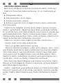
Dear User,
Our objective is to make this product provide you with the best output
which is manufactured in our modern facilities in a careful working
environment, in compliance with total quality concept.
Therefore, we suggest you to read the user manual carefully before
using the product and, keep it permanently at your disposal.
Note: This user manual is prepared for more than one model. Some
of the features specied in the Manual may not be available in your
appliance.
All our appliances are only for domestic use, not for commercial use.
‘‘THIS APPLIANCE SHALL BE INSTALLED IN ACCORDANCE WITH THE
REGULATIONS FORCE AND ONLY USED IN A WELL VENTILATED SPACE.
READ THE INSTRUCTIONS BEFORE INSTALLING OR USING THIS APPLIANCE’’
“Conforms with the WEEE Regulations.”
GB

3
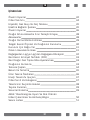
CONTENTS
Important Warnings
4
Introduction Of The Appliance
6
Injector, Gas Flow And Power Table
7
Electrical Connection Scheme
7
Important Warnings
8
If Built-In Oven Is Placed Under Cooktop
10
Accesories
10
Installation Of Cooktop
11
Counter Cutting Sizes And
Installation Of Your Cooktop
12
Correct Place For Installation
13
Ventilation Of Room
13
Transformation From Natural Gas To Lpg And
From Lpg To Natural Gas
14
Gas Breaking Safety Appliance (FFD)
15
Setting Gas Cooktop As Per Gas Type
15
Usage Of Your Cooktop
15
Pot Diameter
16
Maintenance And Cleaning
17
Product Information 18
Energy Saving Hints 19
Appliance Class And Category 19
Customers’ Right Of Choice 20
Handling Rules
21
Trouble Shooting
21
Environmentally-Friendly Disposal And
Package Information
22
Service List
23
GB

4
IMPORTANT WARNINGS
1. WARNING: Before touching the connection terminals,
all supply circuit should be disconnected.
2. WARNING: Any inadvertent cooking made with fats
and oils can be dangerous and cause re.
3. WARNING: Risk of re; do not store the food
materials on the cooking surface.
4. WARNING: During usage the reachable sections can
be hot. Keep the small children away.
5. WARNING: The appliance and its reachable sections
become hot during usage.
6. The setting conditions of this appliance is
indicated on the label. (Or data tag)
7. This appliance is not connected to a combustion prod-
uct discharge system.This appliance shall be connected
and installed as per the applicable installation legislation.
Consider the requirements related with ventilation.
8. Using a gas hob will release humidity and combus-
tion products in the room where it resides. Especially
during when the appliance in use, ensure that the kitch-
en is well ventilated and retain the natural ventilation
holes or install a mechanical ventilation system. (Hood
on top of the oven) Sustained usage of the appliance
may require additional ventilation. For example opening
a window or if available, increasing the ventilation level
of a mechanical ventilation system.
9. WARNING: The appliance is intended for cooking only.
It must not be used for other purposes like room heating.
GB

5
10. This appliance should be installed as per regula-
tions and in well-ventilated location only. Read the in-
structions before installing or operating the appliance.”
11. Before placing the appliance check the local
conditions (gas type and gas pressure) and ensure
that the settings of the appliance is appropriate.
12. These instructions are applicable for countries of
which symbols are indicated on the appliance. If the
country symbol is not available on the appliance, in
order to adapt the appliance to the conditions of such
country, the technical instructions should be read.”
13. Do not operate the system for more that 15
seconds. If the burner does not ignite at the end of
15 seconds stop the operation of the system and open
the section door and/or wait for at least 1 minute
before igniting the burner.
14. Do not use steam cleaners to clean the appliance.
15. NEVER try to extinguish a re with water, rst
disconnect the mains supply and then using, for
example a lid or blanket, cover the re.
16. Unless continuous supervision is provided, the
children of age 8 or below should be kept away.
17. Pay attention for not to touch the heating elements.
18. This appliance can be used by children aged
from 8 years and above and persons with reduced
physical, sensory or mental capabilities or lack of
experience and knowledge if they have been given su-
pervision or instruction concerning use of the appliance
in a safe way and understand the hazards involved.
GB

6
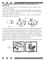
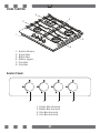
INTRODUCTION OF THE APPLIANCE
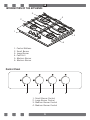
Control Panel
1. Control Buttons
2. Small Burner
3. Large Burner
4. Cast Grill
5. Medium Burner
6. Medium Burner
1. Small Burner Control
2. Large Burner Control
3. Medium Burner Control
4. Medium Burner Control
1
2
3
4
5
6
1 2 3 4
GB

7
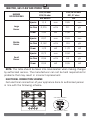
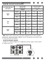
INJECTOR, GAS FLOW AND POWER TABLE
BURNER
SPECIFICATIONS
G20,20 mbar
G25,25 mbar
G30,28-30 mbar
G31,37 mbar
Gas Natural LPG
Large
Burner
Injector 1,15 mm 0,85 mm
Gas Flow 0,276 m³/h 211 g/h
Power 2,90 kW 2,90 kW
Middle
Burner
Injector 0,97 mm 0,65 mm
Gas Flow 0,162 m³/h 124 g/h
Power 1,70 kW 1,70 kW
Small
Burner
Injector 0,72 mm 0,50 mm
Gas Flow 0,96 m³/h 69 g/h
Power 0,95 kW 0,95 kW
NOTE: This table should be taken into consideration when making changes
by authorized service. The manufacturer can not be held responsible for
problems that may result in incorrect replacement.
ELECTRICAL CONNECTION SCHEME
Get electrical connection of your appliance done to authorized person
in line with the following scheme.
L1
220-240V~50/60Hz
H05 VV-F 3G 1.5mm²
Earth
Neutral
GB

8
IMPORTANT WARNINGS
Electrical Connection and Safety
1.Setting conditions of this appliance is indicated in tag or data plate.
2.This appliance is not connected to any discharging apparatus of
burning products. It should be connected and installed according to
applicable assembly regulation.
3.Great attention should be paid on ventilation related conditions.
4.Your appliance should be connected to an appropriate fuse according
to electric power. If necessary, it is recommended that connection is
made by authorized service.
5.Your appliance is congured in accordance with electrical supply of
220-240V, 50/60Hz.
6.If main electrical network is different from these values, contact with
your authorized service.
7.Electrical connections of your appliance should only be made to the
fuses having suitably wired grounding (grounded) system. If no conven-
ient fuse is available in the place where your appliance is to be installed,
contact with authorized service immediately. Manufacturing rm is not
responsible denitely for the damages that fuses whose grounding is not
made and connected to the appliance can cause.
8.Plug of the appliance should be close to be accessed easily to the
fuse whose grounding is made without use of extension cord.
9.Do not allow contacting the power cable of your appliance with hot
regions. Similarly, keep away it from sharp edges and corners.
10.If feeder cord is damaged, this cord should be replaced either by
manufacturer or its service agency or same degree qualied personnel in
order to hinder a dangerous situation.
11.Wrong electrical connection may give damage to the appliance. In
this case, your appliance will remain out of guarantee scope. Electrical
connection of your appliance should be done by authorized service.
12.During operation of cooktop, some parts may be hot. When you also
bring switches closed position, it may remain hot for a while. Children
should be kept away every time and not be left without observation.
GB

9
Gas Connection and Safety
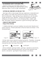
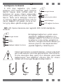
1. For LPG (cylinder) connection, afx
metal clamp on the hose coming from LPG
cylinder. Afx an edge of the hose on hose
inlet connector behind the appliance by
pushing to end through heating the hose
in boiled water. Afterward, bring the clamp
towards end section of the hose and tighten
it with screwdriver. The gasket and hose
inlet connector required for connection is
as the picture shown below.
NOTE: The regulator to be afxed on LPG cylinder should have 300
mmSS feature.
2. Natural gas connection should be
done by authorized service. For natural
gas connection, place gasket in the nut
at the edge of natural gas connection
hose. To install the hose on main gas
pipe, turn the nut. Complete the con-
nection by making gas leakage control.
Gas hose and electric connection of the appliance should
not pass next to hot areas such as back of the appliance.
Gas hose should be connected by making wide angle turns
against breaking possibility. Movement of appliance whose
gas connection is made may cause gas leakage.
Main Gas Pipe
Gasket
Hose Inlet Connector
Metal Clamp
Lpg Connection Hose
Main Gas Pipe
Gasket
Nut
Natural Gas Connection Hose
True
False
True
True
GB

10
3. Connect your appliance to gas cock from the shortest way and in
a manner to prevent any leakage. For safety, the hose used should be
maximum 125 cm and minimum 40 cm.
4. While making gas leakage control; never use lighter, match, glowing
cigarette or similar inammable matter.
5. Apply soap bubble on connection point. If any leak/leakage exists,
foaming will occur on soaped region.
6. If the cooktop is to be mounted on a cabinet or openable drawer,
a heat protection panel having 15 mm minimum opening should be
mounted under the cooktop.
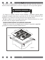
IF BUILT-IN OVEN IS PLACED UNDER COOKTOP;
Gas pipe should be afxed
in a way not to touch the
oven below, sharp edges and
corners, not to be pulled in
a manner to be twisted and
strained. Make gas connection
from right part of the cooktop,
fasten the hose by use of
clamp.
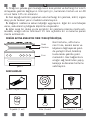
ACCESORIES
Cooktop
Hose
Oven
Figure 1
Support piece (4 pcs.)
Roving (1 pcs.) Hose inlet connector (1 pcs.)
Injector (1 set) Screw (4 pcs.) Coffee adaptor (1 pcs.)
GB

11
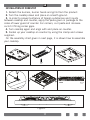
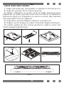
INSTALLATION OF COOKSTOP
1. Detach the burners, burner hoods and grills from the product.
2. Turn the cooktop down and place on smooth ground.
3. In order to prevent entrance of foreign substances and liquids
between cooktop and counter, apply the paste given in package to the
sides of lower guard of counter. For corners, curl paste and increase
curls till lling corner gaps.
4. Turn cooktop again and align with and place on counter.
5. Fasten up your cooktop on counter by using the clamp and screws
supplied.
On the assembly chart given in next page, it is shown how to assemble
your cooktop.
Roving
Figure 2
GB

12
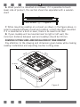
6. When product is mounted on a drawer, if it is possible to touch
lower side of product, this section should be separated with a wooden
shelf.
7. While mounting cooktop on a closet, as shown in the gure above, in
order to separate between closet and cooktop, a shelf should be mounted.
If it is mounted on a built-in oven, there is no need to do that.
8. If your cooktop will be mounted next to right or left wall, the
minimum distance between wall and cooktop should be 50 mm.
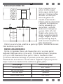
COUNTER CUTTING SIZES AND INSTALLATION OF YOUR COOKTOP
Pay attention to the drawing and dimension given below while making
cooktop installation and adjusting counter cutting sizes.
min. 30 mm
Figure 3
520 mm
490 mm
590 mm
560 mm
min. 60 mm
min. 60 mm
min. 60 mm
Figure 4
GB

13
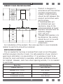
CORRECT PLACE FOR INSTALLATION
Product is designed in
accordance with the kitchen
counters supplied from
market. A safe distance
should be left between the
product and kitchen walls
and furniture.
If hood/aspirator will
be installed over your
appliance, obey to the
recommendation of hood/
aspirator manufacturer for
assembly height.
(min. 65 cm)
The gap that cooktop is to
be placed on the counter
should be cut in line with
cooktop installation
dimensions.
For installation of the product, the rules specied in local standards
related to electricity should be complied.
VENTILATION OF ROOM
The air needed for burning is received from room air and the gases
emitted are given directly in room. For safe operation of your product,
good room ventilation is a precondition. If no window or room to be
utilized for room ventilation is available, additional ventilation should
be installed. However, room has a door opening outside, it is no needed
to vent holes.
Room Size Ventilating Opening
Smaller than 5 m³ min. 100 cm²
Between 5 m³ - 10 m³ min. 50 cm²
Bigger than 10 m³ no need
In basement or cellar min. 65 cm²
650 mm min.
GB

14
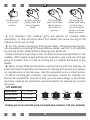
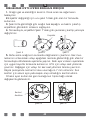
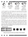
TRANSFORMATION FROM NATURAL GAS TO LPG AND FROM LPG TO
NATURAL GAS
1. Turn off gas and electricity of the cooktop. If your cooktop is hot,
wait for cooling down.
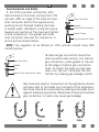
2.For injector change, use a screwdriver whose edge is as the Figure 5.
3. As seen in Figure 6, demount burner lid and burner of the cooktop
and ensure visibility of injector.
4. Remove injector by turning as shown in Figure 7 with screwdriver
and replace it with a new one.
5. After that, detach control switches of the cooktop. Make setting by
turning the screw in the middle of gas cocks with a small screwdriver
in the manner shown in the following picture. To adjust ow rate screw,
use a screwdriver having suitable dimension. For LPG, turn the screw
clockwise. For natural gas, turn the screw one time counter clockwise.
At low position, length of normal ame should be 6-7 mm. For the last
control, check out whether ame is open or closed.
Setting of your appliance may differ according to the type of gas cock
used.
Figure 5
Figure 6
Figure 7
Injector
Control
Switch
Figure 8 Figure 9
GB

15
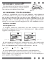
GAS BREAKING SAFETY APPLİANCE (FFD)
Against putting out to be taken place as a
result of liquid overow at upper burners, safety
appliance steps in and cut gas immediately.
SETTING GAS COOKTOPS AS PER GAS TYPE
Gas type (LPG or natural gas) that your appliance is manufactured
foris stated in the label found behind the product and that show
technical features. If gas setting of your appliance is not the same
as gas setting of your network, it should be adjusted by making
change by an expert person. In the following table, injector, gas
ow and power values of appliance is given according to gas type.
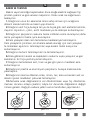
USAGE OF YOUR COOKTOP
Usage of Gas Cooktop
1. Before starting to use your cooktop, be sure burner hoods are at
correct position. Correct placement of burner hoods are shown in the
following gure.
2. Gas cocks have a special locking mechanism. Therefore, to operate
cooktop zone, press button by pushing ahead and while opening or
closing the cock, hold down the button.
Closed Fully open Half open
3. For automatic igniting models, igniting is realized via electricity.
Therefore, before operating appliance, be sure that appliance has
electric connection. Igniting for these models is as follows.
Figure 10
FFD
Figure 11 Figure 12
GB

16
4. Pay attention that cooktop grills are placed on cooktop table
completely. In case of failure about this matter can cause pouring of the
materials to be put on that.
5. For the models having gas putting out safety, following realizing igni-
tion procedure according to the guidelines above, wait for 5-10 seconds
by pushing button ahead without keeping your hands off.
Safety mechanism will step in this duration and ensures operation of the
cooktop. With regard to gas putting out appliance, gas cock cuts the gas
going to cooktop zone in case of putting out of cooktop ame due to any
reason.
6. While using coffee pot apparatus supplied along with the cooktop, be
sure that foots of apparatus are placed on cooktop grill exactly and remain
on cooktop zone in centred way. Use the apparatus only on small burner.
7. While utilizing gas cooktops, use saucepan, placed on cooktop sur-
face as far as possible. Thanks to that, you can save energy. In the follow-
ing table, cooking pot diameters recommended to be used as per burners
are given.
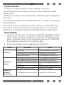
POT DIAMETER
Small Burner 12-18 cm
Middle Burner 18-20 cm
Large Burner 22-24 cm
Cooking pot to be used with products should have minimum 120 mm. diameter.
Cooktop cock
is at closed
position.
To ignite cooktop,
rstly press the
button towards
ahead.
While holding
down the button,
lighter steps in
and starts to
ignition.
By turning the
button right while
holding down,
you can provide
ignition at ame
length you want.
False False False True
GB

17
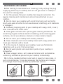
MAINTENANCE AND CLEANING
Before starting to maintenance or cleaning, rstly unplug the plug
supplying electricity to cooktop and turn off gas valve. If cooktop is
hot, wait for cooling down.
1. For the purpose that your cooktop has long and economic life,
regular cleaning and maintenance should be performed on your
cooktop.
2. Do not clean your cooktop with scratching tools such as bristle
brush, wire wool or knife. Do not use abrasive, scratching, acid materials
or detergent.
3. Following mopping parts of your cooktop with soapy cloth, rinse it,
later rinse well with a soft cloth.
4. Clean glass surfaces with special glass cleaning substances. As
scratching of glass surfaces leads to breaking, while cleaning glass
surfaces, do not use abrasive cleaners or sharp metal scrapers.
5. Do not clean your cooktop with steamy cleaners.
6. Clean channels and lids of cooktop zones with soapy water and
clean gas channels with a brush.
7. In the course of cleaning your cooktop, never use ammable
materials such as acid, thinner and gas.
8. Do not wash plastic and aluminium parts of your cooktop in
dishwasher.
9. Clean vinegar, lemon, salt, coke and similar acid and alkaline
containing substances poured on your cooktop immediately.
10. In time, cooktop buttons turns hard or never turn any more, in
such circumstances, it may be necessary that buttons are changed.
The change should only be done by authorized service.
Figure 13 Figure 14
Figure 15
GB

18
GB
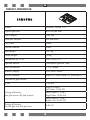
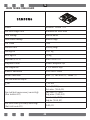
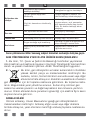
PRODUCT INFORMATION
Model NA64M7100AW / TR
Type of gas hob Built-in Gas Hob
Pan Support Cast Iron
Wok pan Support Not Available
Top Plate Glass
Control Handle Silver
Net Weight 14,7 kg
Gross Weight 16 kg
Dimension (W*D*H) 590 x 520 x 57
Ignition device Continuous Ignition Type
Gas Connection G 1/2 Thread
Electric supply 220-240V~50Hz
Burner Feature Rapid (1), Semi rapid (2), Auxiliary (1)
Number of gas burners 4
∑Qn
7,25 kW
Energy efciency
per gas burner (EE gas burner)
Rapid (2,9kW),
Left Rear: (%54,45)
Semi Rapid (1,7kW),
Right Rear: (%55,34)
Semi Rapid (1,7kW),
Right Front (%55,52)
Energy efciency
for the gas hob (EE gas hob)
%55,10

19
GB
ENERGY SAVING HINTS
• Ensure the lid ts properly in order to save energy. Furthermore, if
you use a glass lid you can effectively monitor the cooking process.
• Use as little water as possible when cooking.
• Use adequately sized pots and pans for the amount of food. For
small quantities use pots and pans that are adapted to the amount
of food. For example if you are preparing only 350 g of broccoli, use
small cookware (diameter of bottom approx. 15 cm).
• Use pots and pans made of heat conducting materials; steel or
enamelled cast-iron pans and pots will heat up more quickly and
consume less energy than glass or ceramic cookware, for example.
• Use the lowest power setting that allows water to boil. Reduce the
ongoing power setting as much as possible to keep the required
temperature.
• Make sure the cookware is centred on the heating element
APPLIANCE CLASS AND CATEGORY
TURKEY (TR)
Category II 2H3B/P
P (mbar) G20-20mbar, G30-30mbar

20
GB
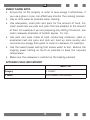
CUSTOMERS’ RIGHT OF CHOICE
In case of realising that the product is defective, the consumers can
use their right stated in the Article 11 of the Law on Protection of the
Consumer No 6502 as below;
a- Withdrawal of contract,
b- Claiming discount over sale price,
c- Claiming repair free of charge,
d- Claiming another non-defective copy of the same product.
If the consumer prefers the free repair amongst these rights, then the
seller is liable to overhaul the product without asking any other price
under the name of anything such as labour, price for the replaced part
or anything else. The consumer can use the right of free repair against
the manufacturer or importer. Reseller, manufacturer and importer are
severally responsible for the customer to use the before-mentioned right.
If the consumer uses the right of free repair;
- In case the product is malfunctioned again within the warranty period,
- In case the maximum duration required for repairing is exceeded,
- In case the product is reported as irreparable by the authorised
service station, seller, manufacturer or the importer, the consumer can
claim for refund, discount on the product in proportion to defectiveness
or if possible, for replacement of the product with a non-defective copy
from the reseller. The seller cannot decline this demand posed by the
consumer. If this demand is not fullled, then the seller, the manufacturer
and the importer shall severally be held responsible.
If the Certicate of Warranty is not given by the seller, the consumer
can apply to the General Directorate of Ministry of Customs and Trade,
Protection of the Consumer and Market Surveillance.
The consumer may also le an application -for any complaints and
objections that may arise over conict- to the Arbitration Committee for
Consumer Problems or Consumer Court which is located at the area he /
she resides.
Sayfa yükleniyor...
Sayfa yükleniyor...
Sayfa yükleniyor...
Sayfa yükleniyor...
Sayfa yükleniyor...
Sayfa yükleniyor...
Sayfa yükleniyor...
Sayfa yükleniyor...
Sayfa yükleniyor...
Sayfa yükleniyor...
Sayfa yükleniyor...
Sayfa yükleniyor...
Sayfa yükleniyor...
Sayfa yükleniyor...
Sayfa yükleniyor...
Sayfa yükleniyor...
Sayfa yükleniyor...
Sayfa yükleniyor...
Sayfa yükleniyor...
Sayfa yükleniyor...
Sayfa yükleniyor...
Sayfa yükleniyor...
Sayfa yükleniyor...
Sayfa yükleniyor...
Sayfa yükleniyor...
Sayfa yükleniyor...
Sayfa yükleniyor...
Sayfa yükleniyor...
Sayfa yükleniyor...
Sayfa yükleniyor...
Sayfa yükleniyor...
Sayfa yükleniyor...
Sayfa yükleniyor...
Sayfa yükleniyor...
Sayfa yükleniyor...
Sayfa yükleniyor...
Sayfa yükleniyor...
Sayfa yükleniyor...
Sayfa yükleniyor...
Sayfa yükleniyor...
-
 1
1
-
 2
2
-
 3
3
-
 4
4
-
 5
5
-
 6
6
-
 7
7
-
 8
8
-
 9
9
-
 10
10
-
 11
11
-
 12
12
-
 13
13
-
 14
14
-
 15
15
-
 16
16
-
 17
17
-
 18
18
-
 19
19
-
 20
20
-
 21
21
-
 22
22
-
 23
23
-
 24
24
-
 25
25
-
 26
26
-
 27
27
-
 28
28
-
 29
29
-
 30
30
-
 31
31
-
 32
32
-
 33
33
-
 34
34
-
 35
35
-
 36
36
-
 37
37
-
 38
38
-
 39
39
-
 40
40
-
 41
41
-
 42
42
-
 43
43
-
 44
44
-
 45
45
-
 46
46
-
 47
47
-
 48
48
-
 49
49
-
 50
50
-
 51
51
-
 52
52
-
 53
53
-
 54
54
-
 55
55
-
 56
56
-
 57
57
-
 58
58
-
 59
59
-
 60
60


diğer dillerde
- English: Samsung NA64M7100AW User manual
İlgili makaleler
Diğer belgeler
-
Hoover HMM6724SHX Kullanım kılavuzu
-
Arnica Tostit Izgaralı Tost Makinesi Kullanım kılavuzu
-
-
-
Whirlpool HBG L20 B El kitabı
-
-
Ariston PF 640 ES (WH) Kullanici rehberi
-
Electrolux EHM6335X Kullanım kılavuzu
-
Siemens HR745533T Kullanım kılavuzu
-