
Scrubber User Manual
AS430B & AS510B

T
ABLE OF CONTENTS
EN
GLISH USER MANUAL…………………….…... …………………….. 1-18
DEUTSCH BETRIEBSANLEITUNG………………………………………. 19-37
FRANÇAİS MANUEL UTILISATEUR………………………………………. 38-55
NEDERLANDS GEBRUIKERS HANDLEIDING …………………………….. 56-73
ITALIANO MANUALE D’USO……………………………………………... 74-91
ESPAÑOL ISTRUZIONI PER L’USO……………………………………… 92-110
PORTUGUÊS MANUAL DO UTILIZADOR…………………………………... 111-128
ΕΛΛΗΝΙΚΆ ΕΓΧΕΙΡΙΔΙΟ ΧΡΗΣΤΗ …………………………………….…. 129-147
TÜRKÇE KULLANIM KILAVUZU…………………………………….….. 148-165
ČESKÝ UŽIVATELSKÝ MANUÁL……………………………………... 166-183
POLSKI INSTRUKCJA OBSŁUGI……………………………………… 184-201
MAGYAR FELHASZNÁLÓI KÉZIKÖNYV………………………………..
202-219
ROMÂNĂ MANUALUL UTILIZATORULUI…………………………….... 220-237
РУССКИЙ НСТРУКЦИЯ ПО ПРИМЕНЕНИЮ……………………..…… 238-256
БЪЛГАРСКИ РЪКОВОДСТВО НА ПОТРЕБИТЕЛЯ……………………... 257-274
SLOVENŠČINA NAVODILA ZA UPORABO ………………………………….. 275-292
DANSK BRUGERMANUAL…………………………..……….……….. 293-310
SVENSKA BRUKSANVISNING…………………………………………….
31
1-328
NORSK BRUKERHÅNDBOK……………………………………………
329-346
SUOMI KÄYTTÄJÄN OPAS...............………..………………………. 347-364

USER MANUAL
1
EN
GLISH
T
ABLE OF CONTENTS
INT
RODUCTION .................................................................................................................................... 2
MANUAL CONTENTS .................................................................................................................... 2
PURPOSE ....................................................................................................................................... 2
SPARE PARTS AND MAINTENANCE ............................................................................................ 2
CHANGES AND IMPROVEMENTS ............................................................................................... 2
SCOPE OF APPLICATION ............................................................................................................. 2
IDENTIFICATION DATA .................................................................................................................. 2
UNPACKING/TRANSPORT ............................................................................................................ 2
GENERAL SAFETY GUIDES ......................................................................................................... 3
TECHNICAL DATA .......................................................................................................................... 4
MACHINE DESCRIPTION ..................................................................................................................... 4
MACHINE STRUCTURE ................................................................................................................ 4
CONTROL PANEL .......................................................................................................................... 5
DISPLAY WINDOW OF CHARGER INDICATION LIGHT .............................................................. 6
GUIDE FOR USE ................................................................................................................................... 6
INSTALLING AND SETTING THE BATTERY OF THE NEW MACHINE ....................................... 6
INSTALLING BATTERY AND SETTING BATTERY TYPE(WET OR GEL/AGM)...................... 7
BEFORE MACHINE START-UP ..................................................................................................... 8
INSTALLING AND UNLOADING THE BRUSH / PAD-HOLDER .................................................... 8
ADJUSTING THE BALANCE OF THE SQUEEGEE ...................................................................... 9
REGULATING THE VOLUME OF WATER FLOW ......................................................................... 9
MACHINE START AND STOP ...................................................................................................... 10
MACHINE OPERATION (SCRUBBING AND DRYING) ............................................................... 10
TANK EMPTYING ......................................................................................................................... 11
AFTER USING THE MACHINE .................................................................................................... 12
PERIODS OF INACTIVITY ........................................................................................................... 12
USING FOR THE FIRST TIME ..................................................................................................... 12
MAINTENANCE AND CARE ............................................................................................................... 12
SCHEDULED MAINTENANCE TABLE ........................................................................................ 13
BATTERY CHARGING.................................................................................................................. 13
SQUEEGEE CLEANING .............................................................................................................. 14
SQUEEGEE BLADE CHECK AND REPLACEMENT................................................................... 14
BRUSH/POLISHING PAD CLEANING ......................................................................................... 15
WATER TANK AND FLOAT FILTER MESH CLEANING ............................................................ 15
SOLUTION FILTER CLEANING ................................................................................................... 16
CIRCUIT FIGURE OF AS430B AND AS510B .............................................................................. 17
TROUBLESHOOTING ......................................................................................................................... 18
MACHINE DISPOSAL ......................................................................................................................... 18

USER MANUAL
2
EN
GLISH
INTR
ODUCTION
NOT
E
The numbers in brackets refer to the related components shown in Machine
Description section.
MANUAL CONTENTS
This
manual is to provide the operator with the necessary information to use this machine properly
and safely. The information includes the technical data, safety, operation, storage, maintenance
and disposal of the machine. The operator and technicians with related qualifications must study
this manual carefully before commencing the operation and maintenance of this machine. Please
contact VIPER for any queries on the explanation of this manual or when further related
information is needed.
PURPOSE
The
intention of this manual is to enable the operator and qualified technicians to accomplish the
maintenance of this machine.
The operator must not perform those operations that should only be performed by technicians.
VIPER will not be responsible for any damages caused by the violation of this rule.
SPARE PARTS AND MAINTENANCE
All
necessary operation, maintenance, and repair procedures must be performed by qualified
personnel or by the service centers of VIPER
Only Authorised spare parts and accessories should be used.
If service and ordering of spare parts or accessories are needed, please contact VIPER with the
model number of the machine and serial numbers.
CHANGES AND IMPROVEMENTS
VIP
ER makes continuous improvements on its products. VIPER reserves the right of changing
and improving the machines, and also the right of deciding by itself whether the benefits brought
about by the changes are applicable to the products already sold. All changes or extra
accessories must be agreed by VIPER and must be performed by the company.
SCOPE OF APPLICATION
This
scrubber is used in a domestic and industrial environment, and is suitable for the cleaning of
smooth and hard floors (scrubbing and waste water collection). It must be used by qualified
operators and in a safe environment. This scrubber can not be used for cleaning outdoors, on
carpets, and on relatively coarse floors.
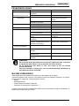
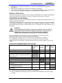
IDENTIFICATION DATA
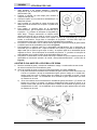
The m
achine model and serial number are marked on the plate (4).
This information is useful when requiring machine spare parts, Use the following table to write
down the machine identification data.
MACHINE mode
..................................................................
MACHINE serial number
.......................................................
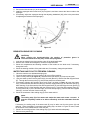
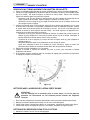
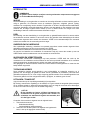
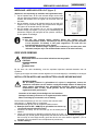
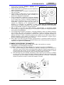
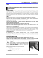
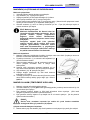
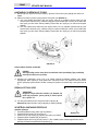
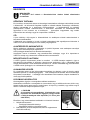
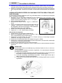
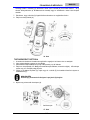
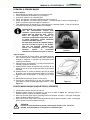
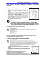
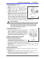
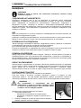
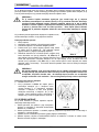
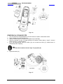
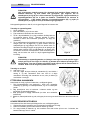
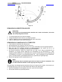
UNPACKING/TRANSPORT
Please
follow carefully the instructions on the package when unpacking.
On delivery, please inspect the packing and the machine to ensure no
damage has been done during transport. If there is any visible damage,
please keep the original form, and ask the carrier to confirm and fill out a
list of damages for compensation.
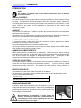
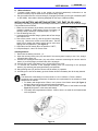
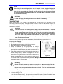
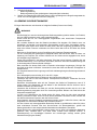
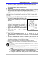
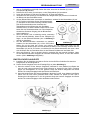
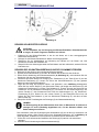
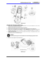
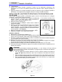
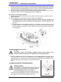
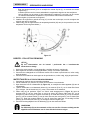
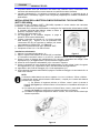
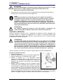
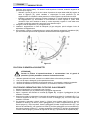
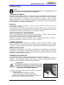
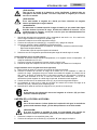
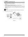
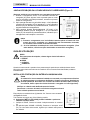
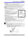
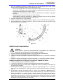
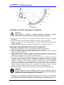
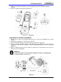
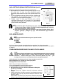
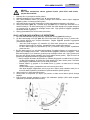
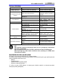
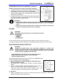
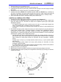
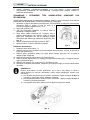
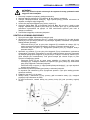
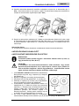
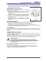
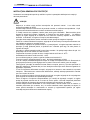
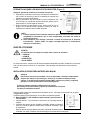
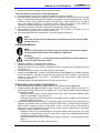
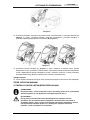
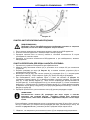
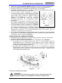
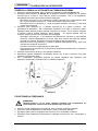
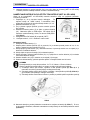
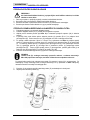
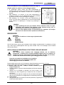
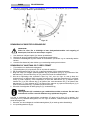
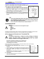
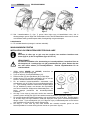
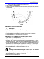
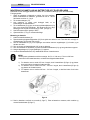
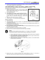
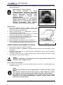
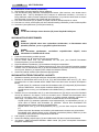
- CAUTION
When unpacking and unloading, or during moving the
machine across ground with steps, please take care to
avoid hitting the on/off switch regulating the water flow,
Part A in the figure on the right.

USER MANUAL
3
EN
GLISH
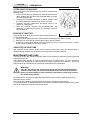
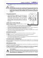
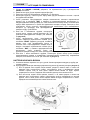
Ch
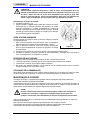
eck if the machine is equipped with the following items:
1. Technical documents
- Scrubber User Manual
- On-board Charger Manual (if equipped)
2. connector for Charger (if not equipped with on-board charger, it is on the specified external
charger)
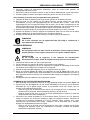
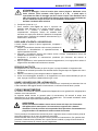
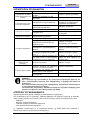
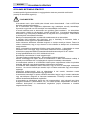
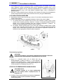
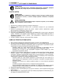
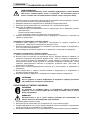
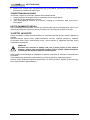
GENERAL SAFETY GUIDES
The
following are special warnings and notices on potential damages (personnel and machine):
WARNING!
- Machine may only be operated under the guidance of this manual. Only accessories
approved by VIPER should be used.
- This machine must be only used by duly trained or authorised personnel. Children or
inappropriate persons must not use this machine.
- Under normal use, the battery may emit inflammable gas. The battery must be kept away
from radiating, illuminating, and burning items as well as sparks. When the machine is being
used, please ensure that the environment is well ventilated and is away from naked flames.
When charging, please do not smoke in the vicinity of the machine.
- Please disconnect the battery prior to the performance of any maintenance/repair operations.
- Before using the on-board charger, please ensure that the values of voltage and frequency as
indicated on the serial number sticker match those of the mains.
- When working near electrical parts, please do not wear any jewelry. Please take all
precautionary measures to avoid the hair, jewelry, and loose fitting clothes from being caught
by any moving parts of the machine.
- Please do not use this machine in particularly dirty areas. Do not wash the machine directly
with water. Do not let the machine come in touch with corrosive liquids.
- The temperature for storage and for working environment of the machine must be between 0 -
40
0
C.
- The h
umidity of air must be between 30% - 105%.
- Please do not use the machine on a slope with a gradient of more than 2%.
- In case of fire, please use dry powder fire extinguishers. Do not use liquid fire extinguishers.
- Particular attention should be paid when the machine is transported below 0
0
C. The water
tank and the water in the hoses may freeze and cause serious damages to the machine.
- Use brushes and pads supplied with the machine and those specified in the User Manual.
Using other brushes or pads could reduce safety.
- In case of machine malfunction, please make sure that it is not caused by lack of maintenance.
If it is caused by other conditions, please seek the assistance of authorised personnel or the
service center.
- If it is confirmed that the spare parts must be replaced, please secure the genuine parts from
authorised dealers or agents.
- In order to ensure the safe and proper operation of the machine, please let authorised
personnel or the service center perform the scheduled maintenance according to the
maintenance schedules in the related sections of the manual.
- This machine must be properly disposed of because there may exist poisonous and
hazardous matters (batteries, etc.), and these matters must be disposed of by special centers
in accordance with related laws and regulations (please refer to machine disposal section).

USER MANUAL
4
EN
GLISH
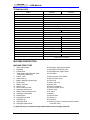
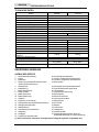
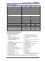
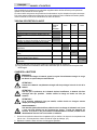
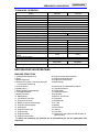
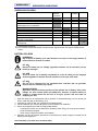
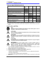
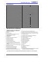
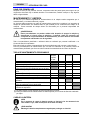
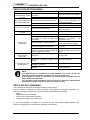
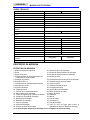
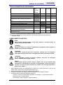
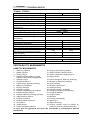
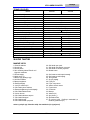
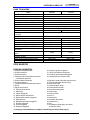
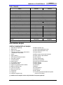
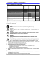
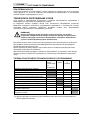
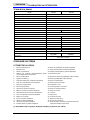
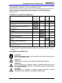
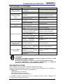
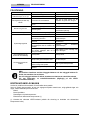
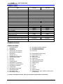
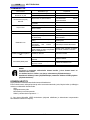
TECHNICAL DATA
Mode
l AS430B AS510B
Mach
ine Height 980mm
So
lution tank capacity 40 litre
Re
covery tank capacity 40 litre
Dia
meter of transport wheel 200mm
Dia
meter of guide wheel 76mm
Power
of vacuum system motor 350w
Maxi
mum gradient when working
2%(Max)
Sou
nd pressure level at workstation
70dB(A)±3dB(A)
S
tandard batteries (2×12V) 24V 85Ah AGM
(2×12V) 2
4V 105Ah AGM
Battery compartment size (W x L x H) 340 x 330 x 260mm(Max)
Vacuum system circuit capacity
1200 mm H
2
O
Clean
ing width
430mm 510mm
Squeegee width
730mm 790mm
machine maximum length
1060mm 1100mm
Mach
ine width without squeegee
480mm 540mm
Brush
diameter
430mm 510mm
We
ight with batteries and with empty tanks
112kg 128kg
Gr
oss weight of the machine ready for use 152kg 168kg
Brush
motor power
550W 560W
Brush s
peed
150rpm
Brush /pad-holder Maximum pressure
30kg (Max) 35kg(Max)
Packing size (Lx W x H)
1200 x 610 x 1170mm
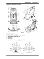
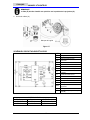
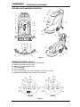
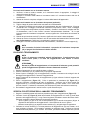
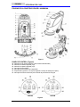
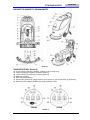
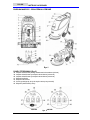
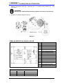
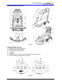
M
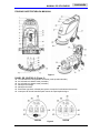
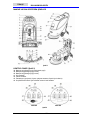
ACHINE DESCRIPTION
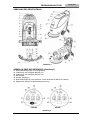
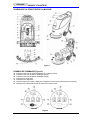
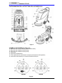
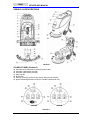
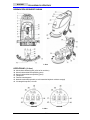
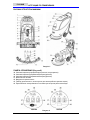
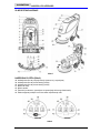
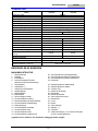
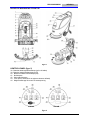
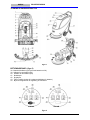
MACHINE STRUCTURE
1. Sa
fety switch button 20. Squeegee adjusting handwheel
2. Handlebar 21. Squeegee rear support frame
3. Control panel 22. Squeegee front support frame
4. Serial number plate/Technical data
/ Conformity certification
23. Cup holder
5. Control cover 24. Recovery tank cover handle
6. Cable holder (*) 25. Recovery tank cover
7. Battery charging indication light 26. Tank body
8. Reset switch 27. Water inlet cover
9. Battery connector 28. Brush deck
10. Battery cover 29. Brush / pad-holder
11. Vacuum tube for waste 30. Vacuum system motor
12. Squeegee drawing cord 31. Brush motor
13. Battery connector safety cover 32. 8” wheel
14. Squeegee lifting handle 33. Battery
15. Draining hose 34. Vacuum tube
16. Squeegee fixed knob 35. Charger (*)
17. Squeegee clip 36. Float filter
18. Squeegee blade 37. Water level tube ( to indicate amount of water
in
Solution tank)
19. Squeegee support frame
(*) applicable only to machines already installed with on-board charger (optional)

USER MANUAL
5
EN
GLISH
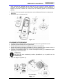
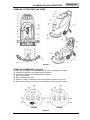
FIGURES OF MACHINE STRUCTURE
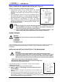
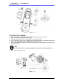
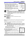
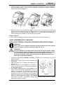
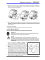
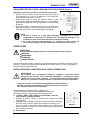
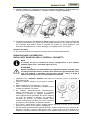
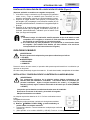
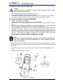
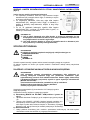
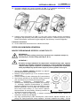
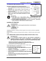
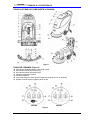
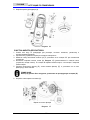
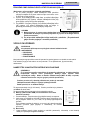
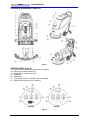
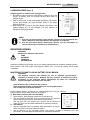
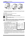
CONTROL PANEL (Figure2)
38. Batt
ery charge indication light (green when saturated)
39. Battery exhausted indication light (red)
40. Battery exhausted indication light (red)
41. Power switch
42. Vacuum switch
43. Timer (optional, used to record working time of brush)
44. Solenoid valve switch for water spraying control
A
S430B AS510B
Figure 2
Figure 1

USER MANUAL
6
EN
GLISH
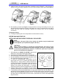
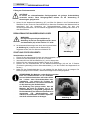
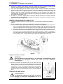
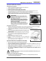
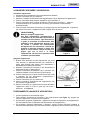
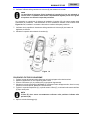
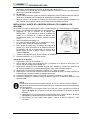
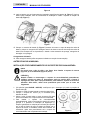
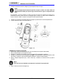
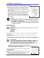
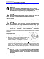
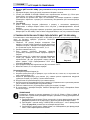
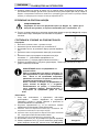
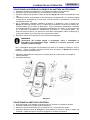
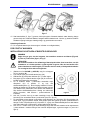
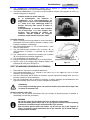
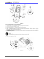
DISPLAY WINDOW OF CHARGER INDICATION LIGHT (Figure 3)
(O
ptional, applicable to models with built-in charger)
1. When charging starts, the red indication light of the charger
(45)flashes a few times and then steadies to become a
permanent red indication light, entering into the first stage of
charging;
2. After charging for a period of time, the red indication light of
the charger (45) will go out, A yellow indication light (46) will
light up permanently: entering the second stage of charging;
3. After charging for approximately 10 hours, the amber
indication light (46) will turn off, (47) The green indication light
will become permanently lit, indicating that the charge is full,
and charging has ended.
NOT
E
1) Du
ring charging, If the yellow indication light flashes: the battery is not of the
type compatible to the charger, or the battery is not properly connected, or a
short circuit has taken place at the output terminal.
2) If the red indication light is flashing: a short circuit inside the charger. (For
details, please refer to the related sections in the charger instruction.)
GUIDE
FOR USE
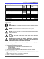
WARNING
On certain parts of the machine are pasted some indicative signs:
- DANGER
- WARNING
- CAUTION
- CONSULTATION
When reading this manual, the operator must pay particular attentions to the symbols on these signs.
Under no circumstances shall these signs be covered. If they are damaged, please replace
immediately.
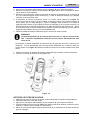
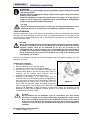
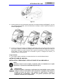
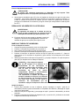
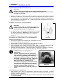
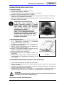
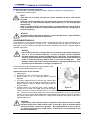
INSTALLING AND SETTING THE BATTERY OF THE NEW MACHINE
W
ARNING
If
the battery is incorrectly installed or inaccurately connected, the electric
com
ponents of the machine may be seriously damaged. The battery may only be
installed by qualified personnel. According to the battery model number (WET or
GEL) being used, set the functional circuit board and on-board charger (optional).
Please check if the battery is damaged before installing.
Disconnect the battery connector and the on-board charger plug.
Be careful when touching the battery.
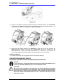
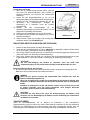
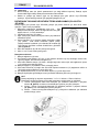
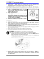
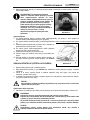
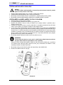
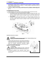
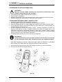
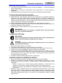
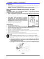
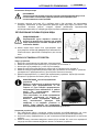
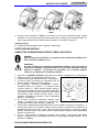
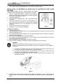
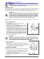
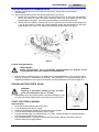
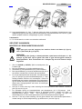
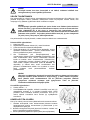
This machine needs two (2) 12V batteries. Please connect as shown
in Figure 4 on the right.
This machine can supply any of the following models:
a) Batteries(WET or GEL/ AGM) are already installed and can be
used at any time.
1. Check the battery. Through the connector (9) connect the battery to the
machine.
2. (Only applicable to AS430B and AS510B): Press down the on/off switch
(41). If the green light is on, it shows that the battery is ready for use.
If the amber or red light is on, it shows that the battery needs charging. (Please refer to the
section on maintenance for related procedures).
Figur
e 4
Figur
e 3

USER MANUAL
7
EN
GLISH
b) W
ithout batteries
1. Purchase similar battery (refer to the section on technical parameters). Information on the
selection of battery may be obtained from qualified battery agents.
2. Set the machine and the on-board charger (if equipped) according to the type of batteries (WET
or GEL/AGM). Also read the following paragraph for the way to install the battery.
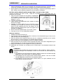
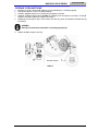
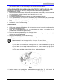
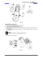
INSTALLING BATTERY AND SETTING BATTERY TYPE(WET OR GEL/AGM)
According to the battery type(WET or GEL/AGM) set the electric circuit board on the on-board charger.
The procedures are as follows:
1. Make sure the connector of the battery is disconnected. If the
machine is based on “AGM” battery at time of ex-factory, go
directly to Step 8; otherwise, complete Steps 2, 3, and 4.
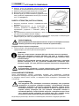
2. Take off draining hose (15)
3. If equipped with on-board charger, please take off the charge
wire from the reel.
4. Take off the control cover (5), and the screws of the battery
cover (10). Remove the screws on the PCB stand. The DIP
switch (B) for setting the battery model can be seen when
flipping over the PCB board. (See Figure 5)
5. Adjust the micro DIP switch (B) to the position of “WET”,
6. Complete Steps 3, 4 and 5 in reverse order.
Installing batteries
7. Disconnect the battery connector(9).
8. Open the recovery tanks cover (25) and check if the recovery tank is empty or not; if not, empty it
through draining hose (15).
9. Unscrew the squeegee fixed knob (16), take off the connector connecting the vacuum tube for
waste (11) to the squeegee, and then take off the squeegee.
10. Unscrew the screws of the battery cover (10) and remove the cover.
11. 11. Unscrew the connector of the squeegee drawing cord (12) connecting to the squeegee
bracket (19), and hang the squeegee drawing cord upwards.
12. Hang draining hose (15) and the vacuum tube for waste (11) upwards.
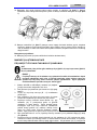
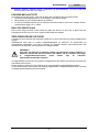
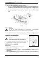
13. According to the size of the battery, push the fixation board in the battery box all the way inwards.
NOTE
The dimension of the battery must not exceed: H x W x H: 330mm x 170mm x 260mm.
According to the varying dimensions of batteries, the requirements for the selection of fixed
batteries are as follows:
1. For battery with length below 270mm, use 2 pieces of the fixation board (B, Figure 6)
and place them side by side inside the water tank battery;
2. For battery with length between 310mm-270mm, use 1 piece of the fixation board (B,
Figure 6) and place it in the water tank battery;
3. For battery with length between 330mm -310mm, there is no need for the fixation board
to fix the position.
Figure 6
Figure 5

USER MANUAL
8
EN
GLISH
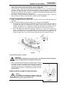
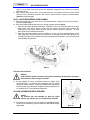
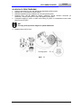
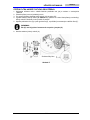
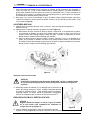
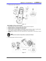
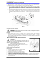
14. Inst
all the battery with specially made battery installation tools (A, Figure 7). After the battery is
installed, remove the battery installation tools, and install the battery fixation bracket (B, Figure 7).
Figure 7
15. Put
the battery connector (C, Figure 7) through the hole on the top of the battery box cover, put
the draining hose through the right hole of the battery box cover, fix the battery box cover with 4
screws, and then install the squeegee drawing cord, draining hose, and the squeegee
successively.
Charging the battery
16. To charge the battery (refer to the steps stated in the maintenance section).
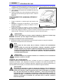
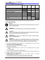
BEFORE MACHINE START-UP
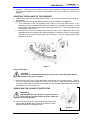
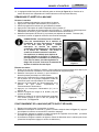
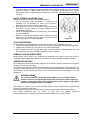
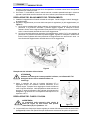
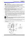
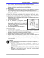
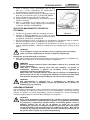
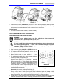
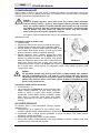
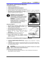
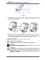
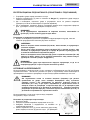
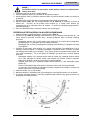
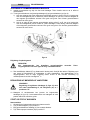
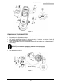
INSTALLING AND UNLOADING THE BRUSH / PAD-HOLDER
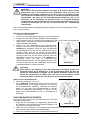
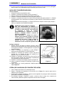
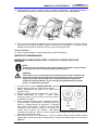
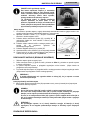
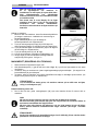
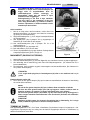
NOT
E
According to the type of floor to be cleaned, the machine may be installed with
brush (Figure8, A), or a pad-holder (Figure 8, B and C).
CAUTION !
When manually installing or unloading the brush/pad-holder, first check if all the
switches are in the off position and lift the squeegee off the floor, only after which
can the brush or pad-holder be worked on. Furthermore, please put on protective
gloves to avoid being cut by fragments.
1. (Only applicable to AS430B and AS510B): make sure the
switch (41) is at the disconnecting (O) condition.
2. Press down the handlebar (2) to lift the tank body (26).
3. Put the brush (A) or the pad-holder (B – C) under the case.
4. Use the handlebar (2) to lower the tank body (26) to come
into contact with the brush or pad-holder.
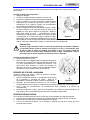
5. To install the brush/pad-holder automatically, turn the
power switch (41) to the “I” position and press down the
safety switch (1). Gently push the machine forward so as
to allow the belt wheel at the bottom of the tank body to
align with the brush or pad-holder which can then be
installed. Then release the safety switch. If necessary,
repeat this procedure until the brush/pad-holder is installed.
6. If Step 5 above proves to be difficult, use the manual
method by following the arrow head (D) to install the brush/pad-holder (as shown in Figure 8).
7. To automatically unload the brush/pad-holder, turn the power switch (41) to the “O” position. Use
the hand to hold the handlebar, and press the machine downwards until the guide wheel touches
the floor and the brush/pad-holder hangs in the air. Turn the power switch (41) to the “I” position,
and press down the safety switch to let the brush or pad-holder turn until the brush/pad-holder
drops to the floor.
Figur
e 8

USER MANUAL
9
EN
GLISH
8. If
Step No. 7 above proves to be difficult, use the manual method by turning the brush/pad-holder
in the direction opposite to the normal turning direction, and it can be taken off. (as shown in
Figure 8)
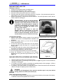
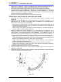
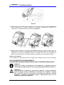
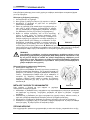
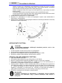
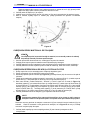
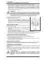
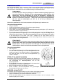
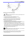
ADJUSTING THE BALANCE OF THE SQUEEGEE
9. Install the squeegee and turn it tight with the handle. Then connect the vacuum tube for waste to
the squeegee.
10. Adjust the squeegee through the adjusting handle (A) of the squeegee (see Figure 9).
1) If the mid-section of the rear squeegee strip, section B, has a gap with the floor or the
downward pressure is relatively light, adjust the handle in an anti-clockwise direction until the
whole length of the rear squeegee strip touches well with the floor. The front squeegee strip
should lightly touch the floor.
2) If the two ends of the rear squeegee strip, sections C and D, have a gap with the floor or the
downward pressure is relatively light, adjust the handle in a clockwise direction until the whole
length of the rear squeegee strip touches well with the floor. The front squeegee strip should
lightly touch the floor.
Figure 9
So
lution tank filling
CAUTION!
Only low foam, nonflammable detergents may be used. These detergents must be
suitable for the use of scrubbers.
11. Open the water inlet cover (27) and add water to solution tank. Do not overfill the tank. Filling up
to near the edge of the filter holder of the water inlet will suffice. When preparing the cleaning
solutions, please follow the dilution rates supplied by the chemical manufacture and the water
temperature must not exceed 40
0
C.
REGULATING THE VOLUME OF WATER FLOW
W
ARNING !
Regulating the ball valve handle (A, Figure 10) must be
done under the condition when the power switch (41)
is in the “O” position.
12. The volume of the water flow may be adjusted through the ball
valve handle (A, Figure 10) according to the amount of water
practically required for scrubbing the floor.
Figur
e 10

USER MANUAL
10
EN
GLISH
MACHINE START AND STOP
Starting the machine
1. Complete the preparatory steps as related above.
2. Press the power switch (41) to the “I” position.
3. Use the squeegee handle (41) to lower the squeegee.
4. Press the Vacuum pump switch (42) to the “I” position.
5. Press the water flow volume control switch (44) to the “I” position. (Work simultaneously with the
safety switch (1) to control the work of solenoid valve.)
6. Hold the safety switch (1) and push to move the machine. The brush (29) starts to rotate, and the
machine starts its cleaning job.
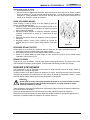
CONSULTATION:The way to push the machine
One of the characteristics of the machine is the
Installation of two safety switches on both sides
of handlebar. Each safety switch is capable of
controlling independently the operation of the
brush. In use, it facilitates the control of the
operation of the machine.
By experience, the method to move the
machine shown on right Figure 11 is more
suitable, the users feel more comfortable on
hands, it reduces work fatigue. So the users are
recommended to move the machine in this way
.
T
urning off the machine
7. When you have finished using the machine, first unload the brush/pad-holder (refer to the steps
related in the section on brush/pad-holder installation and
unloading)
8. Release the safety switch (1) to turn off the brush/pad-
holder and solenoid valve.
9. 9. Press the Vacuum pump switch (42) to the “O” position,
and the Vacuum pump will delay for 5 seconds before
stopping work.
10. 10. Press the water flow volume control switch (44) to the
“O” position to completely turn off the work of solenoid valve.
11. Press the power switch (41) to the “O” position.
12. Use the squeegee lifting handle (14) to lift the squeegee.
13. Grasp the handlebar (2) and gently tilt the machine
backward until the guide wheel (B) touches the floor. See
Figure 12.
MACHINE OPERATION (SCRUBBING AND DRYING)
1. S
tart the machine according to the description above.
2. Hold the safety switch (1) (according to the way shown in Figure 11), push to move the machine,
and start the cleaning job.
3. If necessary, turn off the machine, and adjust the regulating handle of the squeegee. (Refer to
the steps for adjusting the balance of the squeegee)
4. If necessary, turn off the machine, and adjust the volume of water flow with the ball valve handle.
(Refer to the steps of adjusting volume of water flow.)
CAUTION!
In order to avoid damaging the floor, when the machine stays in one place without
moving, please turn off the power switch (41).
Battery discharge during operation
5. It is only when the green warning light (38) is continuously lit that the power supply of the battery
is sufficient for the normal operation of the machine.
Figur
e 11
Figur
e 12

USER MANUAL
11
EN
GLISH
NOT
E
When all the four green lights (38) turn on, it shows that the battery is fully charged.
When only the last green light (38) is on, and begins to flash, suggest charging the
battery, for the machine will stop automatically after a few minutes.
After the last green light (38) turns off, and the red light (39 and 40) begins to flash,
the machine will stop automatically after a few seconds. (Refer to the steps related in
the maintenance section).
CAUTION!
Do not use the machine when the power supply of the battery is insufficient, so as
to avoid damaging the battery and shortening the life of the battery.
TANK EMPTYING
W
hen recovery tank is full, a float in the automatic float turn-off device (36) will block the inlet
connecting to the vacuum pump. Through a sudden increase of noise from the vacuum pump, it can
be considered that the vacuum pump is already overloaded and an immediate draining of the
wastewater is needed.
CAUTION!
If the vacuum pump is suddenly turned off (e.g. because the machine is suddenly
moved resulting in an activation of the float), and if a resumption of operation is
needed, please perform the following steps: press the power switch (41 and 42) to
turn off the power and the vacuum pump, and open the recovery tank cover (25) to
check if the float in the float filter has returned to the water surface. Then close
recovery tank cover (25), and press the power switch (41 and 42) to turn on the
power and the vacuum pump.
When the recovery tank is fully filled with wastewater, follow the following steps to drain it all.
Recovery tank emptying
1. Turn off the machine.
2. By using the squeegee handle (14), lift the squeegee.
3. Move the machine to a dedicated dump site.
4. Grasp the handlebar (2) and gently incline the machine
backward until the guide wheel touches the floor. (For
docking of the machine please refer to the procedures in the
stopping of the machine section.)
5. Take off the draining hose from the fixation clip, bend the top
end of draining hose (as shown in A, Figure 13), and then
open the cover of draining hose, lower draining hose to a low
level or on the ground to drain the water. Alternatively,
directly place draining hose to a low position or on the ground
to make the water outlet face downward (as show in B, Figure 13), and then twist open the water
draining lid to drain off the wastewater in the tank. After draining is completed, use pure water to
cleanse the inside of recovery tank.
CAUTION!
When draining the wastewater, the vacuum tube for waste must be folded or
lowered to a lower position (as shown in Figure 13 A or B), and then open the lid of
the vacuum tube for waste to drain the water. Do not make the outlet of the vacuum
tube for waste face upward to drain the water vertically. This is to avoid wastewater
spilling onto the operator.
Solution tank emptying
6. Complete Steps 1 to 4.
7. As shown in Figure 14, turn open the lid of Solution tank (A) anticlockwise along direction C, and
drain Solution tank completely. Use pure water to cleanse the inside of Solution tank. When work
is completed, turn tight the lid of Solution tank (A) clockwise in direction B.
Figure 13

USER MANUAL
12
EN
GLISH
AFTER USING THE MACHINE
W
hen work is done and before leaving the machine, completes the
following steps:
1. Follow the procedure as described in aforementioned section
about installing and unloading the brush/pad-holder, and take
off the brush/pad-holder.
2. Following the procedures described in related sections, drain
the water completely in Solution tank and recovery tank.
3. Complete the daily maintenance procedures (refer to the
section on maintenance).
4. Store the machine, including the brush/pad-holder and
squeegee, in a clean and dry place. The squeegee should be
lifted or taken off.
PERIODS OF INACTIVITY
If the machine is not to be used for more than 30 days, please treat
it in the following way:
1. Complete the necessary procedure that should be followed after the machine is used.
2. Disconnect the connector (9) connecting the battery and the machine.
3. In order not to damage the battery, and if the machine is not to be used for more than 3 months,
please charge the battery once every 3 months.
USING FOR THE FIRST TIME
A
fter using for the first 9 hours, please check all parts to make sure nothing has become loose or
damaged during operation, and check if there are any visible damages or leakage.
M
AINTENANCE AND CARE
The
service life and the maximum operation safety of the machine are assured by proper and timely
maintenance and care.
The following table provides a general maintenance plan for the machine. The time intervals of
maintenance are determined to a large extent by the working conditions of the machine. These time
intervals should be formulated by the personnel responsible for the maintenance.
WARNING!
Only after the power of the machine is turned off and the connection between the
machine and the battery is disconnected should these procedures be performed.
Before proceeding with any of the maintenance procedures, please study carefully
the related safety sections.
All maintenance in the plan or all additional maintenance must be done by qualified personnel or
authorised service centers.
This manual only relates the simplest and the most common maintenance procedures.
For any maintenance procedures other than those stated in this table of planned maintenance, please
refer to the maintenance manual of the service center.
Figure 14

USER MANUAL
13
EN
GLISH
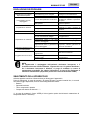
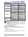
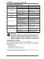
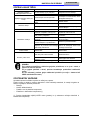
SCHEDULED MAINTENANCE TABLE
Proce
dure
Daily,
Machine
after use
Weekly Every
6 months
Ann
ually
Ch
arge battery
Clean s
queegee
Clean brush/pad-holder
Clean w
ater tank and float filter, inspect the
sealing strips of the water tank
Inspect
and change the squeegee strip
Clean
Solution filter
Clean
Vacuum pump filter
Inspect
liquid level of WET battery
Inspect
tightness of nuts and bolts
(1)
Inspect or change motor carbon brush of
brush/pad-holder
(2)
Inspect or change carbon brush of Vacuum pump
(2)
(1) It
should be done 9 hours after the machine starts working.
(2) These maintenance procedures must be done by an authorized VIPER Service Center.
BATTERY CHARGING
NOT
E
It is time to charge the battery when the amber or red warning light is lit up, or
every time when work is done.
CA
UTION!
Keep the battery in a fully charged condition in order to extend the service life of
the battery.
CA
UTION!
Once the power of the battery becomes insufficient, the battery must be charged
as soon as possible. Please check the charger at least once a week.
CA
UTION!
If an on-board charger is not equipped, please select a suitable external charger to
charge the battery.
W
ARNING!
Particular care must be taken when charging the battery because there may be
leakage of acid during the charging process. Battery acid is corrosive. If skin or
the eye accidentally comes into contact, please flush with plenty of water and see a
doctor.
1. Open the lid of recovery tank (25) and observe if recovery tank is empty or not. If it is not empty,
empty it through draining hose. (15).
2. Move the machine to a specified charging area.
3. Press the power switch (41) to the “O” position to turn off the machine.
4. Only applicable to WET water-addition battery
- Check the level of electrolyte inside the battery. If necessary, fill it up through the lid.
- Keep all lids open.
- If necessary, clean the top surface of the battery.
5. Select one of the following procedures to charge the battery according to the model of battery
being used.
To charge a battery with an external charger
6. Check, according to the related manual, if the external charger is appropriate. The output voltage
must be DC 24V.
7. Connect the battery connector to the external connector, and connect the external connector to
the mains.

USER MANUAL
14
EN
GLISH
8. W
hen charging is complete, connect the charging connector of the battery to the machine.
To charge a battery with an on-board charger (optional)
9. Take off the rubber lid at the end of the battery charging connector.
10. Connect the end of the battery charging connector with the mains with a charge connecting wire.
(Please note whether the input voltage of on-board charger is 220V – 240V and the output voltage
24V and frequency meet the requirements.) When the charger is connected to the mains, all
other functions will be cut off automatically. If the red warning light on the on-board charger
continues to light, it shows that the charger is charging the battery.
11. When the green warning light (47) is on, it shows that the battery charging process is complete.
12. When charging is complete, take off the connecting wire from the end of the battery charging
connector and the power supply, and put on the rubber lid.
13. Disconnect the charger wire from the power supply, and wind the wire on the reel (6).
NOT
E
If more information on on-board charger (35) is needed, please refer to related
manual.
SQUEEGEE CLEANING
NOT
E
In order to maintain the optimal effect of water Vacuum, the squeegee must be
kept clean, and the squeegee strip must remain in a good condition.
CA
UTION !
When cleaning the squeegee, it is recommended to put on protective gloves
because the squeegee may contain sharp fragments.
1. Move the machine to a flat and smooth surface.
2. Press the power switch (41) to the “O” position to turn off the machine.
3. Unscrew the fixed handle (16) of the squeegee; take off the connector connecting the Recovery
Vacuum tube of the squeegee, and take off the squeegee.
4. Use the squeegee lifting handle (14) to lift the squeegee support frame.
5. Clean the squeegee (Figure 15). Clean in particular the groove (A, Figure 15) and the dirt and
fragments on the Vacuum tube. Check if the front squeegee blade (C) and the rear squeegee
blade (D) are intact, and if there are broken edges and cracks. Change them if necessary (refer
to the steps in the following section).
6. Re-install the squeegee in the reverse order of the above.
SQUEEGEE BLADE CHECK AND REPLACEMENT
1. Follow
ing the methods related in the previous section clean the squeegee (Figure 15)
2. Check the edge (E, Figure 15) of the front squeegee blade and the edge (F) of the rear squeegee
blade (D). On the whole length, they should be on the same level. Otherwise, adjust their heights
through the following procedure.
- Loosen the clip (G) to let the rear squeegee blade (D) separate from the bracket (M) for the
adjustment of the position of the squeegee. After the adjustment, lock the clip once again.
- Loosen the screw on the handle (I) to adjust the front squeegee blade (C); tighten the handle
screw after adjustment.
3. Check if the front squeegee blade (C) and the rear squeegee blade (D) is intact and if there are
broken edges and cracks. If necessary, change them according to the following ways. Check the
front edge of the rear squeegee blade (J) whether it has been worn. If worn, it can be installed
upside down (the top edge is required to be intact). If the top edge is also worn, change it by
following the procedure below:
- Loosen the clip (G) to let the pressure blade separate from the bracket (M), take off the clip
bar (K), and then change or turn the rear squeegee blade (D) upside down. Re-install the rear
squeegee blade in the reverse order of taking it off.
- Loosen the handle screw (I) and take off the front clip bar (L), and then change the front
squeegee (C).
Re-install the front squeegee blade in the reverse order of taking it off.
After changing the squeegee blade (or installing upside down), adjust the level of the front and
rear squeegee blades in the procedures as described above.

USER MANUAL
15
EN
GLISH
4. Co
nnect the Vacuum tube (11) to the squeegee.
5. Install the squeegee and use the knob (16) to tighten it, and then connect the Vacuum tube to the
squeegee.
6. If necessary, adjust the squeegee through the adjusting handwheel (20) (refer to the procedures
for adjusting the balance of the squeegee).
Figure 15
BRUSH/POLISHING PAD CLEANING
CA
UTION!
When cleaning the brush/pad-holder, the wearing of protective gloves is
recommended because they may contain sharp fragments.
1. In the way as related in previous sections, take off the brush/pad-holder.
2. With the use of water and detergents, clean the brush/pad-holder.
3. Check the completeness and wearing condition of the bristles on the brush and, if necessary,
change the brush.
4. Check the wearing condition of the pad-holder and, if necessary, change the pad-holder.
WATER TANK AND FLOAT FILTER MESH CLEANING
1. Mov
e the machine to a dedicated dumping site.
2. Press the power switch (41) to the position “O” to turn off the machine.
3. Open recovery tank lid (A, Figure 16), and take off the float device (36) from recovery tank.
4. Use pure water to clean recovery tank lid (A), the tank (B and C), and the float filter support frame
(E). Through the Recovery tube (15), drain all the water from the water tank.
5. If necessary, following the symbols “Open” and “Close” as shown in Figure 16, open the bottom
lid (F) of the float filter and clean the float (D), float filter support frame (E), and the filter sponge (I).
After cleaning, fix the float onto the float filter support frame (E), and then align the mark groove (L)
of the bottom lid (F) of the float filter with the mark groove (L) of the float filter support frame (E).
Turn the bottom lid (F) of the float filter tight, and fix the filter sponge (I) onto the float filter support
frame (E), and then onto the Vacuum tube (M).
6. Check the soundness of the sealing ring (G) of the water tank lid.
NOT
E
The
sealing strip (G) of the water tank makes the water tank create a vacuum. It
must be completely sealed to be able to effectively suck the wastewater from the
floor.
If necessary, the sealing strip of the water tank (G) may be taken out from the groove (H) and
changed. When assembling a new water tank sealing strip, as shown in Figure 16 below, install
the connector to the middle section of the rear part.
7. Check if the receiving surface of the sealing strip (G) is intact and seals adequately.
8. Close recovery tank lid (A).

USER MANUAL
16
EN
GLISH
Figur
e 16
SOLUTION FILTER CLEANING
1. Drain all the water from Solution tank in the way as introduced in related sections.
2. Move the machine to a flat and smooth ground.
3. Press the power switch (41) to the “O” position to turn off the machine.
4. Turn off the draining ball valve (A, Figure 17) (located at the bottom of the machine, behind the
wheels). Position B ball valve open, and position C ball valve closed.
5. Take off the transparent lid (D), and then take off the filter (E), and install them onto the filter box
(F) after cleaning.
NOT
E
The filter (E) must be accurately installed onto the position of the projection (G).
6. Open the draining ball valve (A).
Figur
e 17
Filter
Mesh Mark

USER MANUAL
17
EN
GLISH
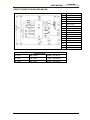
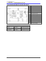
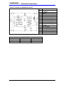
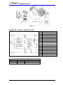
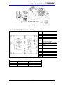
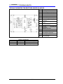
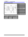
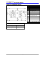
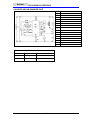
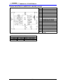
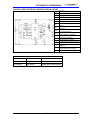
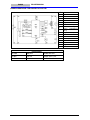
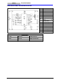
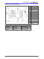
CIRCUIT FIGURE OF AS430B AND AS510B
B
AT
Battery
CH
Charger
EB1
Control circuit board
EB2
LED board
ES
Contactor
EV
Solenoid valve
F1
Brush motor fuse
F2
Vacuum motor fuse
F3
Control circuit board fuse
F4
Solenoid valve fuse
M1
Brush motor
M2
Vacuum motor
SW1
Power switch
S
W2
Brush motor switch
S
W3
Vacuum motor switch
SW4
Solenoid valve switch
HM
Timer (Only for AS510B)
CO
LORS CODES
R
D: Red BN: Brown BU/BK : Blue /Black
BU
: Blue YE: Yellow GN/BK: Green/Black
BK
: Black WH: White BN/BK: Brown/Black

USER MANUAL
18
EN
GLISH
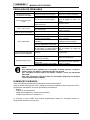
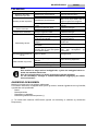
TR
OUBLESHOOTING
Break
down Probable Causes Remedies
Machine not working:
Indication light not on
Battery connector (9) not connected. Connect the battery connector
Batte
ry power already exhausted Charge the battery
Warning light (39 and 40)
flashing
Brush motor overloaded
Change to a soft brush to adapt to
the floor being cleaned
Other
matters jam the rotating of the
brush
Clear up the brush
Brush not working
Brush fuse trip off Reset
Bel
t slipping Check belt, adjust tension pulley
V
acuum motor not working Vacuum fuse trip off Reset
Inadequa
te Vacuum
Wastewater tank is full. Drain the water tank
Vacuum tube for waste and squeegee
not properly connected
Connect the Vacuum tube for waste
and the squeegee
Float f
ilter blocked or inlet blocked
Clean the float filter, check the float
ball
Sque
egee dirty or squeegee blade worn
and damaged
Clean and check the squeegee
Rec
overy tank lid not properly turned
on, or the sealing strip of the water tank
damaged
Refit on the lid properly, or change
the water tank sealing strip
Pure water s
upply to the brush
inadequate
Filter dirty. Clean the filter
Sque
egee leaving marks
Debris like fragments under the
squeegee blade
Remove the fragments
Sque
egee blade already worn, cracked,
brittle.
Change the squeegee blade
Balance of squeegee not adjusted Adjust the balance
NOT
E
If the machine is installed with the optional on-board charger, and when the on-
board charger is defective, the machine cannot be operated.
If the on-board charger is defective, please contact the authorised maintenance
center.
To find out more information, please refer to the maintenance manual (available at
any maintenance center of VIPER)
MACHINE DISPOSAL
Use
qualified crushing machine to destroy this machine.
Before destroying this machine, please take away and segregate the following materials which,
according to related laws and regulations, must be properly processed.
- Battery
- Brush/pad-holder
- Plastic hoses and plastic components
- Electrical and electronic components(*)
(*): Please contact the nearest VIPER Center (especially when scrapping of electrical and electronic
components is required).
Sayfa yükleniyor...
Sayfa yükleniyor...
Sayfa yükleniyor...
Sayfa yükleniyor...
Sayfa yükleniyor...
Sayfa yükleniyor...
Sayfa yükleniyor...
Sayfa yükleniyor...
Sayfa yükleniyor...
Sayfa yükleniyor...
Sayfa yükleniyor...
Sayfa yükleniyor...
Sayfa yükleniyor...
Sayfa yükleniyor...
Sayfa yükleniyor...
Sayfa yükleniyor...
Sayfa yükleniyor...
Sayfa yükleniyor...
Sayfa yükleniyor...
Sayfa yükleniyor...
Sayfa yükleniyor...
Sayfa yükleniyor...
Sayfa yükleniyor...
Sayfa yükleniyor...
Sayfa yükleniyor...
Sayfa yükleniyor...
Sayfa yükleniyor...
Sayfa yükleniyor...
Sayfa yükleniyor...
Sayfa yükleniyor...
Sayfa yükleniyor...
Sayfa yükleniyor...
Sayfa yükleniyor...
Sayfa yükleniyor...
Sayfa yükleniyor...
Sayfa yükleniyor...
Sayfa yükleniyor...
Sayfa yükleniyor...
Sayfa yükleniyor...
Sayfa yükleniyor...
Sayfa yükleniyor...
Sayfa yükleniyor...
Sayfa yükleniyor...
Sayfa yükleniyor...
Sayfa yükleniyor...
Sayfa yükleniyor...
Sayfa yükleniyor...
Sayfa yükleniyor...
Sayfa yükleniyor...
Sayfa yükleniyor...
Sayfa yükleniyor...
Sayfa yükleniyor...
Sayfa yükleniyor...
Sayfa yükleniyor...
Sayfa yükleniyor...
Sayfa yükleniyor...
Sayfa yükleniyor...
Sayfa yükleniyor...
Sayfa yükleniyor...
Sayfa yükleniyor...
Sayfa yükleniyor...
Sayfa yükleniyor...
Sayfa yükleniyor...
Sayfa yükleniyor...
Sayfa yükleniyor...
Sayfa yükleniyor...
Sayfa yükleniyor...
Sayfa yükleniyor...
Sayfa yükleniyor...
Sayfa yükleniyor...
Sayfa yükleniyor...
Sayfa yükleniyor...
Sayfa yükleniyor...
Sayfa yükleniyor...
Sayfa yükleniyor...
Sayfa yükleniyor...
Sayfa yükleniyor...
Sayfa yükleniyor...
Sayfa yükleniyor...
Sayfa yükleniyor...
Sayfa yükleniyor...
Sayfa yükleniyor...
Sayfa yükleniyor...
Sayfa yükleniyor...
Sayfa yükleniyor...
Sayfa yükleniyor...
Sayfa yükleniyor...
Sayfa yükleniyor...
Sayfa yükleniyor...
Sayfa yükleniyor...
Sayfa yükleniyor...
Sayfa yükleniyor...
Sayfa yükleniyor...
Sayfa yükleniyor...
Sayfa yükleniyor...
Sayfa yükleniyor...
Sayfa yükleniyor...
Sayfa yükleniyor...
Sayfa yükleniyor...
Sayfa yükleniyor...
Sayfa yükleniyor...
Sayfa yükleniyor...
Sayfa yükleniyor...
Sayfa yükleniyor...
Sayfa yükleniyor...
Sayfa yükleniyor...
Sayfa yükleniyor...
Sayfa yükleniyor...
Sayfa yükleniyor...
Sayfa yükleniyor...
Sayfa yükleniyor...
Sayfa yükleniyor...
Sayfa yükleniyor...
Sayfa yükleniyor...
Sayfa yükleniyor...
Sayfa yükleniyor...
Sayfa yükleniyor...
Sayfa yükleniyor...
Sayfa yükleniyor...
Sayfa yükleniyor...
Sayfa yükleniyor...
Sayfa yükleniyor...
Sayfa yükleniyor...
Sayfa yükleniyor...
Sayfa yükleniyor...
Sayfa yükleniyor...
Sayfa yükleniyor...
Sayfa yükleniyor...
Sayfa yükleniyor...
Sayfa yükleniyor...
Sayfa yükleniyor...
Sayfa yükleniyor...
Sayfa yükleniyor...
Sayfa yükleniyor...
Sayfa yükleniyor...
Sayfa yükleniyor...
Sayfa yükleniyor...
Sayfa yükleniyor...
Sayfa yükleniyor...
Sayfa yükleniyor...
Sayfa yükleniyor...
Sayfa yükleniyor...
Sayfa yükleniyor...
Sayfa yükleniyor...
Sayfa yükleniyor...
Sayfa yükleniyor...
Sayfa yükleniyor...
Sayfa yükleniyor...
Sayfa yükleniyor...
Sayfa yükleniyor...
Sayfa yükleniyor...
Sayfa yükleniyor...
Sayfa yükleniyor...
Sayfa yükleniyor...
Sayfa yükleniyor...
Sayfa yükleniyor...
Sayfa yükleniyor...
Sayfa yükleniyor...
Sayfa yükleniyor...
Sayfa yükleniyor...
Sayfa yükleniyor...
Sayfa yükleniyor...
Sayfa yükleniyor...
Sayfa yükleniyor...
Sayfa yükleniyor...
Sayfa yükleniyor...
Sayfa yükleniyor...
Sayfa yükleniyor...
Sayfa yükleniyor...
Sayfa yükleniyor...
Sayfa yükleniyor...
Sayfa yükleniyor...
Sayfa yükleniyor...
Sayfa yükleniyor...
Sayfa yükleniyor...
Sayfa yükleniyor...
Sayfa yükleniyor...
Sayfa yükleniyor...
Sayfa yükleniyor...
Sayfa yükleniyor...
Sayfa yükleniyor...
Sayfa yükleniyor...
Sayfa yükleniyor...
Sayfa yükleniyor...
Sayfa yükleniyor...
Sayfa yükleniyor...
Sayfa yükleniyor...
Sayfa yükleniyor...
Sayfa yükleniyor...
Sayfa yükleniyor...
Sayfa yükleniyor...
Sayfa yükleniyor...
Sayfa yükleniyor...
Sayfa yükleniyor...
Sayfa yükleniyor...
Sayfa yükleniyor...
Sayfa yükleniyor...
Sayfa yükleniyor...
Sayfa yükleniyor...
Sayfa yükleniyor...
Sayfa yükleniyor...
Sayfa yükleniyor...
Sayfa yükleniyor...
Sayfa yükleniyor...
Sayfa yükleniyor...
Sayfa yükleniyor...
Sayfa yükleniyor...
Sayfa yükleniyor...
Sayfa yükleniyor...
Sayfa yükleniyor...
Sayfa yükleniyor...
Sayfa yükleniyor...
Sayfa yükleniyor...
Sayfa yükleniyor...
Sayfa yükleniyor...
Sayfa yükleniyor...
Sayfa yükleniyor...
Sayfa yükleniyor...
Sayfa yükleniyor...
Sayfa yükleniyor...
Sayfa yükleniyor...
Sayfa yükleniyor...
Sayfa yükleniyor...
Sayfa yükleniyor...
Sayfa yükleniyor...
Sayfa yükleniyor...
Sayfa yükleniyor...
Sayfa yükleniyor...
Sayfa yükleniyor...
Sayfa yükleniyor...
Sayfa yükleniyor...
Sayfa yükleniyor...
Sayfa yükleniyor...
Sayfa yükleniyor...
Sayfa yükleniyor...
Sayfa yükleniyor...
Sayfa yükleniyor...
Sayfa yükleniyor...
Sayfa yükleniyor...
Sayfa yükleniyor...
Sayfa yükleniyor...
Sayfa yükleniyor...
Sayfa yükleniyor...
Sayfa yükleniyor...
Sayfa yükleniyor...
Sayfa yükleniyor...
Sayfa yükleniyor...
Sayfa yükleniyor...
Sayfa yükleniyor...
Sayfa yükleniyor...
Sayfa yükleniyor...
Sayfa yükleniyor...
Sayfa yükleniyor...
Sayfa yükleniyor...
Sayfa yükleniyor...
Sayfa yükleniyor...
Sayfa yükleniyor...
Sayfa yükleniyor...
Sayfa yükleniyor...
Sayfa yükleniyor...
Sayfa yükleniyor...
Sayfa yükleniyor...
Sayfa yükleniyor...
Sayfa yükleniyor...
Sayfa yükleniyor...
Sayfa yükleniyor...
Sayfa yükleniyor...
Sayfa yükleniyor...
Sayfa yükleniyor...
Sayfa yükleniyor...
Sayfa yükleniyor...
Sayfa yükleniyor...
Sayfa yükleniyor...
Sayfa yükleniyor...
Sayfa yükleniyor...
Sayfa yükleniyor...
Sayfa yükleniyor...
Sayfa yükleniyor...
Sayfa yükleniyor...
Sayfa yükleniyor...
Sayfa yükleniyor...
Sayfa yükleniyor...
Sayfa yükleniyor...
Sayfa yükleniyor...
Sayfa yükleniyor...
Sayfa yükleniyor...
Sayfa yükleniyor...
Sayfa yükleniyor...
Sayfa yükleniyor...
Sayfa yükleniyor...
Sayfa yükleniyor...
Sayfa yükleniyor...
Sayfa yükleniyor...
Sayfa yükleniyor...
Sayfa yükleniyor...
Sayfa yükleniyor...
Sayfa yükleniyor...
Sayfa yükleniyor...
Sayfa yükleniyor...
Sayfa yükleniyor...
Sayfa yükleniyor...
Sayfa yükleniyor...
Sayfa yükleniyor...
Sayfa yükleniyor...
Sayfa yükleniyor...
Sayfa yükleniyor...
Sayfa yükleniyor...
Sayfa yükleniyor...
Sayfa yükleniyor...
Sayfa yükleniyor...
Sayfa yükleniyor...
Sayfa yükleniyor...
Sayfa yükleniyor...
Sayfa yükleniyor...
Sayfa yükleniyor...
Sayfa yükleniyor...
Sayfa yükleniyor...
Sayfa yükleniyor...
Sayfa yükleniyor...
Sayfa yükleniyor...
Sayfa yükleniyor...
Sayfa yükleniyor...
Sayfa yükleniyor...
Sayfa yükleniyor...
Sayfa yükleniyor...
Sayfa yükleniyor...
Sayfa yükleniyor...
Sayfa yükleniyor...
Sayfa yükleniyor...
Sayfa yükleniyor...
Sayfa yükleniyor...
Sayfa yükleniyor...
Sayfa yükleniyor...
Sayfa yükleniyor...
Sayfa yükleniyor...
Sayfa yükleniyor...
Sayfa yükleniyor...
Sayfa yükleniyor...
Sayfa yükleniyor...
Sayfa yükleniyor...
Sayfa yükleniyor...
Sayfa yükleniyor...
Sayfa yükleniyor...
Sayfa yükleniyor...
Sayfa yükleniyor...
Sayfa yükleniyor...
Sayfa yükleniyor...
Sayfa yükleniyor...
-
 1
1
-
 2
2
-
 3
3
-
 4
4
-
 5
5
-
 6
6
-
 7
7
-
 8
8
-
 9
9
-
 10
10
-
 11
11
-
 12
12
-
 13
13
-
 14
14
-
 15
15
-
 16
16
-
 17
17
-
 18
18
-
 19
19
-
 20
20
-
 21
21
-
 22
22
-
 23
23
-
 24
24
-
 25
25
-
 26
26
-
 27
27
-
 28
28
-
 29
29
-
 30
30
-
 31
31
-
 32
32
-
 33
33
-
 34
34
-
 35
35
-
 36
36
-
 37
37
-
 38
38
-
 39
39
-
 40
40
-
 41
41
-
 42
42
-
 43
43
-
 44
44
-
 45
45
-
 46
46
-
 47
47
-
 48
48
-
 49
49
-
 50
50
-
 51
51
-
 52
52
-
 53
53
-
 54
54
-
 55
55
-
 56
56
-
 57
57
-
 58
58
-
 59
59
-
 60
60
-
 61
61
-
 62
62
-
 63
63
-
 64
64
-
 65
65
-
 66
66
-
 67
67
-
 68
68
-
 69
69
-
 70
70
-
 71
71
-
 72
72
-
 73
73
-
 74
74
-
 75
75
-
 76
76
-
 77
77
-
 78
78
-
 79
79
-
 80
80
-
 81
81
-
 82
82
-
 83
83
-
 84
84
-
 85
85
-
 86
86
-
 87
87
-
 88
88
-
 89
89
-
 90
90
-
 91
91
-
 92
92
-
 93
93
-
 94
94
-
 95
95
-
 96
96
-
 97
97
-
 98
98
-
 99
99
-
 100
100
-
 101
101
-
 102
102
-
 103
103
-
 104
104
-
 105
105
-
 106
106
-
 107
107
-
 108
108
-
 109
109
-
 110
110
-
 111
111
-
 112
112
-
 113
113
-
 114
114
-
 115
115
-
 116
116
-
 117
117
-
 118
118
-
 119
119
-
 120
120
-
 121
121
-
 122
122
-
 123
123
-
 124
124
-
 125
125
-
 126
126
-
 127
127
-
 128
128
-
 129
129
-
 130
130
-
 131
131
-
 132
132
-
 133
133
-
 134
134
-
 135
135
-
 136
136
-
 137
137
-
 138
138
-
 139
139
-
 140
140
-
 141
141
-
 142
142
-
 143
143
-
 144
144
-
 145
145
-
 146
146
-
 147
147
-
 148
148
-
 149
149
-
 150
150
-
 151
151
-
 152
152
-
 153
153
-
 154
154
-
 155
155
-
 156
156
-
 157
157
-
 158
158
-
 159
159
-
 160
160
-
 161
161
-
 162
162
-
 163
163
-
 164
164
-
 165
165
-
 166
166
-
 167
167
-
 168
168
-
 169
169
-
 170
170
-
 171
171
-
 172
172
-
 173
173
-
 174
174
-
 175
175
-
 176
176
-
 177
177
-
 178
178
-
 179
179
-
 180
180
-
 181
181
-
 182
182
-
 183
183
-
 184
184
-
 185
185
-
 186
186
-
 187
187
-
 188
188
-
 189
189
-
 190
190
-
 191
191
-
 192
192
-
 193
193
-
 194
194
-
 195
195
-
 196
196
-
 197
197
-
 198
198
-
 199
199
-
 200
200
-
 201
201
-
 202
202
-
 203
203
-
 204
204
-
 205
205
-
 206
206
-
 207
207
-
 208
208
-
 209
209
-
 210
210
-
 211
211
-
 212
212
-
 213
213
-
 214
214
-
 215
215
-
 216
216
-
 217
217
-
 218
218
-
 219
219
-
 220
220
-
 221
221
-
 222
222
-
 223
223
-
 224
224
-
 225
225
-
 226
226
-
 227
227
-
 228
228
-
 229
229
-
 230
230
-
 231
231
-
 232
232
-
 233
233
-
 234
234
-
 235
235
-
 236
236
-
 237
237
-
 238
238
-
 239
239
-
 240
240
-
 241
241
-
 242
242
-
 243
243
-
 244
244
-
 245
245
-
 246
246
-
 247
247
-
 248
248
-
 249
249
-
 250
250
-
 251
251
-
 252
252
-
 253
253
-
 254
254
-
 255
255
-
 256
256
-
 257
257
-
 258
258
-
 259
259
-
 260
260
-
 261
261
-
 262
262
-
 263
263
-
 264
264
-
 265
265
-
 266
266
-
 267
267
-
 268
268
-
 269
269
-
 270
270
-
 271
271
-
 272
272
-
 273
273
-
 274
274
-
 275
275
-
 276
276
-
 277
277
-
 278
278
-
 279
279
-
 280
280
-
 281
281
-
 282
282
-
 283
283
-
 284
284
-
 285
285
-
 286
286
-
 287
287
-
 288
288
-
 289
289
-
 290
290
-
 291
291
-
 292
292
-
 293
293
-
 294
294
-
 295
295
-
 296
296
-
 297
297
-
 298
298
-
 299
299
-
 300
300
-
 301
301
-
 302
302
-
 303
303
-
 304
304
-
 305
305
-
 306
306
-
 307
307
-
 308
308
-
 309
309
-
 310
310
-
 311
311
-
 312
312
-
 313
313
-
 314
314
-
 315
315
-
 316
316
-
 317
317
-
 318
318
-
 319
319
-
 320
320
-
 321
321
-
 322
322
-
 323
323
-
 324
324
-
 325
325
-
 326
326
-
 327
327
-
 328
328
-
 329
329
-
 330
330
-
 331
331
-
 332
332
-
 333
333
-
 334
334
-
 335
335
-
 336
336
-
 337
337
-
 338
338
-
 339
339
-
 340
340
-
 341
341
-
 342
342
-
 343
343
-
 344
344
-
 345
345
-
 346
346
-
 347
347
-
 348
348
-
 349
349
-
 350
350
-
 351
351
-
 352
352
-
 353
353
-
 354
354
-
 355
355
-
 356
356
-
 357
357
-
 358
358
-
 359
359
-
 360
360
-
 361
361
-
 362
362
-
 363
363
-
 364
364
-
 365
365
-
 366
366
-
 367
367
-
 368
368


Viper AS510B Kullanım kılavuzu
- Tip
- Kullanım kılavuzu
- Bu kılavuz aynı zamanda aşağıdakiler için de uygundur:
diğer dillerde
- español: Viper AS510B Manual de usuario
- français: Viper AS510B Manuel utilisateur
- italiano: Viper AS510B Manuale utente
- svenska: Viper AS510B Användarmanual
- čeština: Viper AS510B Uživatelský manuál
- polski: Viper AS510B Instrukcja obsługi
- Deutsch: Viper AS510B Benutzerhandbuch
- português: Viper AS510B Manual do usuário
- English: Viper AS510B User manual
- dansk: Viper AS510B Brugermanual
- русский: Viper AS510B Руководство пользователя
- suomi: Viper AS510B Ohjekirja
- Nederlands: Viper AS510B Handleiding
- română: Viper AS510B Manual de utilizare
İlgili makaleler
Diğer belgeler
-
 Nilfisk-Advance America ECOFLEX BR1100S Kullanım kılavuzu
-
Nilfisk-ALTO CR 1500 Kullanım kılavuzu
-
 Comet Spa CRS 66 BXT Kullanım kılavuzu
-
Comet CRS 75/85 BT Kullanım kılavuzu
-
-
-
Lavor Dynamic Kullanım kılavuzu
-
-
-
IPCEagle CT45 BT Kullanım kılavuzu

