
Scrubber User Manual
AS430C & AS510C
c
om
pany information:
www.vipercleaning.eu
info-eu@vipercleaning.com VF90015-EU
Rev.03

T
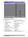
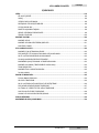
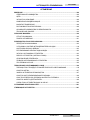
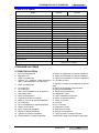
ABLE OF CONTENTS
ENGLISH USER MANUAL…………………………………………………
1-14
DEU
TSCH BETRIEBSANLEITUNG……………………………………….
15-29
FR
ANÇAİS MANUEL UTILISATEUR……………………………………….
30-44
NED
ERLANDS GEBRUIKERS HANDLEIDING………………………………..
45-58
IT
ALIANO MANUALE D’USO……………………………………………...
59-72
ESP
AÑOL ISTRUZIONI PER L’USO………………………………………
73-87
POR
TUGUÊS MANUAL DO UTILIZADOR…………………………………...
88-10
1
ΕΛΛΗΝΙΚΑ ΕΓΧΕΙΡΙΔΙΟ ΧΡΗΣΤΗ…………………………………….…….
102-1
16
TÜRKÇE KULLANIM KILAVUZU………………………………….….…
117-130
ČESKÝ UŽIVATELSKÝ MANUÁL……………………………………...
131-1
44
POLSKI INSTRUKCJA OBSŁUGI………………………………………
145-1
58
MAGYAR FELHASZNÁLÓI KÉZIKÖNYV………………………………..
159-172
ROMÂNĂ MANUALUL UTILIZATORULUI……………………………....
173-1
86
РУССКИЙ НСТРУКЦИЯ ПО ПРИМЕНЕНИЮ……………………..……
187-2
01
БЪЛГАРСКИ РЪКОВОДСТВО НА ПОТРЕБИТЕЛЯ……………………...
202-2
15
SLOVENŠČINA NAVODILA ZA UPORABO……………………………………
216-229
DA
NSK BRUGERMANUAL…………………………..……….………..
230-2
43
SVENSKA BRUKSANVISNING…………………………………………….
244-2
57
NORSK BRUKERHÅNDBOK……………………………………………
258-2
71
SUOMI KÄYTTÄJÄN OPAS...............………..……………………….
272-2
85

USE
R MANUAL
EN
GLISH
VF
90015-EU
1
T
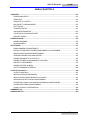
ABLE OF CONTENTS
INT
RODUCTION ....................................................................................................................................2
MANUAL CONTENTS ......................................................................................................................2
PURPOSE .........................................................................................................................................2
SPARE PARTS AND MAINTENANCE .............................................................................................2
CHANGES AND IMPROVEMENTS .................................................................................................2
SCOPE OF APPLICATION ...............................................................................................................2
IDENTIFICATION DATA....................................................................................................................2
UNPACKING/TRANSPORT ..............................................................................................................2
GENERAL SAFETY GUIDES ...........................................................................................................3
TECHNICAL DATA ............................................................................................................................4
MACHINE DESCRIPTION .....................................................................................................................4
MACHINE STRUCTURE ..................................................................................................................4
CONTROL PANEL ............................................................................................................................5
GUIDE FOR USE ...................................................................................................................................6
BEFORE MACHINE START-UP .......................................................................................................6
INSTALLING AND UNLOADING THE BRUSH / PAD-HOLDER .....................................................6
ADJUSTING THE BALANCE OF THE SQUEEGEE ........................................................................6
REGULATING THE VOLUME OF WATER FLOW ...........................................................................7
MACHINE START AND STOP ..........................................................................................................7
MACHINE OPERATION (SCRUBBING AND DRYING) ...................................................................8
TANK EMPTYING .............................................................................................................................8
AFTER USING THE MACHINE ........................................................................................................9
USING FOR THE FIRST TIME .........................................................................................................9
MAINTENANCE AND CARE .................................................................................................................9
SCHEDULED MAINTENANCE TABLE ..........................................................................................10
SQUEEGEE CLEANING ................................................................................................................10
SQUEEGEE BLADE CHECK AND REPLACEMENT ....................................................................10
BRUSH/POLISHING PAD CLEANING ........................................................................................... 11
WATER TANK AND FLOAT FILTER MESH CLEANING .............................................................. 11
SOLUTION FILTER CLEANING .....................................................................................................12
CIRCUIT FIGURE OF AS430C AND AS510C................................................................................13
TROUBLESHOOTING .........................................................................................................................14
MACHINE DISPOSAL .........................................................................................................................14

EN
GLISH
USE
R MANUAL
2
VF90015-EU
INTR
ODUCTION
NOT
E
The numbers in brackets refer to the related components shown in Machine
Description section.
MANUAL CONTENTS
This
manual is to provide the operator with the necessary information to use this machine properly
and safely. The information includes the technical data, safety, operation, storage, maintenance and
disposal of the machine. The operator and technicians with related qualifications must study this
manual carefully before commencing the operation and maintenance of this machine. Please contact
VIPER for any queries on the explanation of this manual or when further related information is needed.
PURPOSE
The
intention of this manual is to enable the operator and qualified technicians to accomplish the
maintenance of this machine.
The operator must not perform those operations that should only be performed by technicians. VIPER
will not be responsible for any damages caused by the violation of this rule.
SPARE PARTS AND MAINTENANCE
Al
l necessary operation, maintenance, and repair procedures must be performed by qualified
personnel or by the service centers of VIPER
Only Authorised spare parts and accessories should be used.
If service and ordering of spare parts or accessories are needed, please contact VIPER with the
model number of the machine and serial numbers.
CHANGES AND IMPROVEMENTS
VIPER makes continuous improvements on its products. VIPER reserves the right of changing and
improving the machines, and also the right of deciding by itself whether the benefits brought about by
the changes are applicable to the products already sold. All changes or extra accessories must be
agreed by VIPER and must be performed by the company.
SCOPE OF APPLICATION
This
scrubber is used in a domestic and industrial environment, and is suitable for the cleaning of
smooth and hard floors (scrubbing and waste water collection). It must be used by qualified
operators and in a safe environment. This scrubber can not be used for cleaning outdoors, on
carpets, and on relatively coarse floors.
IDENTIFICATION DATA
The m
achine model and serial number are marked on the plate (4).
This information is useful when requiring machine spare parts, Use the following table to write down
the machine identification data.
MACH
INE mode
......
............................................................
MACH
INE serial number
.....
..........................................
......
..
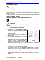
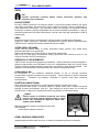
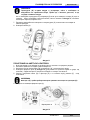
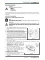
UNPACKING/TRANSPORT
Please
follow carefully the instructions on the package when unpacking.
On delivery, please inspect the packing and the machine to ensure no
damage has been done during transport. If there is any visible damage,
please keep the original form, and ask the carrier to confirm and fill out
a list of damages for compensation.
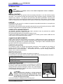
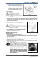
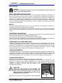
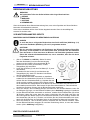
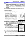
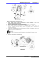
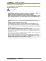
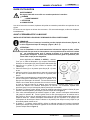
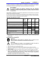
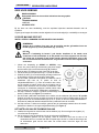
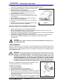
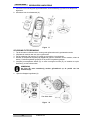
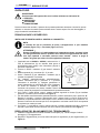
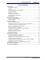
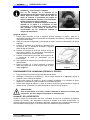
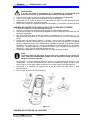
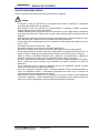
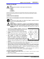
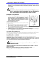
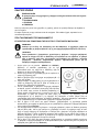
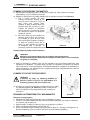
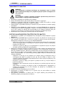
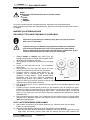
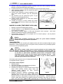
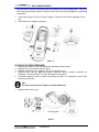
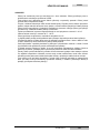
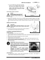
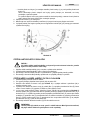
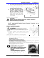
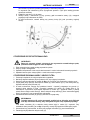
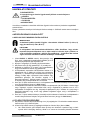
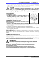
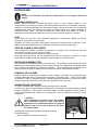
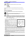
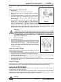
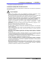
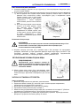
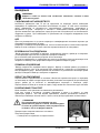
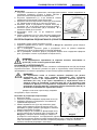
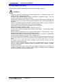
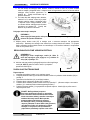
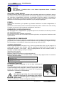
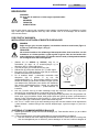
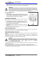
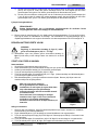
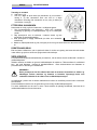
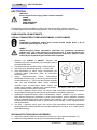
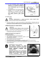
- CAUTION
When unpacking and unloading, or during moving the
machine across ground with steps, please take care to
avoid hitting the on/off switch regulating the water flow,
Part A in the figure on the right.
Check if the machine is equipped with the following items:

USE
R MANUAL
EN
GLISH
VF
90015-EU
3
T
echnical documents
- Scrubber User Manual
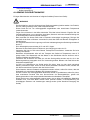
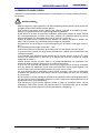
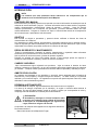
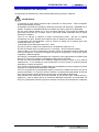
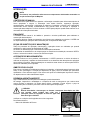
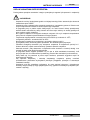
GENERAL SAFETY GUIDES
The
following are special warnings and notices on potential damages (personnel and machine):
WARNING!
- Machine may only be operated under the guidance of this manual. Only accessories approved by
VIPER should be used.
- This machine must be only used by duly trained or authorised personnel. Children or
inappropriate persons must not use this machine.
- When working near electrical parts, please do not wear any jewelry. Please take all precautionary
measures to avoid the hair, jewelry, and loose fitting clothes from being caught by any moving
parts of the machine.
- Please do not use this machine in particularly dirty areas. Do not wash the machine directly with
water. Do not let the machine come in touch with corrosive liquids.
- The temperature for storage and for working environment of the machine must be between 0 -
40
0
C.
- The humidity of air must be between 30% - 105%.
- Please do not use the machine on a slope with a gradient of more than 2%.
- In case of fire, please use dry powder fire extinguishers. Do not use liquid fire extinguishers.
- Particular attention should be paid when the machine is transported below 0
0
C.
The water tank
and the water in the hoses may freeze and cause serious damages to the machine.
- Use brushes and pads supplied with the machine and those specified in the User Manual. Using
other brushes or pads could reduce safety.
- In case of machine malfunction, please make sure that it is not caused by lack of maintenance. If
it is caused by other conditions, please seek the assistance of authorised personnel or the service
center.
- If it is confirmed that the spare parts must be replaced, please secure the genuine parts from
authorised dealers or agents.
- In order to ensure the safe and proper operation of the machine, please let authorised personnel
or the service center perform the scheduled maintenance according to the maintenance schedules
in the related sections of the manual.
- This machine must be properly disposed of because there may exist poisonous and hazardous
matters, and these matters must be disposed of by special centers in accordance with related laws
and regulations (please refer to machine disposal section).

EN
GLISH
USE
R MANUAL
4
VF90015-EU
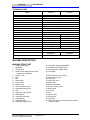
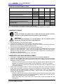
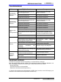
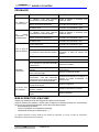
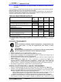
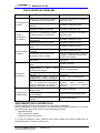
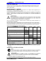
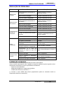
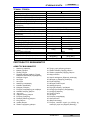
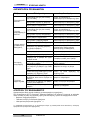
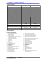
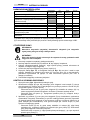
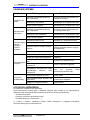
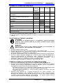
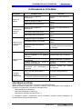
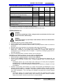
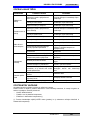
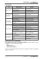
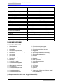
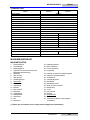
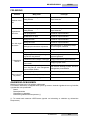
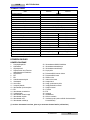
TECHNICAL DATA
Model AS430C AS510C
Mach
ine Height 980mm
So
lution tank capacity 50 litre
Re
covery tank capacity 50 litre
Dia
meter of transport wheel 200mm
Dia
meter of guide wheel 63.5mm
Power of vacuum system motor 400w
Maxi
mum gradient when working
2%(Max)
Sound pressure level at workstation
72dB(A)±3dB(A)
Ca
ble length 20m
V
acuum system circuit capacity
1200 mm H
2
O
Clean
ing width
430mm 510mm
Squ
eegee width
730mm 790mm
m
achine maximum length
1060mm 1100mm
Mach
ine width without squeegee
480mm 540mm
Brush dia
meter
430mm 510mm
We
ight with empty tanks
70kg 74kg
Gr
oss weight of the machine ready for use
120kg 124kg
Brush
motor power
750W
Brush s
peed
150rpm
Brush /
pad-holder Maximum pressure
32kg (Max) 35kg(Max)
Pac
king size (Lx W x H)
1200 x 610 x 1170mm
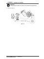
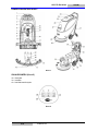
M
ACHINE DESCRIPTION
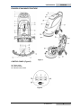
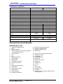
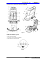
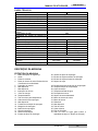
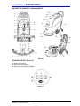
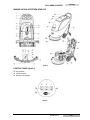
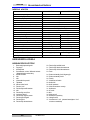
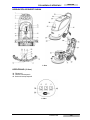
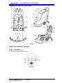
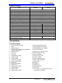
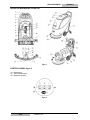
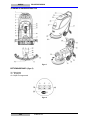
MACHINE STRUCTURE
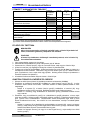
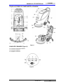
1. Sa
fety switch button 20. Squeegee adjusting handwheel
2. Handlebar 21. Squeegee rear support frame
3. Control panel 22. Squeegee front support frame
4. Serial number plate/Technical data
/ Conformity certification
23. Cup holder
5. Control cover 24. Recovery tank cover handle
6. N/A 25. Recovery tank cover
7. N/A 26. Tank body
8. Reset switch 27. Water inlet cover
9. Power cable 28. Brush deck
10. Battery cover 29. Brush / pad-holder
11. Vacuum tube for waste 30. Vacuum system motor
12. Squeegee drawing cord 31. Brush motor
13. N/A 32. 8” wheel
14. Squeegee lifting handle 33. N/A
15. Draining hose 34. Vacuum tube
16. Squeegee fixed knob 35. Electric box
17. Squeegee clip 36. Float filter
18. Squeegee blade 37. Water level tube ( to indicate amount of water
in
Solution tank)
19. Squeegee support frame

USE
R MANUAL
EN
GLISH
VF
90015-EU
5
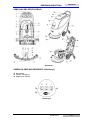
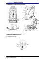
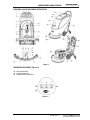
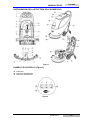
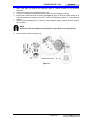
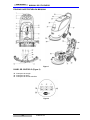
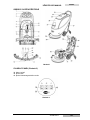
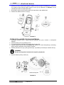
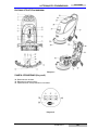
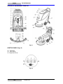
FIGURES OF MACHINE STRUCTURE
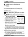
CONTROL PANEL (Figure2)
38. Power
switch
39. Vacuum switch
40. Solenoid valve switch
Figur
e 2
Figure 1

EN
GLISH
USE
R MANUAL
6
VF90015-EU
GUIDE FOR USE
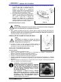
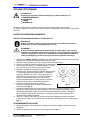
WARNING
On certain parts of the machine are pasted some indicative signs:
- DANGER
- WARNING
- CAUTION
- CONSULTATION
When reading this manual, the operator must pay particular attentions to the symbols on these signs.
Under no circumstances shall these signs be covered. If they are damaged, please replace
immediately.
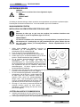
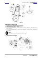
BEFORE MACHINE START-UP
INS
TALLING AND UNLOADING THE BRUSH / PAD-HOLDER
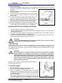
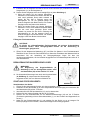
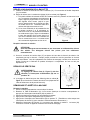
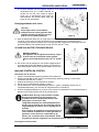
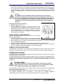
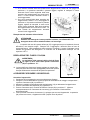
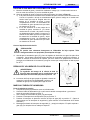
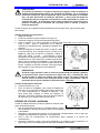
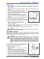
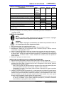
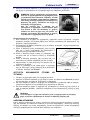
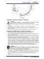
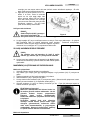
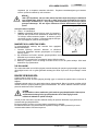
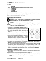
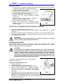
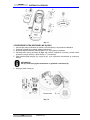
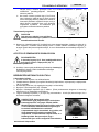
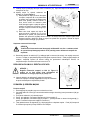
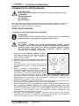
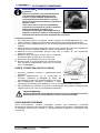
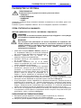
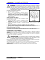
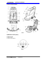
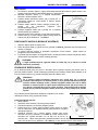
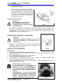
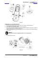
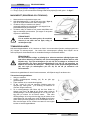
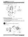
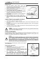
NOT
E
According to the type of floor to be cleaned, the machine may be installed with
brush (Figure3, A), or a pad-holder (Figure 3, B and C).
CAUTION !
When manually installing or unloading the brush/pad-holder, first check if all the
switches are in the off position and lift the squeegee off the floor, only after which
can the brush or pad-holder be worked on. Furthermore, please put on protective
gloves to avoid being cut by fragments.
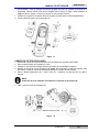
1. (Only applicable to AS430C and AS510C): make sure the
power cable (9) disconnecting the power supply and the
power switch (38) is at the disconnecting (O) condition.
2. Press down the handlebar (2) to lift the tank body (26).
3. Put the brush (A) or the pad-holder (B – C) under the case.
4. Use the handlebar (2) to lower the tank body (26) to come
into contact with the brush or pad-holder.
5. To install the brush/pad-holder automatically, turn the
power switch (38) to the “I” position and press down the
safety switch (1). Gently push the machine forward so as
to allow the belt wheel at the bottom of the tank body to
align with the brush or pad-holder which can then be
installed. Then release the safety switch. If necessary, repeat this procedure until the brush/pad-
holder is installed.
6. If Step 5 above proves to be difficult, use the manual method by following the arrow head (D) to
install the brush/pad-holder (as shown in Figure 3).
7. To automatically unload the brush/pad-holder, turn the power switch (38) to the “O” position. Use
the hand to hold the handlebar, and press the machine downwards until the guide wheel touches
the floor and the brush/pad-holder hangs in the air. Turn the power switch (38) to the “I” position,
and press down the safety switch to let the brush or pad-holder turn until the brush/pad-holder
drops to the floor.
8. If Step No. 7 above proves to be difficult, use the manual method by turning the brush/pad-holder
in the direction opposite to the normal turning direction, and it can be taken off. (as shown in
Figure 3)
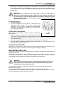
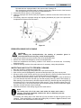
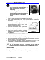
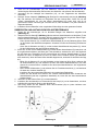
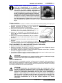
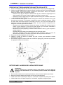
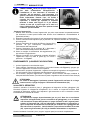
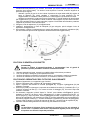
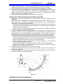
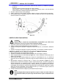
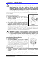
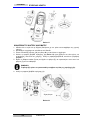
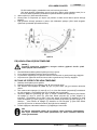
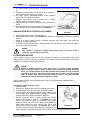
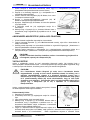
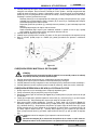
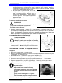
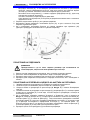
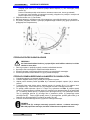
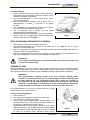
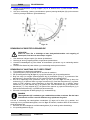
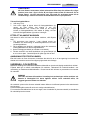
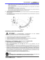
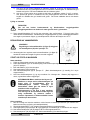
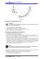
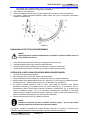
ADJUSTING THE BALANCE OF THE SQUEEGEE
9. Inst
all the squeegee and turn it tight with the handle (16). Then connect the vacuum tube (11) for
waste to the squeegee.
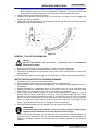
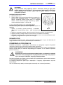
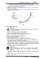
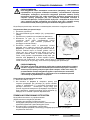
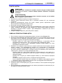
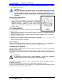
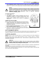
10. Adjust the squeegee through the adjusting handle (A) of the squeegee (see Figure 4).
1) If the mid-section of the rear squeegee strip, section B, has a gap with the floor or the
downward pressure is relatively light, adjust the handle in an anti-clockwise direction until the
whole length of the rear squeegee strip touches well with the floor. The front squeegee strip
should lightly touch the floor.
Figur
e 3

USE
R MANUAL
EN
GLISH
VF
90015-EU
7
2) If
the two ends of the rear squeegee strip,
sections C and D, have a gap with the floor
or the downward pressure is relatively light,
adjust the handle in a clockwise direction
until the whole length of the rear squeegee
strip touches well with the floor. The front
squeegee strip should lightly touch the floor.
Solution tank filling
CAUTION!
Only low foam, nonflammable
detergents may be used. These
detergents must be suitable for the use
of scrubbers.
11. Open the water inlet cover (27) and add water to solution tank. Do not overfill the tank. Filling up
to near the edge of the filter holder of the water inlet will suffice. When preparing the cleaning
solutions, please follow the dilution rates supplied by the chemical manufacture and the water
temperature must not exceed 40
0
C.
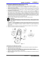
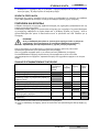
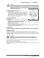
REGULATING THE VOLUME OF WATER FLOW
W
ARNING !
Regulating the ball valve handle (A, Figure 5) must
be done under the condition when the power switch
(38) is in the “O” position.
12. The volume of the water flow may be adjusted through the ball
valve handle (A, Figure 5) according to the amount of water
practically required for scrubbing the floor.
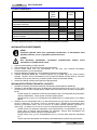
MACHINE START AND STOP
S
tarting the machine
1. Complete the preparatory steps as related above.
2. Connect the power cable (9) to a corresponding voltage power supply, and press the power switch
(38) to the “I” position.
3. Use the squeegee handle (14) to lower the squeegee.
4. Press the Vacuum switch (39) to the “I” position.
5. Press the water flow volume control switch (40) to the “I” position. (Work simultaneously with the
safety switch (1) to control the work of solenoid valve.)
6. Hold the safety switch (1) and push to move the machine. The brush (29) starts to rotate, and the
machine starts its cleaning job.
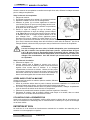
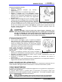
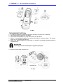
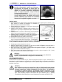
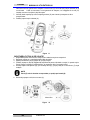
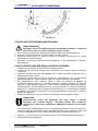
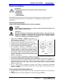
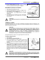
CONSULTATION:The way to push the machine
One of the characteristics of the machine is the
Installation of two safety switches on both sides of
handlebar. Each safety switch is capable of
controlling independently the operation of the
brush. In use, it facilitates the control of the
operation of the machine.
By experience, the method to move the machine
shown on right Figure 6 is more suitable, the users
feel more comfortable on hands, it reduces work
fatigue. So the users are recommended to move
the machine in this way
.
Figure 5
Figur
e 4
Figur
e 6

EN
GLISH
USE
R MANUAL
8
VF90015-EU
Figur
e
8
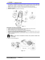
T
urning off the machine
7. When you have finished using the machine, first unload the brush/pad-holder (refer to the steps
related in the section on brush/pad-holder installation and
unloading)
8. Release the safety switch (1) to turn off the brush/pad-holder
and solenoid valve.
9. 9. Press the Vacuum pump switch (39) to the “O” position,
and the Vacuum pump will delay for 5 seconds before
stopping work.
10. 10. Press the water flow volume control switch (40) to the “O”
position to completely turn off the work of solenoid valve.
11. Press the power switch (38) to the “O” position. And
disconnecting the power cable (9) from the power supply.
12. Use the squeegee lifting handle (14) to lift the squeegee.
13. Grasp the handlebar (2) and gently tilt the machine backward
until the guide wheel (B) touches the floor. See Figure 7.
MACHINE OPERATION (SCRUBBING AND DRYING)
1. S
tart the machine according to the description above.
2. Hold the safety switch (1) (according to the way shown in Figure 6), push to move the machine,
and start the cleaning job.
3. If necessary, turn off the machine, and adjust the regulating handle of the squeegee. (Refer to
the steps for adjusting the balance of the squeegee)
4. If necessary, turn off the machine, and adjust the volume of water flow with the ball valve handle.
(Refer to the steps of adjusting volume of water flow.)
CAUTION!
In order to avoid damaging the floor, when the machine stays in one place without
moving, please turn off the power switch (38).
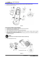
TANK EMPTYING
W
hen recovery tank is full, a float in the automatic float turn-off device (36) will block the inlet
connecting to the vacuum pump. Through a sudden increase of noise from the vacuum pump, it can
be considered that the vacuum pump is already overloaded and an immediate draining of the
wastewater is needed.
CAUTION!
If the vacuum motor is suddenly turned off (e.g. because the machine is suddenly
moved resulting in an activation of the float), and if a resumption of operation is
needed, please perform the following steps: press the power switch (38 and 39) to
turn off the power and the vacuum motor, and open the recovery tank cover (25) to
check if the float in the float filter has returned to the water surface. Then close
recovery tank cover (25), and press the power switch (38 and 39) to turn on the
power and the vacuum motor.
When the recovery tank is fully filled with wastewater, follow the
following steps to drain it all.
Recovery tank emptying
1. Turn off the machine.
2. By using the squeegee handle (14), lift the squeegee.
3. Move the machine to a dedicated dump site.
4. Grasp the handlebar (2) and gently incline the machine
backward until the guide wheel touches the floor. (For docking
of the machine please refer to the procedures in the stopping of
the machine section.)
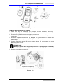
5. Take off the draining hose from the fixation clip, bend the top
end of draining hose (as shown in A, Figure 8), and then open
the cover of draining hose, lower draining hose to a low level or on the ground to drain the water.
Figur
e 7

USE
R MANUAL
EN
GLISH
VF
90015-EU
9
Al
ternatively, directly place draining hose to a low position or on the ground to make the water
outlet face downward (as show in B, Figure 8), and then twist open the water draining lid to drain
off the wastewater in the tank. After draining is completed, use pure water to cleanse the inside of
recovery tank.
CAUTION!
When draining the wastewater, the vacuum tube for waste must be folded or
lowered to a lower position (as shown in Figure 8 A or B), and then open the lid of
the vacuum tube for waste to drain the water. Do not make the outlet of the vacuum
tube for waste face upward to drain the water vertically. This is to avoid wastewater
spilling onto the operator.
Solution tank emptying
6. Complete Steps 1 to 4.
7. As shown in Figure 9, turn open the lid of Solution tank (A)
anticlockwise along direction C, and drain Solution tank
completely. Use pure water to cleanse the inside of Solution
tank. When work is completed, turn tight the lid of Solution tank
(A) clockwise in direction B.
AFTER USING THE MACHINE
W
hen work is done and before leaving the machine, completes the
following steps:
1. Follow the procedure as described in aforementioned section
about installing and unloading the brush/pad-holder, and take off the brush/pad-holder.
2. Following the procedures described in related sections, drain the water completely in Solution
tank and recovery tank.
3. Complete the daily maintenance procedures (refer to the section on maintenance).
4. Store the machine, including the brush/pad-holder and squeegee, in a clean and dry place. The
squeegee should be lifted or taken off.
USING FOR THE FIRST TIME
A
fter using for the first 9 hours, please check all parts to make sure nothing has become loose or
damaged during operation, and check if there are any visible damages or leakage.
M
AINTENANCE AND CARE
The
service life and the maximum operation safety of the machine are assured by proper and timely
maintenance and care.
The following table provides a general maintenance plan for the machine. The time intervals of
maintenance are determined to a large extent by the working conditions of the machine. These time
intervals should be formulated by the personnel responsible for the maintenance.
WARNING!
Only after the power of the machine is disconnected should these procedures be
performed. Before proceeding with any of the maintenance procedures, please
study carefully the related safety sections.
All maintenance in the plan or all additional maintenance must be done by qualified personnel or
authorised service centers.
This manual only relates the simplest and the most common maintenance procedures.
For any maintenance procedures other than those stated in this table of planned maintenance, please
refer to the maintenance manual of the service center.
Figur
e 9

EN
GLISH
USE
R MANUAL
10
VF90015-EU
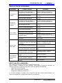
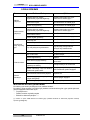
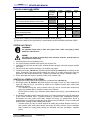
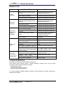
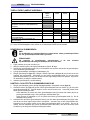
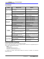
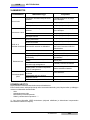
SCHEDULED MAINTENANCE TABLE
Proce
dure
Daily,
Machine
after use
Weekly Every
6 months
Ann
ually
Clean s
queegee
Clean br
ush/pad-holder
Clean w
ater tank and float filter, inspect the
sealing strips of the water tank
Inspect
and change the squeegee strip
Clean
Solution filter
Clean Vacuum motor filter
Inspect
tightness of nuts and bolts
(1)
Inspect
or change motor carbon brush of
brush/pad-holder
(2)
Inspect
or change carbon brush of Vacuum motor
(2)
(1) It
should be done 9 hours after the machine starts working.
(2) These maintenance procedures must be done by an authorized VIPER Service Center.
SQUEEGEE CLEANING
NOT
E
In order to maintain the optimal effect of water Vacuum, the squeegee must be
kept clean, and the squeegee strip must remain in a good condition.
CA
UTION !
When cleaning the squeegee, it is recommended to put on protective gloves
because the squeegee may contain sharp fragments.
1. Move the machine to a flat and smooth surface.
2. Press the power switch (38) to the “O” position to turn off the machine.
3. Unscrew the fixed handle (16) of the squeegee; take off the connector connecting the Recovery
Vacuum tube of the squeegee, and take off the squeegee.
4. Use the squeegee lifting handle (14) to lift the squeegee support frame.
5. Clean the squeegee (Figure 10). Clean in particular the groove (A, Figure 10) and the dirt and
fragments on the Vacuum tube. Check if the front squeegee blade (C) and the rear squeegee
blade (D) are intact, and if there are broken edges and cracks. Change them if necessary (refer to
the steps in the following section).
6. Re-install the squeegee in the reverse order of the above.
SQUEEGEE BLADE CHECK AND REPLACEMENT
1. Follow
ing the methods related in the previous section clean the squeegee (Figure 10)
2. Check the edge (E, Figure 10) of the front squeegee blade and the edge (F) of the rear squeegee
blade (D). On the whole length, they should be on the same level. Otherwise, adjust their heights
through the following procedure.
- Loosen the clip (G) to let the rear squeegee blade (D) separate from the bracket (M) for the
adjustment of the position of the squeegee. After the adjustment, lock the clip once again.
- Loosen the screw on the handle (I) to adjust the front squeegee blade (C); tighten the handle
screw after adjustment.
3. Check if the front squeegee blade (C) and the rear squeegee blade (D) is intact and if there are
broken edges and cracks. If necessary, change them according to the following ways. Check the
front edge of the rear squeegee blade (J) whether it has been worn. If worn, it can be installed
upside down (the top edge is required to be intact). If the top edge is also worn, change it by
following the procedure below:
- Loosen the clip (G) to let the pressure blade separate from the bracket (M), take off the clip bar
(K), and then change or turn the rear squeegee blade (D) upside down. Re-install the rear
squeegee blade in the reverse order of taking it off.
- Loosen the handle screw (I) and take off the front clip bar (L), and then change the front
squeegee (C).

USE
R MANUAL
EN
GLISH
VF
90015-EU
1
1
Re-in
stall the front squeegee blade in the reverse order of taking it off.
After changing the squeegee blade (or installing upside down), adjust the level of the front and
rear squeegee blades in the procedures as described above.
4. Connect the Vacuum tube (11) to the squeegee.
5. Install the squeegee and use the knob (16) to tighten it, and then connect the Vacuum tube to the
squeegee.
6. If necessary, adjust the squeegee through the adjusting handwheel (20) (refer to the procedures
for adjusting the balance of the squeegee).
Figure 10
BRUSH/POLISHING PAD CLEANING
CA
UTION!
When cleaning the brush/pad-holder, the wearing of protective gloves is
recommended because they may contain sharp fragments.
1. In the way as related in previous sections, take off the brush/pad-holder.
2. With the use of water and detergents, clean the brush/pad-holder.
3. Check the completeness and wearing condition of the bristles on the brush and, if necessary,
change the brush.
4. Check the wearing condition of the pad-holder and, if necessary, change the pad-holder.
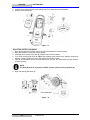
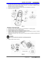
WATER TANK AND FLOAT FILTER MESH CLEANING
1. Mov
e the machine to a dedicated dumping site.
2. Press the power switch (38) to the position “O” to turn off the machine.
3. Open recovery tank lid (A, Figure 11), and take off the float device (36) from recovery tank.
4. Use pure water to clean recovery tank lid (A), the tank (B and C), and the float filter support frame
(E). Through the Recovery tube (15), drain all the water from the water tank.
5. If necessary, following the symbols “Open” and “Close” as shown in Figure 11, open the bottom lid
(F) of the float filter and clean the float (D), float filter support frame (E), and the filter sponge (I).
After cleaning, fix the float onto the float filter support frame (E), and then align the mark groove (L)
of the bottom lid (F) of the float filter with the mark groove (L) of the float filter support frame (E).
Turn the bottom lid (F) of the float filter tight, and fix the filter sponge (I) onto the float filter support
frame (E), and then onto the Vacuum tube (M).
6. Check the soundness of the sealing ring (G) of the water tank lid.
NOT
E
The
sealing strip (G) of the water tank makes the water tank create a
vacuum. It must be completely sealed to be able to effectively suck the
wastewater from the floor.
If necessary, the sealing strip of the water tank (G) may be taken out from the groove (H) and
changed. When assembling a new water tank sealing strip, as shown in Figure 11 below, install
the connector to the middle section of the rear part.

EN
GLISH
USE
R MANUAL
12
VF90015-EU
7. Ch
eck if the receiving surface of the sealing strip (G) is intact and seals adequately.
8. Close recovery tank lid (A).
Figure
11
SOLUTION FILTER CLEANING
1. Dra
in all the water from Solution tank in the way as introduced in related sections.
2. Move the machine to a flat and smooth ground.
3. Press the power switch (38) to the “O” position to turn off the machine.
4. Turn off the draining ball valve (A, Figure 12) (located at the bottom of the machine, behind the
wheels). Position B ball valve open, and position C ball valve closed.
5. Take off the transparent lid (D), and then take off the filter (E), and install them onto the filter box
(F) after cleaning.
NOT
E
The filter (E) must be accurately installed onto the position of the projection (G).
6. Open the draining ball valve (A)
Figur
e 12
Filter
Mesh Mark

USE
R MANUAL
EN
GLISH
VF
90015-EU
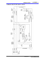
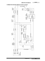
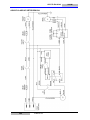
13
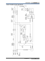
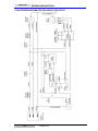
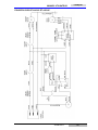
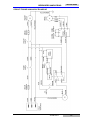
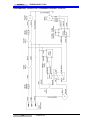
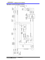
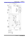
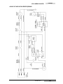
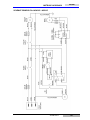
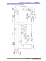
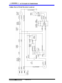
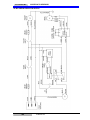
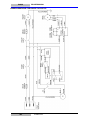
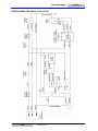
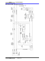
CIRCUIT FIGURE OF AS430C AND AS510C

EN
GLISH
USE
R MANUAL
14
VF90015-EU
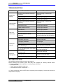
TR
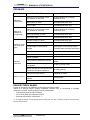
OUBLESHOOTING
Breakdown Probable Causes Remedies
Mach
ine not
working
The wiring not connected correctly or
bad wiring
Check the wiring or contact Viper
Distributor
Bad br
ush motor Contact Viper Distributor
Ca
rbon brush worn out Contact Viper Distributor
Vac
uum motor
not working
The wiring not connected correctly or
bad wiring
Check the wiring or contact Viper
Distributor
Bad vacuum motor Contact Viper Distributor
Ca
rbon brushes worn out Contact Viper Distributor
Li
ttle or no
solution flow
Bad ball valve Contact Viper Distributor
Bad s
olution valve Contact Viper Distributor
Ball valve position in need of
adjustment
When ball valve is in horizontal position,
the amount of solution flow is maximum
Fil
ter dirty.
Clean th
e filter
Inadeq
uate
Vacuum
Wastewater tank is full. Drain the water tank
Vac
uum tube for waste and squeegee
not properly connected
Connect the Vacuum tube for waste and
the squeegee
Fl
oat filter blocked or inlet blocked Clean the float filter, check the float ball
Squ
eegee dirty or squeegee blade
worn and damaged
Clean and check the squeegee
Re
covery tank lid not properly turned
on, or the sealing strip of the water
tank damaged
Refit on the lid properly, or change the
water tank sealing strip
Squ
eegee
leaving marks
Debris like fragments under the
squeegee blade
Remove the fragments
Squ
eegee blade already worn,
cracked, brittle.
Change the squeegee blade
Ba
lance of squeegee not adjusted Adjust the balance
M
ACHINE DISPOSAL
Use
qualified crushing machine to destroy this machine.
Before destroying this machine, please take away and segregate the following materials which,
according to related laws and regulations, must be properly processed.
- Brush/pad-holder
- Plastic hoses and plastic components
- Electrical and electronic components(*)
(*): Please contact the nearest VIPER Center (especially when scrapping of electrical and electronic
components is required).

BEDIENUNGSANLEITUNG
VF
90015-EU
15
DEU
TSC
H
INHALTSVERZEİCHNİS
EIN
LEITUNG ....................................................................................................................................... 16
INHALT DER BEDIENUNGSANLEITUNG .................................................................................... 16
ZWECK .......................................................................................................................................... 16
ERSATZTEILE UND WARTUNG ................................................................................................... 16
ÄNDERUNGEN UND VERBESSERUNGEN ................................................................................ 16
ANWENDUNGSBEREICH ............................................................................................................ 16
AUSPACKEN/TRANSPORT .......................................................................................................... 16
ALLGEMEINE SICHERHEITSHINWEISE ..................................................................................... 17
TECHNISCHE DATEN ................................................................................................................... 18
GERÄTEBESCHREIBUNG ................................................................................................................ 18
AUFBAU DES GERÄTS ................................................................................................................ 18
ÜBERBLICK ÜBER DAS BEDIENFELD ....................................................................................... 19
BEDIENUNGSANLEITUNG ............................................................................................................... 20
VOR INBETRIEBNAHME DES GERÄTS ...................................................................................... 20
MONTIEREN UND ENTFERNEN DER BÜRSTEN/PAD-HALTERUNG....................................... 20
EINSTELLEN DER SAUGLEISTE................................................................................................. 20
REGULIERUNG DES WASSERDURCHFLUSSES ...................................................................... 21
START UND STOPP DES GERÄTS ............................................................................................. 21
EINSATZ DES GERÄTS (SCHEUERN UND TROCKNEN) .......................................................... 22
TANK ENTLEEREN ....................................................................................................................... 22
NACH DEM EINSATZ DES GERÄTS ........................................................................................... 23
VOR DER ERSTEN VERWENDUNG ........................................................................................... 24
WARTUNG UND PFLEGE .................................................................................................................. 24
TABELLE DER PLANMÄSSIGEN WARTUNGSARBEITEN ......................................................... 24
REINIGEN DES ABSTREIFERS ................................................................................................... 24
ÜBERPRÜFEN UND AUSTAUSCHEN DES ABSTREIFERBANDS ............................................. 25
REINIGEN VON BÜRSTE/POLIERPAD ....................................................................................... 26
REINIGEN DES SCHMUTZWASSERTANKS UND DES SCHWIMM FILTERSIEBS .................. 26
REINIGEN DES FRISCHWASSERTANKS ................................................................................... 27
SCHALTKREISDIAGRAMM FÜR DEN AS430C UND AS510C ................................................... 28
FEHLERBEHEBUNG .......................................................................................................................... 29
GERÄTEENTSORGUNG .................................................................................................................... 29

BEDIENUNGSANLEITUNG
16
VF
90015-EU
DEU
TSC
H
EINL
EITUNG
HIN
WEIS
Die Zahlen in Klammern beziehen sich auf die im Abschnitt "Beschreibung des
Geräts" dargestellten Komponenten.
INHALT DER BEDIENUNGSANLEITUNG
Diese
s Handbuch dient dazu, den Anwender mit den notwendigen Informationen auszurüsten, um
dieses Gerät richtig und sicher nutzen zu können. Die Informationen beinhalten die technischen
Daten, Sicherheit, Betrieb, Lagerung, Wartung und Entsorgung des Geräts. Der Anwender und
Techniker mit entsprechenden Qualifikationen muss diese Anleitung sorgfältig vor Beginn der
Anwendung und Wartung dieses Geräts durchlesen. Setzen Sie sich bitte mit VIPER in Verbindung,
wenn Sie Anfragen hinsichtlich der Erklärungen in diesem Handbuch haben oder wenn weitere
Informationen benötigt werden.
ZWECK
Die
Absicht dieser Bedienungsanleitung ist es, dem Anwender und qualifizierten Technikern zu
ermöglichen, die Wartung dieses Geräts durchzuführen.
Der Anwender sollte diese Tätigkeiten nicht durchführen, sie sollten nur von Technikern durchgeführt
werden. VIPER ist nicht verantwortlich für Schäden, die durch die Verletzung dieser Regel verursacht
werden.
ERSATZTEILE UND WARTUNG
Al
le notwendigen Betriebs-, Wartungs- und Reparaturarbeiten müssen von qualifiziertem Personal
oder durch die Service-Center von VIPER durchgeführt werden.
Es sollten nur autorisierte Ersatzteile und Zubehörteile verwendet werden.
Wenn der Service und die Bestellung von Ersatzteilen oder Zubehörteilen benötigt wird, wenden Sie
sich bitte mit der Modell-Nummer des Gerätes und den Seriennummern an VIPER.
ÄNDERUNGEN UND VERBESSERUNGEN
VIPE
R führt kontinuierliche Verbesserungen seiner Produkte durch. VIPER behält sich das Recht der
Veränderung und Verbesserung der Geräte vor und auch das Recht zu entscheiden, ob die Vorteile
die durch die Veränderungen mit sich gebracht werden, auch auf die Produkte anwendbar sind, die
bereits verkauft wurden. Allen Änderungen oder zusätzlichen Zubehörteilen muss von VIPER
zugestimmt werden, und sie müssen vom Unternehmen durchgeführt werden.
ANWENDUNGSBEREICH
Dieser
Nassreiniger wird in einem häuslichen und industriellen Umfeld eingesetzt und eignet sich für
die Reinigung von glatten und harten Böden (Scheuern und Abwasserentsorgung). Er darf nur von
qualifizierten Anwendern in einer sicheren Umgebung verwendet werden. Dieser Nassreiniger kann
nicht für die Reinigung im Freien, auf Teppichen und auf relativ rauen Böden verwendet werden.
AUSPACKEN/TRANSPORT
Bea
chten Sie beim Auspacken unbedingt die Hinweise auf der Verpackung.
Überprüfen Sie bitte bei der Lieferung die Verpackung und das Gerät, um sicherzustellen, dass
während des Transports keine Schäden aufgetreten sind. Wenn irgendein sichtbarer Schaden
aufgetreten ist, halten Sie bitte die ursprüngliche Form bei, und bitten Sie den Spediteur, den
Schaden zu bestätigen und eine Liste der Schäden für die
Entschädigung auszufüllen.
-ACHTUNG
Achten Sie beim Auspacken und Entladen oder
während der Bewegung des Geräts über Böden mit
Stufen darauf, den Ein/Aus-Schalter zur Regelung des
Wasserdurchlasses nicht anzuschlagen, Teil A in der
Abbildung auf der rechten Seite.
Prüfen Sie, ob das Gerät mit den folgenden Elementen ausgestattet
ist:

BEDIENUNGSANLEITUNG
VF
90015-EU
17
DEU
TSC
H
T
echnische Unterlagen
- Bedienungsanleitung
ALLGEMEINE SICHERHEITSHINWEISE
Es folgen Warnhinweise und Hinweise auf mögliche Schäden (Personal und Gerät):
WARNUNG!
- Das Gerät darf nur unter der Anleitung dieser Bedienungsanleitung bedient werden. Nur Zubehör,
das von VIPER genehmigt wurde, sollte verwendet werden.
- Dieses Gerät darf nur von ordnungsgemäß ausgebildetem oder autorisiertem Fachpersonal
verwendet werden.
- Tragen Sie bei Arbeiten in der Nähe elektrischer Teile bitte keinen Schmuck. Ergreifen Sie alle
Vorsichtsmaßnahmen, um zu vermeiden, dass Haare, Schmuck und locker sitzende Kleidung sich
in den bewegenden Teilen des Geräts verfangen.
- Bitte verwenden Sie dieses Gerät nicht in besonders schmutzigen Umgebungen. Reinigen Sie
das Gerät nicht direkt mit Wasser. Vermeiden Sie, dass das Gerät mit ätzenden Flüssigkeiten in
Kontakt kommt.
- Der Temperaturbereich für die Lagerung und für die Arbeitsumgebung des Geräts liegt zwischen 0
bis 40 °C.
- Die Luftfeuchtigkeit muss zwischen 30 % und 105 % liegen.
- Benutzen Sie das Gerät nicht auf Flächen mit einer Neigung von mehr als 2 %.
- Verwenden Sie bitte im Falle eines Brands Trockenpulver-Feuerlöscher. Verwenden Sie keine
Flüssig-Feuerlöscher.
- Besondere Aufmerksamkeit sollte auf den Transport des Geräts bei Temperaturen unter 0 °C
gelegt werden. Der Wassertank und das Wasser in den Schläuchen können einfrieren und zu
schweren Schäden am Gerät führen.
- Verwenden Sie die Bürsten und Pads, die mit dem Gerät geliefert wurden und die, die in der
Bedienungsanleitung angegeben sind. Die Verwendung anderer Bürsten oder Pads könnte die
Sicherheit beeinträchtigen.
- Im Falle von Fehlfunktionen des Geräts stellen Sie sicher, dass sie nicht durch mangelnde
Wartung verursacht wurden. Wenn sie durch andere Umstände verursacht wurden, wenden Sie
sich bitte an autorisierte Personen oder das Service-Center.
- Wenn feststeht, dass die Ersatzteile ausgetauscht werden müssen, stellen Sie sichern, dass die
Originalteile von autorisierten Händlern oder Vertretern kommen.
- Um den sicheren und ordnungsgemäßen Betrieb des Geräts zu gewährleisten, stellen Sie sicher,
dass autorisiertes Personal oder das Service-Center die Wartungsarbeiten, gemäß den
Wartungsintervallen in den entsprechenden Abschnitten des Handbuchs, durchführt.
- Dieses Gerät muss ordnungsgemäß entsorgt werden, da es giftige und gefährliche Materialien
enthalten kann, und diese Stoffe müssen durch spezielle Zentren, in Übereinstimmung mit
einschlägigen Gesetzen und Verordnungen entsorgt werden (siehe Abschnitt Entsorgung des
Geräts).

BEDIENUNGSANLEITUNG
18
VF
90015-EU
DEU
TSC
H
TECHNISCHE DATEN
Mode
ll AS430C AS510C
Ger
ätehöhe 980 mm
Ka
pazität des Frischwassertanks 50 Liter
Ka
pazität des Schmutzwassertanks 50 Liter
Du
rchmesser des Transportrads 200 mm
Durchmesser des Führungsrads
63.5 mm
Lei
stung des Vakuumsystem-Motors 400 W
Maximale Steigung während des Betriebs
2 % (Max.)
Schalldruckpegel am Arbeitsplatz 72 dB (A) ± 3 dB (A)
Kab
ellänge 20 m
Vakuumsystem Schaltkreiskapazität
1200 mm H
2
O
Rein
igungsbreite
430 mm 510 mm
Brei
te des Abstreifers
730 mm 790 mm
Maxi
male Gerätelänge
1060 mm 1100 mm
Ger
ätebreite ohne Abstreifer
480 mm 540 mm
Bürsten
durchmesser
430 mm 510 mm
Gew
icht bei leeren Tanks
70 kg 74 kg
Brutt
ogewicht der einsatzbereiten Maschine
120 kg 124 kg
Lei
stung des Bürstenmotors
750 W
Bürsten
geschwindigkeit
150 U/m
Maxi
maler Druck des Bürsten/Pad-Halters
32 kg (Max.) 35 kg (Max.)
Pac
kungsgröße (L x B x H)
1200 x 610 x 1170 mm
GERÄTEBESCHREIBUNG
AUFBAU DES GERÄTS
1. Si
cherheitsschutzschalter 20. Einstellrad des Abstreifers
2. Lenker 21. Hinterer Tragrahmen des Abstreifers
3. Bedienfeld 22. Vorderer Tragrahmen des Abstreifers
4. Seriennummernschild/Technische Daten
/Konformitäts-Zertifizierung
23. Becherhalter
5. Gerätedeckel 24. Deckelgriff des Schmutzwassertanks
6. n./a. 25. Schmutzwassertank-Abdeckung
7. n./a. 26. Tankgehäuse
8. Reset-Schalter 27. Wasserzulauf-Abdeckung
9. Netzkabel 28. Bürstenhalter
10. Batterieabdeckung 29. Bürsten/Pad-Halter
11. Saugrohr 30. Vakuumsystem-Motor
12. Zugschnur für Saugleiste 31. Bürstenmotor
13. n./a. 32. 8-Zoll-Rad
14. Hebegriff des Abstreifers 33. n./a.
15. Ablaufschlauch 34. Vakuumrohr
16. Feststellknopf des Abstreifers 35. Elektrischer Schaltkasten
17. Saugleiste 36. Schwimmerfilter
18. Sauglippe 37. Wasserstandsanzeigerohr (dient der
Wasserstandsanzeige im Frischwassertank)
19. Tragrahmen des Abstreifers
Sayfa yükleniyor...
Sayfa yükleniyor...
Sayfa yükleniyor...
Sayfa yükleniyor...
Sayfa yükleniyor...
Sayfa yükleniyor...
Sayfa yükleniyor...
Sayfa yükleniyor...
Sayfa yükleniyor...
Sayfa yükleniyor...
Sayfa yükleniyor...
Sayfa yükleniyor...
Sayfa yükleniyor...
Sayfa yükleniyor...
Sayfa yükleniyor...
Sayfa yükleniyor...
Sayfa yükleniyor...
Sayfa yükleniyor...
Sayfa yükleniyor...
Sayfa yükleniyor...
Sayfa yükleniyor...
Sayfa yükleniyor...
Sayfa yükleniyor...
Sayfa yükleniyor...
Sayfa yükleniyor...
Sayfa yükleniyor...
Sayfa yükleniyor...
Sayfa yükleniyor...
Sayfa yükleniyor...
Sayfa yükleniyor...
Sayfa yükleniyor...
Sayfa yükleniyor...
Sayfa yükleniyor...
Sayfa yükleniyor...
Sayfa yükleniyor...
Sayfa yükleniyor...
Sayfa yükleniyor...
Sayfa yükleniyor...
Sayfa yükleniyor...
Sayfa yükleniyor...
Sayfa yükleniyor...
Sayfa yükleniyor...
Sayfa yükleniyor...
Sayfa yükleniyor...
Sayfa yükleniyor...
Sayfa yükleniyor...
Sayfa yükleniyor...
Sayfa yükleniyor...
Sayfa yükleniyor...
Sayfa yükleniyor...
Sayfa yükleniyor...
Sayfa yükleniyor...
Sayfa yükleniyor...
Sayfa yükleniyor...
Sayfa yükleniyor...
Sayfa yükleniyor...
Sayfa yükleniyor...
Sayfa yükleniyor...
Sayfa yükleniyor...
Sayfa yükleniyor...
Sayfa yükleniyor...
Sayfa yükleniyor...
Sayfa yükleniyor...
Sayfa yükleniyor...
Sayfa yükleniyor...
Sayfa yükleniyor...
Sayfa yükleniyor...
Sayfa yükleniyor...
Sayfa yükleniyor...
Sayfa yükleniyor...
Sayfa yükleniyor...
Sayfa yükleniyor...
Sayfa yükleniyor...
Sayfa yükleniyor...
Sayfa yükleniyor...
Sayfa yükleniyor...
Sayfa yükleniyor...
Sayfa yükleniyor...
Sayfa yükleniyor...
Sayfa yükleniyor...
Sayfa yükleniyor...
Sayfa yükleniyor...
Sayfa yükleniyor...
Sayfa yükleniyor...
Sayfa yükleniyor...
Sayfa yükleniyor...
Sayfa yükleniyor...
Sayfa yükleniyor...
Sayfa yükleniyor...
Sayfa yükleniyor...
Sayfa yükleniyor...
Sayfa yükleniyor...
Sayfa yükleniyor...
Sayfa yükleniyor...
Sayfa yükleniyor...
Sayfa yükleniyor...
Sayfa yükleniyor...
Sayfa yükleniyor...
Sayfa yükleniyor...
Sayfa yükleniyor...
Sayfa yükleniyor...
Sayfa yükleniyor...
Sayfa yükleniyor...
Sayfa yükleniyor...
Sayfa yükleniyor...
Sayfa yükleniyor...
Sayfa yükleniyor...
Sayfa yükleniyor...
Sayfa yükleniyor...
Sayfa yükleniyor...
Sayfa yükleniyor...
Sayfa yükleniyor...
Sayfa yükleniyor...
Sayfa yükleniyor...
Sayfa yükleniyor...
Sayfa yükleniyor...
Sayfa yükleniyor...
Sayfa yükleniyor...
Sayfa yükleniyor...
Sayfa yükleniyor...
Sayfa yükleniyor...
Sayfa yükleniyor...
Sayfa yükleniyor...
Sayfa yükleniyor...
Sayfa yükleniyor...
Sayfa yükleniyor...
Sayfa yükleniyor...
Sayfa yükleniyor...
Sayfa yükleniyor...
Sayfa yükleniyor...
Sayfa yükleniyor...
Sayfa yükleniyor...
Sayfa yükleniyor...
Sayfa yükleniyor...
Sayfa yükleniyor...
Sayfa yükleniyor...
Sayfa yükleniyor...
Sayfa yükleniyor...
Sayfa yükleniyor...
Sayfa yükleniyor...
Sayfa yükleniyor...
Sayfa yükleniyor...
Sayfa yükleniyor...
Sayfa yükleniyor...
Sayfa yükleniyor...
Sayfa yükleniyor...
Sayfa yükleniyor...
Sayfa yükleniyor...
Sayfa yükleniyor...
Sayfa yükleniyor...
Sayfa yükleniyor...
Sayfa yükleniyor...
Sayfa yükleniyor...
Sayfa yükleniyor...
Sayfa yükleniyor...
Sayfa yükleniyor...
Sayfa yükleniyor...
Sayfa yükleniyor...
Sayfa yükleniyor...
Sayfa yükleniyor...
Sayfa yükleniyor...
Sayfa yükleniyor...
Sayfa yükleniyor...
Sayfa yükleniyor...
Sayfa yükleniyor...
Sayfa yükleniyor...
Sayfa yükleniyor...
Sayfa yükleniyor...
Sayfa yükleniyor...
Sayfa yükleniyor...
Sayfa yükleniyor...
Sayfa yükleniyor...
Sayfa yükleniyor...
Sayfa yükleniyor...
Sayfa yükleniyor...
Sayfa yükleniyor...
Sayfa yükleniyor...
Sayfa yükleniyor...
Sayfa yükleniyor...
Sayfa yükleniyor...
Sayfa yükleniyor...
Sayfa yükleniyor...
Sayfa yükleniyor...
Sayfa yükleniyor...
Sayfa yükleniyor...
Sayfa yükleniyor...
Sayfa yükleniyor...
Sayfa yükleniyor...
Sayfa yükleniyor...
Sayfa yükleniyor...
Sayfa yükleniyor...
Sayfa yükleniyor...
Sayfa yükleniyor...
Sayfa yükleniyor...
Sayfa yükleniyor...
Sayfa yükleniyor...
Sayfa yükleniyor...
Sayfa yükleniyor...
Sayfa yükleniyor...
Sayfa yükleniyor...
Sayfa yükleniyor...
Sayfa yükleniyor...
Sayfa yükleniyor...
Sayfa yükleniyor...
Sayfa yükleniyor...
Sayfa yükleniyor...
Sayfa yükleniyor...
Sayfa yükleniyor...
Sayfa yükleniyor...
Sayfa yükleniyor...
Sayfa yükleniyor...
Sayfa yükleniyor...
Sayfa yükleniyor...
Sayfa yükleniyor...
Sayfa yükleniyor...
Sayfa yükleniyor...
Sayfa yükleniyor...
Sayfa yükleniyor...
Sayfa yükleniyor...
Sayfa yükleniyor...
Sayfa yükleniyor...
Sayfa yükleniyor...
Sayfa yükleniyor...
Sayfa yükleniyor...
Sayfa yükleniyor...
Sayfa yükleniyor...
Sayfa yükleniyor...
Sayfa yükleniyor...
Sayfa yükleniyor...
Sayfa yükleniyor...
Sayfa yükleniyor...
Sayfa yükleniyor...
Sayfa yükleniyor...
Sayfa yükleniyor...
Sayfa yükleniyor...
Sayfa yükleniyor...
Sayfa yükleniyor...
Sayfa yükleniyor...
Sayfa yükleniyor...
Sayfa yükleniyor...
Sayfa yükleniyor...
Sayfa yükleniyor...
Sayfa yükleniyor...
Sayfa yükleniyor...
Sayfa yükleniyor...
Sayfa yükleniyor...
Sayfa yükleniyor...
Sayfa yükleniyor...
Sayfa yükleniyor...
Sayfa yükleniyor...
Sayfa yükleniyor...
Sayfa yükleniyor...
Sayfa yükleniyor...
Sayfa yükleniyor...
Sayfa yükleniyor...
Sayfa yükleniyor...
Sayfa yükleniyor...
Sayfa yükleniyor...
Sayfa yükleniyor...
Sayfa yükleniyor...
Sayfa yükleniyor...
Sayfa yükleniyor...
Sayfa yükleniyor...
Sayfa yükleniyor...
Sayfa yükleniyor...
Sayfa yükleniyor...
Sayfa yükleniyor...
Sayfa yükleniyor...
-
 1
1
-
 2
2
-
 3
3
-
 4
4
-
 5
5
-
 6
6
-
 7
7
-
 8
8
-
 9
9
-
 10
10
-
 11
11
-
 12
12
-
 13
13
-
 14
14
-
 15
15
-
 16
16
-
 17
17
-
 18
18
-
 19
19
-
 20
20
-
 21
21
-
 22
22
-
 23
23
-
 24
24
-
 25
25
-
 26
26
-
 27
27
-
 28
28
-
 29
29
-
 30
30
-
 31
31
-
 32
32
-
 33
33
-
 34
34
-
 35
35
-
 36
36
-
 37
37
-
 38
38
-
 39
39
-
 40
40
-
 41
41
-
 42
42
-
 43
43
-
 44
44
-
 45
45
-
 46
46
-
 47
47
-
 48
48
-
 49
49
-
 50
50
-
 51
51
-
 52
52
-
 53
53
-
 54
54
-
 55
55
-
 56
56
-
 57
57
-
 58
58
-
 59
59
-
 60
60
-
 61
61
-
 62
62
-
 63
63
-
 64
64
-
 65
65
-
 66
66
-
 67
67
-
 68
68
-
 69
69
-
 70
70
-
 71
71
-
 72
72
-
 73
73
-
 74
74
-
 75
75
-
 76
76
-
 77
77
-
 78
78
-
 79
79
-
 80
80
-
 81
81
-
 82
82
-
 83
83
-
 84
84
-
 85
85
-
 86
86
-
 87
87
-
 88
88
-
 89
89
-
 90
90
-
 91
91
-
 92
92
-
 93
93
-
 94
94
-
 95
95
-
 96
96
-
 97
97
-
 98
98
-
 99
99
-
 100
100
-
 101
101
-
 102
102
-
 103
103
-
 104
104
-
 105
105
-
 106
106
-
 107
107
-
 108
108
-
 109
109
-
 110
110
-
 111
111
-
 112
112
-
 113
113
-
 114
114
-
 115
115
-
 116
116
-
 117
117
-
 118
118
-
 119
119
-
 120
120
-
 121
121
-
 122
122
-
 123
123
-
 124
124
-
 125
125
-
 126
126
-
 127
127
-
 128
128
-
 129
129
-
 130
130
-
 131
131
-
 132
132
-
 133
133
-
 134
134
-
 135
135
-
 136
136
-
 137
137
-
 138
138
-
 139
139
-
 140
140
-
 141
141
-
 142
142
-
 143
143
-
 144
144
-
 145
145
-
 146
146
-
 147
147
-
 148
148
-
 149
149
-
 150
150
-
 151
151
-
 152
152
-
 153
153
-
 154
154
-
 155
155
-
 156
156
-
 157
157
-
 158
158
-
 159
159
-
 160
160
-
 161
161
-
 162
162
-
 163
163
-
 164
164
-
 165
165
-
 166
166
-
 167
167
-
 168
168
-
 169
169
-
 170
170
-
 171
171
-
 172
172
-
 173
173
-
 174
174
-
 175
175
-
 176
176
-
 177
177
-
 178
178
-
 179
179
-
 180
180
-
 181
181
-
 182
182
-
 183
183
-
 184
184
-
 185
185
-
 186
186
-
 187
187
-
 188
188
-
 189
189
-
 190
190
-
 191
191
-
 192
192
-
 193
193
-
 194
194
-
 195
195
-
 196
196
-
 197
197
-
 198
198
-
 199
199
-
 200
200
-
 201
201
-
 202
202
-
 203
203
-
 204
204
-
 205
205
-
 206
206
-
 207
207
-
 208
208
-
 209
209
-
 210
210
-
 211
211
-
 212
212
-
 213
213
-
 214
214
-
 215
215
-
 216
216
-
 217
217
-
 218
218
-
 219
219
-
 220
220
-
 221
221
-
 222
222
-
 223
223
-
 224
224
-
 225
225
-
 226
226
-
 227
227
-
 228
228
-
 229
229
-
 230
230
-
 231
231
-
 232
232
-
 233
233
-
 234
234
-
 235
235
-
 236
236
-
 237
237
-
 238
238
-
 239
239
-
 240
240
-
 241
241
-
 242
242
-
 243
243
-
 244
244
-
 245
245
-
 246
246
-
 247
247
-
 248
248
-
 249
249
-
 250
250
-
 251
251
-
 252
252
-
 253
253
-
 254
254
-
 255
255
-
 256
256
-
 257
257
-
 258
258
-
 259
259
-
 260
260
-
 261
261
-
 262
262
-
 263
263
-
 264
264
-
 265
265
-
 266
266
-
 267
267
-
 268
268
-
 269
269
-
 270
270
-
 271
271
-
 272
272
-
 273
273
-
 274
274
-
 275
275
-
 276
276
-
 277
277
-
 278
278
-
 279
279
-
 280
280
-
 281
281
-
 282
282
-
 283
283
-
 284
284
-
 285
285
-
 286
286
-
 287
287
-
 288
288


Viper AS510C Kullanım kılavuzu
- Tip
- Kullanım kılavuzu
- Bu kılavuz aynı zamanda aşağıdakiler için de uygundur:
diğer dillerde
- español: Viper AS510C Manual de usuario
- français: Viper AS510C Manuel utilisateur
- italiano: Viper AS510C Manuale utente
- svenska: Viper AS510C Användarmanual
- čeština: Viper AS510C Uživatelský manuál
- polski: Viper AS510C Instrukcja obsługi
- Deutsch: Viper AS510C Benutzerhandbuch
- português: Viper AS510C Manual do usuário
- English: Viper AS510C User manual
- dansk: Viper AS510C Brugermanual
- русский: Viper AS510C Руководство пользователя
- suomi: Viper AS510C Ohjekirja
- Nederlands: Viper AS510C Handleiding
- română: Viper AS510C Manual de utilizare
İlgili makaleler
Diğer belgeler
-
Nilfisk-ALTO CR 1500 Kullanım kılavuzu
-
 Nilfisk-Advance America ECOFLEX BR1100S Kullanım kılavuzu
-
Comet CPS 45 Kullanım kılavuzu
-
 Comet Spa CRS 66 BXT Kullanım kılavuzu
-
-
-
-
 Nilfisk-Advance America MX 307 H Kullanım kılavuzu
-
 Taski swingo 350E Kullanma talimatları


