
GA042G
GA043G
GA044G
GA045G
GA046G
GA047G
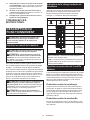
EN Cordless Angle Grinder INSTRUCTION MANUAL 9
FR Meuleuse d’Angle sans Fil MANUEL D’INSTRUCTIONS 25
DE Akku-Winkelschleifer BETRIEBSANLEITUNG 44
IT Smerigliatrice angolare a
batteria ISTRUZIONI PER L’USO 63
NL Haakse accuslijpmachine GEBRUIKSAANWIJZING 82
ES Esmeriladora Angular
Inalámbrica
MANUAL DE
INSTRUCCIONES 101
PT Esmerilhadeira Angular a
Bateria MANUAL DE INSTRUÇÕES 120
DA Ledningsfri vinkelsliber BRUGSANVISNING 138
EL
155
TR KULLANMA KILAVUZU 174

2
2
3
1
1
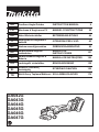
Fig.1
1
2
Fig.2
1 2
Fig.3
1
Fig.4
Fig.5
3
2
1
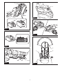
Fig.6

3
2
B
1
A
B
Fig.7
2
1
A
C
C
Fig.8
1
2
Fig.9
1
2
Fig.10
Fig.11
1
Fig.12

4
1
2
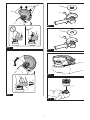
Fig.13
1
2
A
B
Fig.14
2
4
3
1
Fig.15
1
2
Fig.16
1
A
B
Fig.17
Fig.18
1
2
Fig.19

5
15°
Fig.20
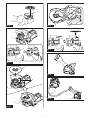
Fig.21
Fig.22
Fig.23
Fig.24
Fig.25
1
Fig.26
1
4
2
3
Fig.27

6
23
1
Fig.28
1
Fig.29
1
1
2
2
Fig.30
Fig.31
1
Fig.32

7
1
2
Fig.33
1
Fig.34
1
Fig.35
1
1
2
2
Fig.36
1
2
Fig.37
1
Fig.38

8
2
6
7
4
5
5
2
2
8
10
9
3
1
Fig.39

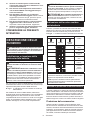
9ENGLISH
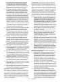
ENGLISH (Original instructions)
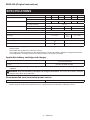
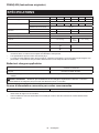
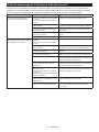
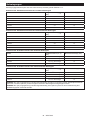
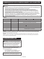
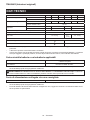
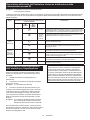
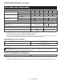
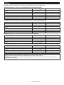
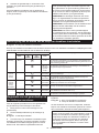
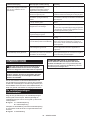
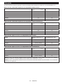
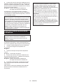
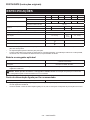
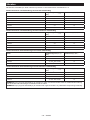
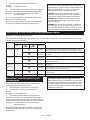
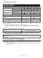
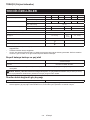
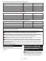
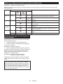
SPECIFICATIONS
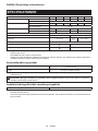
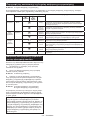
Model: GA042G GA043G GA044G GA045G GA046G GA047G
Applicable grinding wheel Max. wheel diameter 100 mm 115 mm 125 mm 100 mm 115 mm 125 mm
Max. wheel thickness 6 mm
Max. wheel diameter 100 mm 115 mm 125 mm 100 mm 115 mm 125 mm
Max. wheel thickness 1.6 mm
Applicable wire wheel brush Max. wheel diameter -115 mm -115 mm
Max. wheel thickness -16 mm -16 mm
No load speed (n0) / Rated speed (n) 8,500 min-1
Overall length (with BL4040) 433 mm 418 mm
Net weight 3.0 - 5.4 kg 2.9 -
5.3 kg
3.0 - 5.3 kg
Rated voltage D.C. 36 V - 40 V max
Speed adjusting dial -
Wireless activation function -
without notice.
-
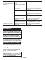
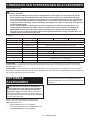
est combinations, according to EPTA-Procedure 01/2014, are shown in the table.
Applicable battery cartridge and charger
BL4020 / BL4025* / BL4040* / BL4050F* / BL4080F
Charger DC40RA / DC40RB / DC40RC
residence.
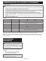
WARNING: Only use the battery cartridges and chargers listed above.
Recommended cord connected power source
Portable power pack PDC01 / PDC1200

10 ENGLISH
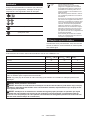
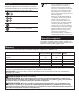
Symbols
meaning before use.
Read instruction manual.
operations.
Ni-MH
Li-ion
Due to the presence of hazardous com-
ponents in the equipment, waste electrical
and electronic equipment, accumulators
on the environment and human health.
Do not dispose of electrical and electronic
appliances or batteries with household
waste!
In accordance with the European Directive
on waste electrical and electronic equipment
and on accumulators and batteries and
waste accumulators and batteries, as well as
their adaptation to national law, waste elec-
trical equipment, batteries and accumulators
to a separate collection point for municipal
waste, operating in accordance with the
regulations on environmental protection.
crossed-out wheeled bin placed on the
equipment.
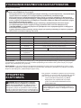
Intended use
The tool is intended for grinding, sanding, wire brushing and
cutting of metal and stone materials without the use of water.
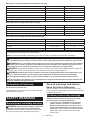
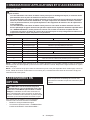
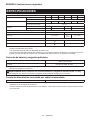
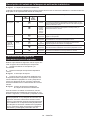
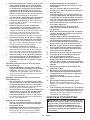
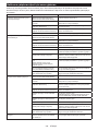
Noise
Model Sound pressure
level (LpA) : (dB(A))
Sound power level
(LWA) : (dB(A))
Uncertainty (K) :
(dB(A))
GA042G 84 92 3
GA043G 84 92 3
GA044G 84 92 3
GA045G 84 92 3
GA046G 84 92 3
GA047G 84 92 3
NOTE: The declared noise emission value(s) has been measured in accordance with a standard test method and
NOTE:
WARNING: Wear ear protection.
WARNING: -
ue(s) depending on the ways in which the tool is used especially what kind of workpiece is processed.
WARNING: Be sure to identify safety measures to protect the operator that are based on an estimation
of exposure in the actual conditions of use (taking account of all parts of the operating cycle such as the
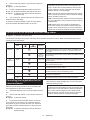
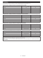
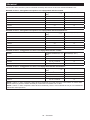
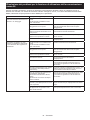
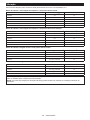
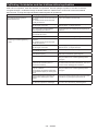
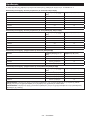
Vibration
The vibration total value (tri-axial vector sum) determined according to EN62841-2-3:
Work mode: surface grinding with normal side grip
Model
Vibration emission (ah, AG) : (m/s2)
Uncertainty (K) : (m/s2)
GA042G 3.3 1.5
GA043G 3.7 1.5
GA044G 4.5 1.5
GA045G 3.3 1.5
GA046G 3.7 1.5
GA047G 4.5 1.5

11 ENGLISH
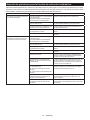
Work mode: surface grinding with anti vibration side grip
Model
Vibration emission (ah, AG) : (m/s2)
Uncertainty (K) : (m/s2)
GA042G 3.6 1.5
GA043G 4.0 1.5
GA044G 5.0 1.5
GA045G 3.6 1.5
GA046G 4.0 1.5
GA047G 5.0 1.5
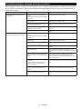
Work mode: disc sanding with normal side grip
Model
Vibration emission (ah, AG) : (m/s2)
Uncertainty (K) : (m/s2)
GA043G 2.5 m/s2 or less 1.9
GA044G 2.5 m/s2 or less 1.9
GA046G 2.5 m/s2 or less 1.9
GA047G 2.5 m/s2 or less 1.9
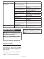
Work mode: disc sanding with anti vibration side grip
Model
Vibration emission (ah, AG) : (m/s2)
Uncertainty (K) : (m/s2)
GA043G 2.5 m/s2 or less 1.5
GA044G 2.5 m/s2 or less 1.5
GA046G 2.5 m/s2 or less 1.5
GA047G 2.5 m/s2 or less 1.5
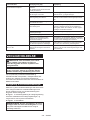
NOTE: The declared vibration total value(s) has been measured in accordance with a standard test method and
NOTE:
WARNING:
value(s) depending on the ways in which the tool is used especially what kind of workpiece is processed.
WARNING: Be sure to identify safety measures to protect the operator that are based on an estimation
of exposure in the actual conditions of use (taking account of all parts of the operating cycle such as the
WARNING: The declared vibration emission value is used for main applications of the power tool. However if
WARNING: Grinding thin sheets of metal or other easily vibrating structures with a large surface can
result in a total noise emission much higher (up to 15 dB) than the declared noise emission values.
Take the increased noise emission into consideration for both the risk assessment of noise exposure and
selecting adequate hearing protection.
Declarations of Conformity
For European countries only
to this instruction manual.
SAFETY WARNINGS
General power tool safety warnings
WARNING
Read all safety warnings, instructions,
power tool. Failure to follow all instructions listed below
Save all warnings and instruc-
tions for future reference.
(cordless) power tool.
Cordless grinder safety warnings
Safety warnings common for grinding, sanding,
1. This power tool is intended to function as a
Read all safety warnings, instructions, illus-
power tool. Failure to follow all instructions listed

12 ENGLISH
2.
Operations such as polishing or hole cutting
are not to be performed with this power tool.
Operations for which the power tool was not designed
3. Do not convert this power tool to operate in
Such a con-
4.
power tool, it does not assure safe operation.
5. The rated speed of the accessory must be at
least equal to the maximum speed marked on
the power tool. Accessories running faster than
6. The outside diameter and the thickness of your
accessory must be within the capacity rating
of your power tool.
7.
The dimensions of the accessory mounting must
power tool. Accessories that do not match the mount-
ing hardware of the power tool will run out of balance,
8. Do not use a damaged accessory. Before each
use inspect the accessory such as abrasive
wheels for chips and cracks, backing pad for
cracks, tear or excess wear, wire brush for
loose or cracked wires. If power tool or acces-
sory is dropped, inspect for damage or install
an undamaged accessory. After inspecting and
installing an accessory, position yourself and
bystanders away from the plane of the rotating
accessory and run the power tool at maximum
no-load speed for one minute. Damaged acces-
time.
9. Wear personal protective equipment.
Depending on application, use face shield,
safety goggles or safety glasses. As appro-
priate, wear dust mask, hearing protectors,
gloves and workshop apron capable of stop-
ping small abrasive or workpiece fragments.
The dust mask or respirator must be capable
10.
Keep bystanders a safe distance away from work
area. Anyone entering the work area must wear
personal protective equipment. Fragments of
11. Hold the power tool by insulated gripping
surfaces only, when performing an operation
where the cutting tool may contact hidden
wiring. Contact with a "live" wire will also make
exposed metal parts of the power tool "live" and
could give the operator an electric shock.
12. Never lay the power tool down until the acces-
sory has come to a complete stop. The spinning
13. Do not run the power tool while carrying it at
your side. Accidental contact with the spinning
14. Regularly clean the power tool’s air vents. The
motor’s fan will draw the dust inside the housing
and excessive accumulation of powdered metal
15.
materials. Sparks could ignite these materials.
16. Do not use accessories that require liquid
coolants. Using water or other liquid coolants
Kickback and related warnings:
Kickback is a sudden reaction to a pinched or snagged
-
-
trolled power tool to be forced in the direction opposite
For example, if an abrasive wheel is snagged or
entering into the pinch point can dig into the surface of
the material causing the wheel to climb out or kick out.
operator, depending on direction of the wheel’s move-
break under these conditions.
Kickback is the result of power tool misuse and/or
incorrect operating procedures or conditions and can be
1.
power tool and position your body and arms
to allow you to resist kickback forces. Always
use auxiliary handle, if provided, for maximum
control over kickback or torque reaction during
start-up. The operator can control torque reactions
or kickback forces, if proper precautions are taken.
2. Never place your hand near the rotating acces-
sory.
3. Do not position your body in the area where
power tool will move if kickback occurs.
Kickback will propel the tool in direction opposite
to the wheel’s movement at the point of snagging.
4. Use special care when working corners, sharp
edges, etc. Avoid bouncing and snagging the
accessory. Corners, sharp edges or bouncing
and cause loss of control or kickback.
5.
Do not attach a saw chain woodcarving blade,
segmented diamond wheel with a peripheral gap
greater than 10 mm or toothed saw blade. Such
blades create frequent kickback and loss of control.
operations:
1.
designed for the selected wheel. Wheels for
which the power tool was not designed cannot be
2. The grinding surface of centre depressed
wheels must be mounted below the plane of
the guard lip.
projects through the plane of the guard lip cannot

13 ENGLISH
3.
The guard must be securely attached to the
power tool and positioned for maximum safety,
so the least amount of wheel is exposed towards
the operator. The guard helps to protect the opera-
tor from broken wheel fragments, accidental contact
with wheel and sparks that could ignite clothing.
4.
-
tions. For example: do not grind with the side of
for peripheral grinding, side forces applied to these
5.
correct size and shape for your selected wheel.
6. Do not use worn down wheels from larger
power tools. A wheel intended for larger power
tool is not suitable for the higher speed of a
7. When using dual purpose wheels always use
the correct guard for the application being
performed.
not provide the desired level of guarding, which
operations:
1. -
sive pressure. Do not attempt to make an
excessive depth of cut. Overstressing the wheel
or binding of the wheel in the cut and the possibil-
2. Do not position your body in line with and
behind the rotating wheel. When the wheel, at
-
3. When the wheel is binding or when interrupt-
tool and hold it motionless until the wheel
comes to a complete stop. Never attempt to
the wheel is in motion otherwise kickback may
occur. Investigate and take corrective action to
eliminate the cause of wheel binding.
4.
Do not restart the cutting operation in the work-
piece. Let the wheel reach full speed and carefully
re-enter the cut.
kickback if the power tool is restarted in the workpiece.
5. Support panels or any oversized workpiece to
minimize the risk of wheel pinching and kick-
back. Large workpieces tend to sag under their
own weight. Supports must be placed under the
workpiece near the line of cut and near the edge
of the workpiece on both sides of the wheel.
6. Use extra caution when making a “pocket cut”
into existing walls or other blind areas. The
-
trical wiring or objects that can cause kickback.
7. Do not attempt to do curved cutting.
Overstressing the wheel increases the loading and
8. Before using a segmented diamond wheel,
make sure that the diamond wheel has the
peripheral gap between segments of 10 mm or
less, only with a negative rake angle.
1. Use proper sized sanding disc paper. Follow
manufacturers recommendations, when
selecting sanding paper. Larger sanding paper
-
tearing of the disc or kickback.
operations:
1. Be aware that wire bristles are thrown by the
brush even during ordinary operation. Do not
overstress the wires by applying excessive
load to the brush.
penetrate light clothing and/or skin.
2.
brushing, do not allow any interference of the
wire wheel or brush with the guard. Wire wheel
and centrifugal forces.
Additional Safety Warnings:
1. When using depressed centre grinding wheels,
wheels.
2. NEVER USE Stone Cup type wheels with this
grinder. This grinder is not designed for these
3. Be careful not to damage the X-LOCK holder.
Damage to the parts could result in wheel
breakage.
4. Make sure the wheel is not contacting the
workpiece before the switch is turned on.
5. Before using the tool on an actual workpiece,
let it run for a while. Watch for vibration or
wobbling that could indicate poor installation
or a poorly balanced wheel.
6. -
form the grinding.
7. Do not leave the tool running. Operate the tool
only when hand-held.
8. Do not touch the workpiece immediately after
operation; it may be extremely hot and could
burn your skin.
9. Do not touch accessories immediately after
operation; it may be extremely hot and could
burn your skin.
10. Observe the instructions of the manufacturer
for correct mounting and use of wheels.
Handle and store wheels with care.
11. Do not use separate reducing bushings or
adaptors to adapt large hole abrasive wheels.
12. Check that the workpiece is properly
supported.
13. Pay attention that the wheel continues to
14.
If working place is extremely hot and humid, or
badly polluted by conductive dust, use a short-cir-
cuit breaker (30 mA) to assure operator safety.

14 ENGLISH
15. Do not use the tool on any materials contain-
ing asbestos.
16.
the dust collecting wheel guard if required by
domestic regulation.
17. Cutting discs must not be subjected to any
lateral pressure.
18. Do not use cloth work gloves during operation.
causes tool breakage.
19.
Before operation, make sure that there is no
buried object such as electric pipe, water pipe or
gas pipe in the workpiece.
an electric shock, electrical leakage or gas leak.
SAVE THESE INSTRUCTIONS.
WARNING: DO NOT let comfort or familiarity
with product (gained from repeated use) replace
strict adherence to safety rules for the subject
product. MISUSE or failure to follow the safety
rules stated in this instruction manual may cause
serious personal injury.
Important safety instructions for
battery cartridge
1. Before using battery cartridge, read all instruc-
tions and cautionary markings on (1) battery
charger, (2) battery, and (3) product using
battery.
2. Do not disassemble or tamper with the battery
cartridge.
or explosion.
3. If operating time has become excessively
shorter, stop operating immediately. It may
result in a risk of overheating, possible burns
and even an explosion.
4. If electrolyte gets into your eyes, rinse them
out with clear water and seek medical atten-
tion right away. It may result in loss of your
eyesight.
5. Do not short the battery cartridge:
(1) Do not touch the terminals with any con-
ductive material.
(2) Avoid storing battery cartridge in a con-
tainer with other metal objects such as
nails, coins, etc.
(3) Do not expose battery cartridge to water
or rain.
A battery short can cause a large current
breakdown.
6. Do not store and use the tool and battery car-
tridge in locations where the temperature may
reach or exceed 50 °C (122 °F).
7. Do not incinerate the battery cartridge even if
it is severely damaged or is completely worn
8. Do not nail, cut, crush, throw, drop the battery
cartridge, or hit against a hard object to the
battery cartridge.
9. Do not use a damaged battery.
10.
The contained lithium-ion batteries are subject to
the Dangerous Goods Legislation requirements.
forwarding agents, special requirement on pack-
aging and labeling must be observed.
For preparation of the item being shipped, consult-
ing an expert for hazardous material is required.
national regulations.
around in the packaging.
11. When disposing the battery cartridge, remove
it from the tool and dispose of it in a safe
place. Follow your local regulations relating to
disposal of battery.
12. Use the batteries only with the products
Installing the batteries to
-
13. If the tool is not used for a long period of time,
the battery must be removed from the tool.
14. During and after use, the battery cartridge may
take on heat which can cause burns or low
temperature burns. Pay attention to the han-
dling of hot battery cartridges.
15. Do not touch the terminal of the tool imme-
diately after use as it may get hot enough to
cause burns.
16. Do not allow chips, dust, or soil stuck into the
terminals, holes, and grooves of the battery
cartridge.
-
17. Unless the tool supports the use near
high-voltage electrical power lines, do not use
the battery cartridge near high-voltage electri-
cal power lines.
18. Keep the battery away from children.
SAVE THESE INSTRUCTIONS.
CAUTION: Only use genuine Makita batteries.
Use of non-genuine Makita batteries, or batteries that
charger.
Tips for maintaining maximum
battery life
1. Charge the battery cartridge before completely
discharged. Always stop tool operation and
charge the battery cartridge when you notice
less tool power.
2. Never recharge a fully charged battery car-
tridge. Overcharging shortens the battery
service life.
3. Charge the battery cartridge with room tem-
perature at 10 °C - 40 °C (50 °F - 104 °F). Let
a hot battery cartridge cool down before
charging it.
4. When not using the battery cartridge, remove
it from the tool or the charger.

15 ENGLISH
5. Charge the battery cartridge if you do not use
it for a long period (more than six months).
Important safety instructions for
wireless unit
1. Do not disassemble or tamper with the wire-
less unit.
2. Keep the wireless unit away from young chil-
dren. If accidentally swallowed, seek medical
attention immediately.
3. Use the wireless unit only with Makita tools.
4. Do not expose the wireless unit to rain or wet
conditions.
5. Do not use the wireless unit in places where
the temperature exceeds 50 °C (122 °F).
6. Do not operate the wireless unit in places
where medical instruments, such as heart
pace makers are nearby.
7.
Do not operate the wireless unit in places where
automated devices are nearby. If operated, auto-
8. Do not operate the wireless unit in places
under high temperature or places where
static electricity or electrical noise could be
generated.
9.
The wireless unit can produce electromagnetic
10. The wireless unit is an accurate instrument. Be
careful not to drop or strike the wireless unit.
11. Avoid touching the terminal of the wireless
unit with bare hands or metallic materials.
12. Always remove the battery on the product
when installing the wireless unit into it.
13. When opening the lid of the slot, avoid the
place where dust and water may come into the
slot. Always keep the inlet of the slot clean.
14. Always insert the wireless unit in the correct
direction.
15. Do not press the wireless activation button
on the wireless unit too hard and/or press the
button with an object with a sharp edge.
16.
Always close the lid of the slot when operating.
17.
Do not remove the wireless unit from the slot
while the power is being supplied to the tool.
18. Do not remove the sticker on the wireless unit.
19. Do not put any sticker on the wireless unit.
20. Do not leave the wireless unit in a place where
static electricity or electrical noise could be
generated.
21. Do not leave the wireless unit in a place sub-
ject to high heat, such as a car sitting in the
sun.
22. Do not leave the wireless unit in a dusty or
powdery place or in a place corrosive gas
could be generated.
23. Sudden change of the temperature may bedew
the wireless unit. Do not use the wireless unit
until the dew is completely dried.
24. When cleaning the wireless unit, gently wipe
with a dry soft cloth. Do not use benzine, thin-
ner, conductive grease or the like.
25. When storing the wireless unit, keep it in the
supplied case or a static-free container.
26. Do not insert any devices other than Makita
wireless unit into the slot on the tool.
27. Do not use the tool with the lid of the slot dam-
aged.
cause malfunction.
28. Do not pull and/or twist the lid of the slot more
than necessary.
from the tool.
29. Replace the lid of the slot if it is lost or
damaged.
SAVE THESE INSTRUCTIONS.
FUNCTIONAL
DESCRIPTION
CAUTION: Always be sure that the tool is
before adjusting or checking function on the tool.
Installing or removing battery
cartridge
CAUTION:
installing or removing of the battery cartridge.
CAUTION: Hold the tool and the battery car-
cartridge.
while sliding the button on the front of the cartridge.
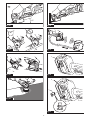
Fig.1: 1. Red indicator 2. Button 3.
CAUTION: Always install the battery cartridge
fully until the red indicator cannot be seen. If not,
CAUTION: Do not install the battery cartridge
forcibly.

16 ENGLISH
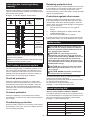
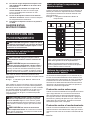
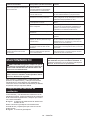
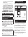
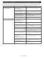
Indicating the remaining battery
capacity
-
light up for a few seconds.
Fig.2: 1. Indicator lamps 2. Check button
Indicator lamps Remaining
capacity
Lighted Blinking
75% to 100%
50% to 75%
25% to 50%
0% to 25%
Charge the
malfunctioned.
NOTE: Depending on the conditions of use and the
NOTE:
Tool / battery protection system
-
-
placed under one of the following conditions:
Overload protection
-
caused the tool to become overloaded. Then turn the
tool on to restart.
Overheat protection
tool on again.
Overdischarge protection
Releasing protection lock
In this situation, the tool does not start even if turning
Protections against other causes
that could damage the tool and allows the tool to stop
halt or stop in operation.
restart.
Switch action
CAUTION: Before installing the battery car-
tridge into the tool, always check to see that the
switch lever actuates properly and returns to the
"OFF" position when released.
CAUTION: For your safety, this tool is
tool from unintended starting. NEVER use the tool
if it runs when you simply pull the switch lever
to our authorized service center for proper repairs
BEFORE further usage.
CAUTION: Do not pull the switch lever hard
This can cause
switch breakage.
CAUTION: NEVER tape down or defeat pur-
-
tor and then pull the switch lever.
To stop the tool, release the switch lever.
Fig.3: 1.2. Switch lever
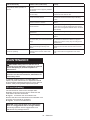
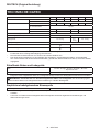
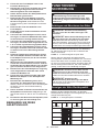
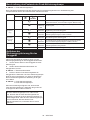
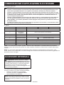
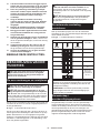
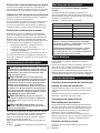
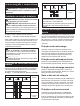
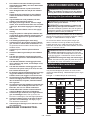
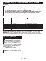
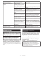
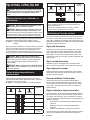
Speed adjusting dial
Only for model GA042G / GA043G / GA044G
the speed adjusting dial. The table below shows the num-
ber on the dial and the corresponding rotation speed.
Fig.4: 1. Speed adjusting dial
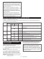
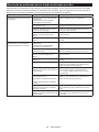
Number Speed
13,000 min-1
24,500 min-1
36,000 min-1
47,500 min-1
58,500 min-1

17 ENGLISH
NOTICE: If the tool is operated continuously at
low speed for a long time, the motor will get over-
loaded, resulting in tool malfunction.
NOTICE: The speed adjusting dial can be turned
only as far as 5 and back to 1. Do not force it past
5 or 1, or the speed adjusting function may no
longer work.
Electric brake
the switch still on.
Center.
Electronic function
Accidental re-start preventive
function
ON, the tool does not start.
Active Feedback sensing Technology
further rotation of the spindle (it does not prevent
kickback).
cause of sudden drop in the rotation speed, and then
turn the tool on.
Soft start feature
Soft start feature reduces starting reaction.
ASSEMBLY
CAUTION: Always be sure that the tool is
before adjusting or checking function on the tool.
Installing side grip (handle)
CAUTION: Always be sure that the side grip is
installed securely before operation.
Fig.5
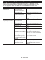
Installing or removing wheel guard
WARNING: When using a depressed center
closed side of the guard always points toward the
operator.
WARNING: Make sure that the wheel guard is
securely locked by the lock lever with one of the
holes on the wheel guard.
WARNING:
/ diamond wheel, be sure to use only the special
disc, wire wheel brush / abrasive cut-
1. While pushing the lock lever, mount the wheel
guard with the protrusions on the wheel guard aligned
with the notches on the bearing box.
Fig.6: 1. Lock lever 2. Notch 3. Protrusion
2.
While pushing the lock lever toward A, hold down
Fig.7: 1. Wheel guard 2. Hole
NOTE: Push down the wheel guard straight.
3.
While pushing the lock lever toward A, rotate the wheel
guard toward C, and then, change the angle of the wheel
guard according to the work so that the operator can be pro-
tected. Align the lock lever with one of the holes in the wheel
guard, and then release the lock lever to lock the wheel guard.
Fig.8: 1. Wheel guard 2. Hole
To remove wheel guard, follow the installation proce-
dure in reverse.
Installing depressed center wheel or
Optional accessory
WARNING: When using a depressed center
guard always points toward the operator.
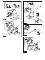
Fig.9: 1. Depressed center wheel 2. Wheel guard
wheel
Optional accessory
WARNING:
/ diamond wheel, be sure to use only the special
WARNING:
grinding.
Fig.10: 1.
2.
diamond wheel

18 ENGLISH
Clip-on cutting wheel guard attachment
Optional accessory
NOTE:
wheel guard attachment can be used with the wheel
guard (for grinding wheel).
Not available in some countries.
Fig.11
Installing wire cup brush
Optional accessory
CAUTION: Do not use wire cup brush that is
damaged, or which is out of balance. Use of dam-
contact with broken brush wires.
Fig.12: 1. Wire cup brush
Installing wire wheel brush
Optional accessory
CAUTION: Do not use wire wheel brush that
is damaged, or which is out of balance. Use of
damaged wire wheel brush could increase potential
CAUTION: ALWAYS use guard with wire
inside guard. Wheel can shatter during use and
Fig.13: 1. Wire wheel brush 2. Wheel guard
Installing or removing X-LOCK
wheel
WARNING: Never actuate the release lever of
the X-LOCK holder during operation. Make sure
that the X-LOCK wheel has stopped completely
when removing it. Otherwise, the X-LOCK wheel
CAUTION: Use only original X-LOCK wheels
with the X-LOCK logo. This tool is dedicated to
X-LOCK.
guaranteed with original X-LOCK wheels.
-
ing, and cause the clamp tool to come loose.
CAUTION: Do not touch the X-LOCK wheel
immediately after operation.
CAUTION: Make sure that the X-LOCK wheel
and holder of the tool are not deformed and are
free from dust or foreign matters.
CAUTION:
holder while installing or removing the X-LOCK
wheel.
CAUTION:
release lever while installing the X-LOCK wheel. It
NOTE:
or lock nuts are required to install or remove the
X-LOCK wheels.
1. To install the X-LOCK wheel, make sure that both
catches are in the unlocked position.
If not, push the release lever from A side to lift B
side, then pull the release lever from B side as illus-
trated. The catches are set in the unlocked position.
Fig.14: 1. Catch 2. Release lever
2. Place a central position of the X-LOCK wheel on
the holder.
Make sure the X-LOCK wheel is parallel to the
3. Push the X-LOCK wheel into the holder. The
catches snap into the lock position with a click and
Fig.15: 1. X-LOCK wheel 2. Holder 3. Flange sur-
face 4. Catch
The surface of the X-LOCK wheel is no higher
than the surface of the holder as shown in the
If not, the holder must be cleaned or the X-LOCK
wheel must not be used.
Fig.16: 1. Surface of the holder 2. Surface of the
X-LOCK wheel
To remove the X-LOCK wheel, push the release lever
from A side to lift B side, then pull the release lever from
B side as illustrated.
The X-LOCK wheel is released and can be removed.
Fig.17: 1. Release lever
Installing dust collecting wheel
Optional accessory
cutting stone materials.
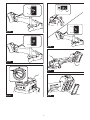
Fig.18
NOTE: For information how to install the dust col-
lecting wheel guard, refer to the manual of the dust
collecting wheel guard.
Connecting a vacuum cleaner
Optional accessory
WARNING: Never vacuum metal particles
created by grinding/cutting/sanding operation.
cleaner.
-
ting, use a dust collecting wheel guard and a vacuum
cleaner.
Refer to the instruction manual attached to the dust
collecting wheel guard for assembling and using it.
Fig.19: 1. Dust collecting wheel guard 2. Hose of
the vacuum cleaner

19 ENGLISH
OPERATION
WARNING: It should never be necessary to
force the tool. The weight of the tool applies ade-
quate pressure. Forcing and excessive pressure
could cause dangerous wheel breakage.
WARNING: ALWAYS replace wheel if tool is
dropped while grinding.
WARNING: NEVER hit the workpiece with the
wheel.
WARNING: Avoid bouncing and snagging
the wheel, especially when working corners,
sharp edges etc. This can cause loss of control and
kickback.
WARNING: NEVER use tool with wood cutting
blades and other saw blades. Such blades when
WARNING: Never actuate the release lever of
the X-LOCK holder during operation. The X-LOCK
WARNING: Make sure that the X-LOCK wheel
CAUTION: Never switch on the tool when it
is in contact with the workpiece, it may cause an
injury to operator.
CAUTION: Always wear safety goggles or a
face shield during operation.
CAUTION:
the tool and wait until the wheel has come to a
complete stop before putting the tool down.
CAUTION:
one hand on housing and the other on the side
grip (handle).
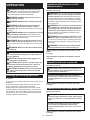
Grinding and sanding operation
Fig.20
workpiece.
In general, keep the edge of the wheel or disc at an
angle of about 15° to the workpiece surface.
During the break-in period with a new wheel, do not
the workpiece. Once the edge of the wheel has been
forward and backward direction.
diamond wheel
Optional accessory
WARNING: Do not "jam" the wheel or apply
excessive pressure. Do not attempt to make an
excessive depth of cut. Overstressing the wheel
of kickback, wheel breakage and overheating of the
WARNING: Do not start the cutting operation
in the workpiece. Let the wheel reach full speed
and carefully enter into the cut moving the tool
forward over the workpiece surface. The wheel
started in the workpiece.
WARNING: During cutting operations, never
change the angle of the wheel. Placing side pres-
the wheel to crack and break, causing serious per-
WARNING: A diamond wheel shall be oper-
ated perpendicular to the material being cut.
wheel
Fig.21
Usage example: operation with diamond wheel
Fig.22
Operation with wire cup brush
Optional accessory
CAUTION: Check operation of brush by run-
ning tool with no load, insuring that no one is in
front of or in line with brush.
NOTICE: Avoid applying too much pressure
which causes over bending of wires when using
the wire cup brush.
breakage.
Usage example: operation with wire cup brush
Fig.23
Operation with wire wheel brush
Optional accessory
CAUTION: Check operation of wire wheel
brush by running tool with no load, insuring that
no one is in front of or in line with the wire wheel
brush.
NOTICE: Avoid applying too much pressure
which causes over bending of wires when
using wire wheel brush.
breakage.
Usage example: operation with wire wheel brush
Fig.24

20 ENGLISH
WIRELESS ACTIVATION
FUNCTION
Only for model GA042G / GA043G / GA044G
What you can do with the wireless
activation function
The wireless activation function enables clean and com-
Fig.25
To use the wireless activation function, prepare follow-
ing items:
• A vacuum cleaner which supports the wireless
activation function
The overview of the wireless activation function
setting is as follows. Refer to each section for detail
procedures.
1. Installing the wireless unit
2. Tool registration for the vacuum cleaner
3. Starting the wireless activation function
Installing the wireless unit
Optional accessory
CAUTION:
surface when installing the wireless unit.
NOTICE: Clean the dust and dirt on the tool
before installing the wireless unit. Dust or dirt
wireless unit.
NOTICE: To prevent the malfunction caused by
static, touch a static discharging material, such
as a metal part of the tool, before picking up the
wireless unit.
NOTICE: When installing the wireless unit,
always be sure that the wireless unit is inserted
in the correct direction and the lid is completely
closed.
1.
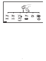
Fig.26: 1. Lid
2. Insert the wireless unit to the slot and then close
the lid.
When inserting the wireless unit, align the projections
with the recessed portions on the slot.
Fig.27: 1. Wireless unit 2. Projection 3. Lid
4. Recessed portion
The hooks on the back of the lid will lift the wireless unit
Fig.28: 1. Wireless unit 2. Hook 3. Lid
After removing the wireless unit, keep it in the supplied
case or a static-free container.
NOTICE: Always use the hooks on the back of
the lid when removing the wireless unit. If the
hooks do not catch the wireless unit, close the lid
Tool registration for the vacuum
cleaner
NOTE: A Makita vacuum cleaner supporting the
wireless activation function is required for the tool
registration.
NOTE: Finish installing the wireless unit to the tool
before starting the tool registration.
NOTE: During the tool registration, do not pull the
switch trigger or turn on the power switch on the
vacuum cleaner.
NOTE: Refer to the instruction manual of the vacuum
cleaner, too.
-
tion beforehand.
1. Install the batteries to the vacuum cleaner and the
tool.
2.
"AUTO".
Fig.29: 1.
3. Press the wireless activation button on the vac-
uum cleaner for 3 seconds until the wireless activation
lamp blinks in green. And then press the wireless acti-
Fig.30: 1. Wireless activation button 2. Wireless
activation lamp
If the vacuum cleaner and the tool are linked success-
for 2 seconds and start blinking in blue.
NOTE:
in green after 20 seconds elapsed. Press the wireless
activation button on the tool while the wireless acti-
vation lamp on the cleaner is blinking. If the wireless
activation lamp does not blink in green, push the wire-
NOTE: When performing two or more tool registra-
-
Starting the wireless activation
function
NOTE: Finish the tool registration for the vacuum
cleaner prior to the wireless activation.
NOTE: Refer to the instruction manual of the vacuum
cleaner, too.
After registering a tool to the vacuum cleaner, the
switch operation of the tool.
1. Install the wireless unit to the tool.
2. Connect the hose of the vacuum cleaner with the
tool.
Fig.31
Sayfa yükleniyor...
Sayfa yükleniyor...
Sayfa yükleniyor...
Sayfa yükleniyor...
Sayfa yükleniyor...
Sayfa yükleniyor...
Sayfa yükleniyor...
Sayfa yükleniyor...
Sayfa yükleniyor...
Sayfa yükleniyor...
Sayfa yükleniyor...
Sayfa yükleniyor...
Sayfa yükleniyor...
Sayfa yükleniyor...
Sayfa yükleniyor...
Sayfa yükleniyor...
Sayfa yükleniyor...
Sayfa yükleniyor...
Sayfa yükleniyor...
Sayfa yükleniyor...
Sayfa yükleniyor...
Sayfa yükleniyor...
Sayfa yükleniyor...
Sayfa yükleniyor...
Sayfa yükleniyor...
Sayfa yükleniyor...
Sayfa yükleniyor...
Sayfa yükleniyor...
Sayfa yükleniyor...
Sayfa yükleniyor...
Sayfa yükleniyor...
Sayfa yükleniyor...
Sayfa yükleniyor...
Sayfa yükleniyor...
Sayfa yükleniyor...
Sayfa yükleniyor...
Sayfa yükleniyor...
Sayfa yükleniyor...
Sayfa yükleniyor...
Sayfa yükleniyor...
Sayfa yükleniyor...
Sayfa yükleniyor...
Sayfa yükleniyor...
Sayfa yükleniyor...
Sayfa yükleniyor...
Sayfa yükleniyor...
Sayfa yükleniyor...
Sayfa yükleniyor...
Sayfa yükleniyor...
Sayfa yükleniyor...
Sayfa yükleniyor...
Sayfa yükleniyor...
Sayfa yükleniyor...
Sayfa yükleniyor...
Sayfa yükleniyor...
Sayfa yükleniyor...
Sayfa yükleniyor...
Sayfa yükleniyor...
Sayfa yükleniyor...
Sayfa yükleniyor...
Sayfa yükleniyor...
Sayfa yükleniyor...
Sayfa yükleniyor...
Sayfa yükleniyor...
Sayfa yükleniyor...
Sayfa yükleniyor...
Sayfa yükleniyor...
Sayfa yükleniyor...
Sayfa yükleniyor...
Sayfa yükleniyor...
Sayfa yükleniyor...
Sayfa yükleniyor...
Sayfa yükleniyor...
Sayfa yükleniyor...
Sayfa yükleniyor...
Sayfa yükleniyor...
Sayfa yükleniyor...
Sayfa yükleniyor...
Sayfa yükleniyor...
Sayfa yükleniyor...
Sayfa yükleniyor...
Sayfa yükleniyor...
Sayfa yükleniyor...
Sayfa yükleniyor...
Sayfa yükleniyor...
Sayfa yükleniyor...
Sayfa yükleniyor...
Sayfa yükleniyor...
Sayfa yükleniyor...
Sayfa yükleniyor...
Sayfa yükleniyor...
Sayfa yükleniyor...
Sayfa yükleniyor...
Sayfa yükleniyor...
Sayfa yükleniyor...
Sayfa yükleniyor...
Sayfa yükleniyor...
Sayfa yükleniyor...
Sayfa yükleniyor...
Sayfa yükleniyor...
Sayfa yükleniyor...
Sayfa yükleniyor...
Sayfa yükleniyor...
Sayfa yükleniyor...
Sayfa yükleniyor...
Sayfa yükleniyor...
Sayfa yükleniyor...
Sayfa yükleniyor...
Sayfa yükleniyor...
Sayfa yükleniyor...
Sayfa yükleniyor...
Sayfa yükleniyor...
Sayfa yükleniyor...
Sayfa yükleniyor...
Sayfa yükleniyor...
Sayfa yükleniyor...
Sayfa yükleniyor...
Sayfa yükleniyor...
Sayfa yükleniyor...
Sayfa yükleniyor...
Sayfa yükleniyor...
Sayfa yükleniyor...
Sayfa yükleniyor...
Sayfa yükleniyor...
Sayfa yükleniyor...
Sayfa yükleniyor...
Sayfa yükleniyor...
Sayfa yükleniyor...
Sayfa yükleniyor...
Sayfa yükleniyor...
Sayfa yükleniyor...
Sayfa yükleniyor...
Sayfa yükleniyor...
Sayfa yükleniyor...
Sayfa yükleniyor...
Sayfa yükleniyor...
Sayfa yükleniyor...
Sayfa yükleniyor...
Sayfa yükleniyor...
Sayfa yükleniyor...
Sayfa yükleniyor...
Sayfa yükleniyor...
Sayfa yükleniyor...
Sayfa yükleniyor...
Sayfa yükleniyor...
Sayfa yükleniyor...
Sayfa yükleniyor...
Sayfa yükleniyor...
Sayfa yükleniyor...
Sayfa yükleniyor...
Sayfa yükleniyor...
Sayfa yükleniyor...
Sayfa yükleniyor...
Sayfa yükleniyor...
Sayfa yükleniyor...
Sayfa yükleniyor...
Sayfa yükleniyor...
Sayfa yükleniyor...
Sayfa yükleniyor...
Sayfa yükleniyor...
Sayfa yükleniyor...
Sayfa yükleniyor...
Sayfa yükleniyor...
Sayfa yükleniyor...
Sayfa yükleniyor...
Sayfa yükleniyor...
Sayfa yükleniyor...
Sayfa yükleniyor...
Sayfa yükleniyor...
Sayfa yükleniyor...
Sayfa yükleniyor...
Sayfa yükleniyor...
-
 1
1
-
 2
2
-
 3
3
-
 4
4
-
 5
5
-
 6
6
-
 7
7
-
 8
8
-
 9
9
-
 10
10
-
 11
11
-
 12
12
-
 13
13
-
 14
14
-
 15
15
-
 16
16
-
 17
17
-
 18
18
-
 19
19
-
 20
20
-
 21
21
-
 22
22
-
 23
23
-
 24
24
-
 25
25
-
 26
26
-
 27
27
-
 28
28
-
 29
29
-
 30
30
-
 31
31
-
 32
32
-
 33
33
-
 34
34
-
 35
35
-
 36
36
-
 37
37
-
 38
38
-
 39
39
-
 40
40
-
 41
41
-
 42
42
-
 43
43
-
 44
44
-
 45
45
-
 46
46
-
 47
47
-
 48
48
-
 49
49
-
 50
50
-
 51
51
-
 52
52
-
 53
53
-
 54
54
-
 55
55
-
 56
56
-
 57
57
-
 58
58
-
 59
59
-
 60
60
-
 61
61
-
 62
62
-
 63
63
-
 64
64
-
 65
65
-
 66
66
-
 67
67
-
 68
68
-
 69
69
-
 70
70
-
 71
71
-
 72
72
-
 73
73
-
 74
74
-
 75
75
-
 76
76
-
 77
77
-
 78
78
-
 79
79
-
 80
80
-
 81
81
-
 82
82
-
 83
83
-
 84
84
-
 85
85
-
 86
86
-
 87
87
-
 88
88
-
 89
89
-
 90
90
-
 91
91
-
 92
92
-
 93
93
-
 94
94
-
 95
95
-
 96
96
-
 97
97
-
 98
98
-
 99
99
-
 100
100
-
 101
101
-
 102
102
-
 103
103
-
 104
104
-
 105
105
-
 106
106
-
 107
107
-
 108
108
-
 109
109
-
 110
110
-
 111
111
-
 112
112
-
 113
113
-
 114
114
-
 115
115
-
 116
116
-
 117
117
-
 118
118
-
 119
119
-
 120
120
-
 121
121
-
 122
122
-
 123
123
-
 124
124
-
 125
125
-
 126
126
-
 127
127
-
 128
128
-
 129
129
-
 130
130
-
 131
131
-
 132
132
-
 133
133
-
 134
134
-
 135
135
-
 136
136
-
 137
137
-
 138
138
-
 139
139
-
 140
140
-
 141
141
-
 142
142
-
 143
143
-
 144
144
-
 145
145
-
 146
146
-
 147
147
-
 148
148
-
 149
149
-
 150
150
-
 151
151
-
 152
152
-
 153
153
-
 154
154
-
 155
155
-
 156
156
-
 157
157
-
 158
158
-
 159
159
-
 160
160
-
 161
161
-
 162
162
-
 163
163
-
 164
164
-
 165
165
-
 166
166
-
 167
167
-
 168
168
-
 169
169
-
 170
170
-
 171
171
-
 172
172
-
 173
173
-
 174
174
-
 175
175
-
 176
176
-
 177
177
-
 178
178
-
 179
179
-
 180
180
-
 181
181
-
 182
182
-
 183
183
-
 184
184
-
 185
185
-
 186
186
-
 187
187
-
 188
188
-
 189
189
-
 190
190
-
 191
191
-
 192
192


diğer dillerde
- español: Makita GA042G Manual de usuario
- français: Makita GA042G Manuel utilisateur
- italiano: Makita GA042G Manuale utente
- Deutsch: Makita GA042G Benutzerhandbuch
- português: Makita GA042G Manual do usuário
- dansk: Makita GA042G Brugermanual
- Nederlands: Makita GA042G Handleiding