HP DesignJet 8000 Printer series Yükleme Rehberi
- Kategori
- Yazdır
- Tip
- Yükleme Rehberi

tiksgnuthcirro
v
le
k
c
i
wfu
A
hcu
bd
n
a
hsno
i
ta
lla
tsn
I
e
d
rue
l
uo
r
ne'
d
t
iK
s
t
ne
m
uco
d
n
o
i
talla
t
s
n
i'd ediu
G
e
nois
n
e
t
id
o
ll
u
r
led
ti
K
e
n
o
iz
alla
tsn
i
id
ela
una
M
ad
i
g
o
ce
r ed
oll
i
dor led
t
iK
nói
c
a
l
at
s
n
i
e
d
a
íu
G
ed anib
o
b ad
ti
K
o
tn
em
i
h
l
ocer
o
ã
ç
al
ats
ni e
d
ai
uG
ςοτ
α
µγ
ί
λυΤ ύ
ο
ιλυ
ο
ραΚ τιΚ
ςησατσάτ
α
κγΕ
ς
ό
γ
ηδ
Ο
ykví
c
í
c
ejívan
adaS
icalat
s
n
i
or
p akčur
í
řP
t
elzsék
ósroől
é
v
é
s
c
v
yn
ö
k
izé
k
isé
tí
p
ele
T
jezcr
o
i
b
d
o
ilupzs watseZ
użatnom ajckurt
s
nI
йонм
еи
рп ткелпмоК
а
ретнир
п
ялд
ы
нибоб
екво
н
ат
с
у
оп о
в
тсдо
в
о
к
уР
i
te
S
ı
sara
k
aM amra
kı
Ç
u
z
uvalıK muluruK
RE
VOC
T
NORF m
m
01
2
X
m
m84
1E
N
I
PS
m
m
5
6
.
1
1
R
E
VOC
K
C
A
B
mm
0
1
2
X
m
m
8
4
1
HP Designjet 8000s Take-Up Reel Kit Installation Guide
t
iK l
e
eR pU-ekaT s0
0
08 te
j
ngiseD PH
ed
i
uG noitallatsnI
.P.L ,ynapmoC tnempoleveD drakcaP-ttelw
e
H 60
0
2
©
moc.ph.ww
w
Printed in Japan

HP Designjet 8000s Take-Up Reel Kit
Installation Guide

Legal notices
The information contained in this document
is subject to change without notice.
Hewlett-Packard makes no warranty of any
kind with regard to this material, including,
but not limited to, the implied warranties of
merchantability and fitness for a particular
purpose.
Hewlett-Packard shall not be liable for errors
contained herein or for incidental or
consequential damages in connection with
the furnishing, performance, or use of this
material.
No part of this document may be photocopied
or translated to another language without the
prior written consent of Hewlett-Packard
Company.

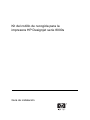
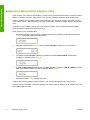
Installing the take-up reel
This Installation Guide contains information necessary to install and set up the HP Designjet 8000s Take-
up Reel Kit (Model Q6681A). For information about using the take-up reel, refer to the HP Designjet 8000s
Printer User's Guide.
Two people will be required to install the take-up reel. Make sure there is enough space to access the front
and the rear of the printer. All mechanical installation takes place from the front of the printer and electrical
connections are made at the rear.
The tool you need to install the take-up reel is included in the box, and consists of a cross-head (Phillips)
screwdriver.
To install the take-up reel:
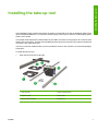
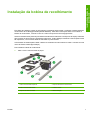
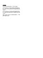
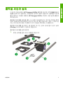
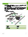
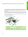
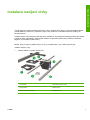
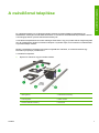
1. Open the box and remove all parts.
1. Left end plate. 4. Take-up reel assembly.
2. Right end plate. 5. Motor cable.
3. Media sensor assembly. 6. Tension bar.
ENWW 1
Installing the take-up reel

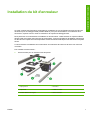
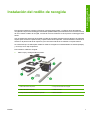
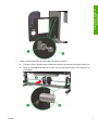
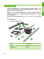
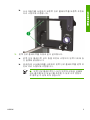
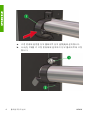
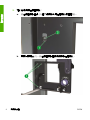
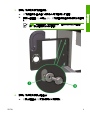
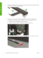
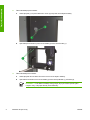
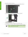
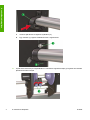
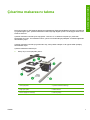
2. Install the right end plate as follows:
a. Insert the lip (1) on the right end plate into the slot (2) on the right leg on the printer stand.
b. Install three screws (1) to fix the right end plate to the right printer leg stand.
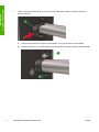
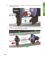
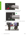
3. Install the left end plate as follows:
a. Insert the lip on the left end plate into the slot on the left leg on the printer stand.
b. Install three washers (1) and screws (2) to fix the left end plate to the left printer leg stand.
NOTE The left end plate allows for vertical movement so that the take-up reel height
can be adjusted even with the screws fully inserted.
2 Installing the take-up reel ENWW
Installing the take-up reel

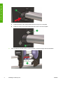
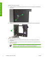
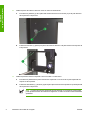
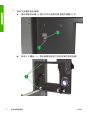
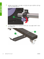
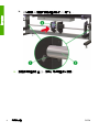
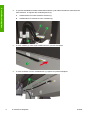
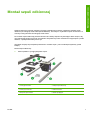
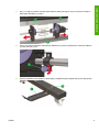
4. Install the take-up reel assembly as follows:
a. Place the take-up reel assembly (3) onto the printer stand crossbar.
b. Rest the ends of the support bar (2) on the ledges (1) on each end plate.
5. Install the holding bracket (1) at each end to secure the support bar as follows:
ENWW 3
Installing the take-up reel

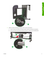
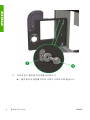
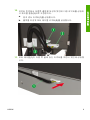
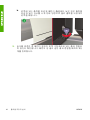
a. Install the bottom of the holding bracket into the slot (2) on the end plate.
b. Install one screw (1) into each holding bracket to secure it to the end plate.
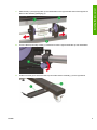
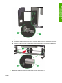
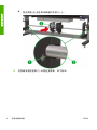
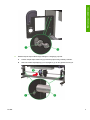
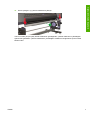
6. Turn the take-up reel stop screws (1) anti-clockwise to release the right and left assemblies.
4 Installing the take-up reel ENWW
Installing the take-up reel

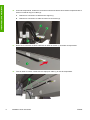
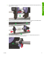
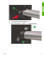
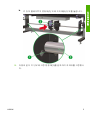
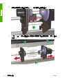
7. Slide the left (1) and right (2) take-up reel assemblies to the right and left ends of the support bar.
Remove the assembly packaging (3).
8. Turn the take-up reel stop screws (1) clockwise to lock the right and left take-up reel assemblies.
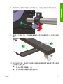
9. Install one screw (2) to secure the take-up reel media sensor assembly (1) to the right stand.
ENWW 5
Installing the take-up reel

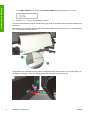
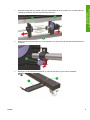
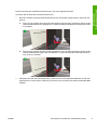
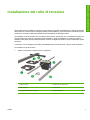
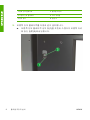
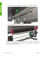
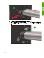
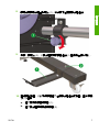
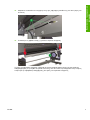
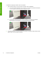
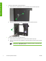
10. At the rear of the printer, insert the following connectors into the rear of the right take-up reel assembly
and secure them with the cable clip (3):
a. Insert the media sensor connector (1).
b. Insert the take-up reel motor cable connector (2).
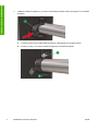
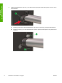
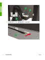
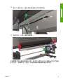
11. Insert the connector on the other end of the motor cable (1) into the rear of the printer.
12. Secure the motor cable with the three cable clips (1) on the rear of the printer.
6 Installing the take-up reel ENWW
Installing the take-up reel

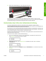
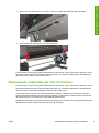
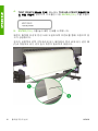
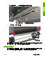
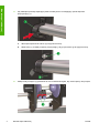
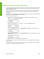
13. Load the tension bar (1) into the take-up reel.
The height of the take-up reel may require adjustment as it must be horizontally aligned to the media output
from the printer. Refer to the next section to verify alignment of the take-up reel height.
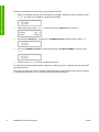
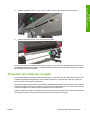
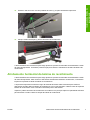
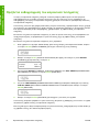
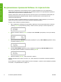
Take-up reel horizontal alignment
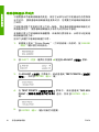
The height of the take-up reel may require adjustment as it must be horizontally aligned to the media output
from the printer. To verify alignment of the take-up reel height you need to print the take-up reel test print.
The printer will print a line across the width of the media. Use this line to check the alignment of the right
side of the take-up reel with the left side. Use the take-up reel tension bar as the horizontal reference for
alignment.
Print the take-up reel pattern on roll media to ensure that there is sufficient length to feed the media to the
tension bar on the take-up reel.
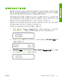
Print the take-up reel print as follows:
1. When the "Printer Ready" message appears on the Front Panel, press the ONLINE key to take the
Printer offline.
2. Press the SHIFT key twice and select the ADJUST menu using the ◄ key.
3. In the ADJUST submenu, scroll to TEST PRINTS and press the ENTER key.
ENWW Take-up reel horizontal alignment 7
Installing the take-up reel

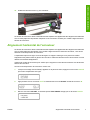
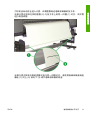
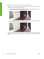
4. In the TEST PRINTS menu scroll to the TUR ADJ PRINToption and press the ENTER key.
5. Press the ENTER key to start printing the pattern.
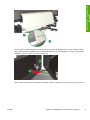
The printer automatically feeds the media through the printer so that the pattern reaches the take-up reel
tension bar.
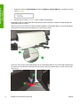
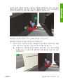
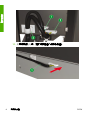
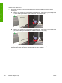
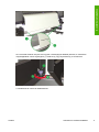
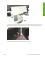
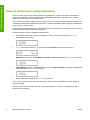
If the pattern (2) on the right and left edge of the media is aligned with the same groove (1) on the tension
bar, no height adjustment is required.
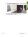
If the pattern on the left edge of the media is not aligned with the same groove as on the right edge, use
the take-up reel height screw (1) to adjust the take-up reel height up (2) or down (3).
8 Installing the take-up reel ENWW
Installing the take-up reel

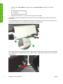
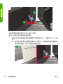
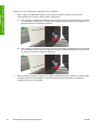
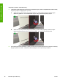
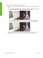
Only the left side of the take-up reel can be adjusted up or down.
Adjust the height of the take-up reel as follows:
1. If the take-up reel pattern on the left edge of the media is not aligned with the groove, do one of the
following:
a. If the take-up reel pattern on the left side is higher than the groove (1), turn the take-up reel height
screw clockwise to raise the left side of the take-up reel.
b. If the take-up reel pattern on the left side is lower than the groove (2), turn the take-up reel height
screw anti-clockwise to lower the left side of the take-up reel.
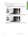
2. After adjusting the height, check that the pattern is aligned with the groove on the left edge of the
media. Repeat step two until both ends of the pattern are aligned with the same groove.
ENWW Take-up reel horizontal alignment 9
Installing the take-up reel

10 Installing the take-up reel ENWW
Installing the take-up reel

HP Designjet 8000s
Aufwickelvorrichtungskit
Installationshandbuch

Rechtliche Hinweise
Die in diesem Handbuch enthaltenen
Informationen können ohne Vorankündigung
geändert werden.
Hewlett-Packard übernimmt keinerlei
Gewährleistung bezüglich dieses Materials,
einschließlich, jedoch nicht beschränkt auf
die stillschweigende Garantie der
handelsüblichen Qualität oder Eignung für
einen bestimmten Zweck.
Hewlett-Packard haftet nicht für etwaige hier
enthaltene Fehler bzw. für Neben- oder
Folgeschäden, die in Verbindung mit der
Bereitstellung oder Verwendung dieses
Materials entstehen können.
Dieses Dokument darf ohne vorherige
schriftliche Genehmigung durch Hewlett-
Packard weder ganz noch teilweise kopiert
oder in eine andere Sprache übersetzt
werden.

Installieren der Aufwickelvorrichtung
In diesem Installationshandbuch finden Sie Anleitungen zum Zusammenbauen und Anbringen des HP
Designjet 8000s Aufwickelvorrichtungskits (Modell Q6681A) am Drucker. Informationen zur Verwendung
der Aufwickelvorrichtung finden Sie im Benutzerhandbuch für den Drucker HP Designjet 8000s.
Für das Installieren der Aufwickelvorrichtung werden zwei Personen benötigt. Achten Sie darauf, dass vor
und hinter dem Drucker genügend Platz zum Durchführen der Arbeiten frei ist. Alle mechanischen Arbeiten
werden an der Vorderseite des Druckers durchgeführt. Die elektrischen Anschlüsse werden an der
Rückseite hergestellt.
Das zum Installieren der Aufwickelvorrichtung benötigte Werkzeug, ein Kreuzschlitzschraubendreher, ist
im Lieferumfang enthalten.
So installieren Sie die Aufwickelvorrichtung:
1. Öffnen Sie die Verpackung, und nehmen Sie alle Teile heraus.
1. Linke Endplatte 4. Aufwickelvorrichtung
2. Rechte Endplatte 5. Motorkabel
3. Mediensensoreinheit 6. Spannstange
DEWW 1
Installieren der
Aufwickelvorrichtun
g

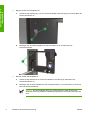
2. Bringen Sie die rechte Endplatte an:
a. Setzen Sie die Haltezunge (1) an der rechten Endplatte in die Öffnung (2) im rechten Bein des
Druckerstandfußes ein.
b. Befestigen Sie die rechte Endplatte mit drei Schrauben (1) am rechten Bein des
Druckerstandfußes.
3. Bringen Sie die linke Endplatte an:
a. Setzen Sie die Haltezunge an der linken Endplatte in die Öffnung im linken Bein des
Druckerstandfußes ein.
b. Befestigen Sie die linke Endplatte mit drei Unterlegscheiben (1) und Schrauben (2) am linken
Bein des Druckerstandfußes.
Hinweis Die linke Endplatte lässt sich vertikal bewegen, damit die Höhe der
Aufwickelvorrichtung selbst bei vollständig angezogenen Schrauben justiert werden
kann.
2 Installieren der Aufwickelvorrichtung DEWW
Installieren der
Aufwickelvorrichtun
g

4. Bringen Sie die Aufwickelvorrichtung an:
a. Platzieren Sie die Aufwickelvorrichtung (3) auf der Querverstrebung des Druckerstandfußes.
b. Setzen Sie die Enden der Laufstange (2) auf die Halterungen (1) an beiden Endplatten auf.
5. Befestigen Sie die Laufstange an jedem Ende mit einer Halteschelle (1):
DEWW 3
Installieren der
Aufwickelvorrichtun
g

a. Setzen Sie das untere Ende der Halteschelle in die Öffnung (2) in der Endplatte ein.
b. Befestigen Sie das obere Ende der Halteschelle mit einer Schraube (1) an der Endplatte.
6. Drehen Sie die Fixierschrauben (1) gegen den Uhrzeigersinn, damit die rechte und die linke
Aufwickeleinheit freigegeben werden.
4 Installieren der Aufwickelvorrichtung DEWW
Installieren der
Aufwickelvorrichtun
g

7. Schieben Sie die linke (1) und die rechte (2) Aufwickeleinheit bis zum linken bzw. rechten Ende der
Laufstange. Entfernen Sie das Verpackungsmaterial (3).
8. Drehen Sie die Fixierschrauben (1) im Uhrzeigersinn, um die rechte und die linke Aufwickeleinheit zu
arretieren.
9. Befestigen Sie die Mediensensoreinheit (1) mit einer Schraube (2) am rechten Standfuß.
DEWW 5
Installieren der
Aufwickelvorrichtun
g
Sayfa yükleniyor...
Sayfa yükleniyor...
Sayfa yükleniyor...
Sayfa yükleniyor...
Sayfa yükleniyor...
Sayfa yükleniyor...
Sayfa yükleniyor...
Sayfa yükleniyor...
Sayfa yükleniyor...
Sayfa yükleniyor...
Sayfa yükleniyor...
Sayfa yükleniyor...
Sayfa yükleniyor...
Sayfa yükleniyor...
Sayfa yükleniyor...
Sayfa yükleniyor...
Sayfa yükleniyor...
Sayfa yükleniyor...
Sayfa yükleniyor...
Sayfa yükleniyor...
Sayfa yükleniyor...
Sayfa yükleniyor...
Sayfa yükleniyor...
Sayfa yükleniyor...
Sayfa yükleniyor...
Sayfa yükleniyor...
Sayfa yükleniyor...
Sayfa yükleniyor...
Sayfa yükleniyor...
Sayfa yükleniyor...
Sayfa yükleniyor...
Sayfa yükleniyor...
Sayfa yükleniyor...
Sayfa yükleniyor...
Sayfa yükleniyor...
Sayfa yükleniyor...
Sayfa yükleniyor...
Sayfa yükleniyor...
Sayfa yükleniyor...
Sayfa yükleniyor...
Sayfa yükleniyor...
Sayfa yükleniyor...
Sayfa yükleniyor...
Sayfa yükleniyor...
Sayfa yükleniyor...
Sayfa yükleniyor...
Sayfa yükleniyor...
Sayfa yükleniyor...
Sayfa yükleniyor...
Sayfa yükleniyor...
Sayfa yükleniyor...
Sayfa yükleniyor...
Sayfa yükleniyor...
Sayfa yükleniyor...
Sayfa yükleniyor...
Sayfa yükleniyor...
Sayfa yükleniyor...
Sayfa yükleniyor...
Sayfa yükleniyor...
Sayfa yükleniyor...
Sayfa yükleniyor...
Sayfa yükleniyor...
Sayfa yükleniyor...
Sayfa yükleniyor...
Sayfa yükleniyor...
Sayfa yükleniyor...
Sayfa yükleniyor...
Sayfa yükleniyor...
Sayfa yükleniyor...
Sayfa yükleniyor...
Sayfa yükleniyor...
Sayfa yükleniyor...
Sayfa yükleniyor...
Sayfa yükleniyor...
Sayfa yükleniyor...
Sayfa yükleniyor...
Sayfa yükleniyor...
Sayfa yükleniyor...
Sayfa yükleniyor...
Sayfa yükleniyor...
Sayfa yükleniyor...
Sayfa yükleniyor...
Sayfa yükleniyor...
Sayfa yükleniyor...
Sayfa yükleniyor...
Sayfa yükleniyor...
Sayfa yükleniyor...
Sayfa yükleniyor...
Sayfa yükleniyor...
Sayfa yükleniyor...
Sayfa yükleniyor...
Sayfa yükleniyor...
Sayfa yükleniyor...
Sayfa yükleniyor...
Sayfa yükleniyor...
Sayfa yükleniyor...
Sayfa yükleniyor...
Sayfa yükleniyor...
Sayfa yükleniyor...
Sayfa yükleniyor...
Sayfa yükleniyor...
Sayfa yükleniyor...
Sayfa yükleniyor...
Sayfa yükleniyor...
Sayfa yükleniyor...
Sayfa yükleniyor...
Sayfa yükleniyor...
Sayfa yükleniyor...
Sayfa yükleniyor...
Sayfa yükleniyor...
Sayfa yükleniyor...
Sayfa yükleniyor...
Sayfa yükleniyor...
Sayfa yükleniyor...
Sayfa yükleniyor...
Sayfa yükleniyor...
Sayfa yükleniyor...
Sayfa yükleniyor...
Sayfa yükleniyor...
Sayfa yükleniyor...
Sayfa yükleniyor...
Sayfa yükleniyor...
Sayfa yükleniyor...
Sayfa yükleniyor...
Sayfa yükleniyor...
Sayfa yükleniyor...
Sayfa yükleniyor...
Sayfa yükleniyor...
Sayfa yükleniyor...
Sayfa yükleniyor...
Sayfa yükleniyor...
Sayfa yükleniyor...
Sayfa yükleniyor...
Sayfa yükleniyor...
Sayfa yükleniyor...
Sayfa yükleniyor...
Sayfa yükleniyor...
Sayfa yükleniyor...
Sayfa yükleniyor...
Sayfa yükleniyor...
Sayfa yükleniyor...
Sayfa yükleniyor...
Sayfa yükleniyor...
Sayfa yükleniyor...
Sayfa yükleniyor...
Sayfa yükleniyor...
Sayfa yükleniyor...
Sayfa yükleniyor...
Sayfa yükleniyor...
Sayfa yükleniyor...
Sayfa yükleniyor...
Sayfa yükleniyor...
Sayfa yükleniyor...
Sayfa yükleniyor...
Sayfa yükleniyor...
Sayfa yükleniyor...
Sayfa yükleniyor...
Sayfa yükleniyor...
Sayfa yükleniyor...
Sayfa yükleniyor...
Sayfa yükleniyor...
Sayfa yükleniyor...
Sayfa yükleniyor...
Sayfa yükleniyor...
Sayfa yükleniyor...
Sayfa yükleniyor...
Sayfa yükleniyor...
Sayfa yükleniyor...
Sayfa yükleniyor...
Sayfa yükleniyor...
Sayfa yükleniyor...
Sayfa yükleniyor...
Sayfa yükleniyor...
-
 1
1
-
 2
2
-
 3
3
-
 4
4
-
 5
5
-
 6
6
-
 7
7
-
 8
8
-
 9
9
-
 10
10
-
 11
11
-
 12
12
-
 13
13
-
 14
14
-
 15
15
-
 16
16
-
 17
17
-
 18
18
-
 19
19
-
 20
20
-
 21
21
-
 22
22
-
 23
23
-
 24
24
-
 25
25
-
 26
26
-
 27
27
-
 28
28
-
 29
29
-
 30
30
-
 31
31
-
 32
32
-
 33
33
-
 34
34
-
 35
35
-
 36
36
-
 37
37
-
 38
38
-
 39
39
-
 40
40
-
 41
41
-
 42
42
-
 43
43
-
 44
44
-
 45
45
-
 46
46
-
 47
47
-
 48
48
-
 49
49
-
 50
50
-
 51
51
-
 52
52
-
 53
53
-
 54
54
-
 55
55
-
 56
56
-
 57
57
-
 58
58
-
 59
59
-
 60
60
-
 61
61
-
 62
62
-
 63
63
-
 64
64
-
 65
65
-
 66
66
-
 67
67
-
 68
68
-
 69
69
-
 70
70
-
 71
71
-
 72
72
-
 73
73
-
 74
74
-
 75
75
-
 76
76
-
 77
77
-
 78
78
-
 79
79
-
 80
80
-
 81
81
-
 82
82
-
 83
83
-
 84
84
-
 85
85
-
 86
86
-
 87
87
-
 88
88
-
 89
89
-
 90
90
-
 91
91
-
 92
92
-
 93
93
-
 94
94
-
 95
95
-
 96
96
-
 97
97
-
 98
98
-
 99
99
-
 100
100
-
 101
101
-
 102
102
-
 103
103
-
 104
104
-
 105
105
-
 106
106
-
 107
107
-
 108
108
-
 109
109
-
 110
110
-
 111
111
-
 112
112
-
 113
113
-
 114
114
-
 115
115
-
 116
116
-
 117
117
-
 118
118
-
 119
119
-
 120
120
-
 121
121
-
 122
122
-
 123
123
-
 124
124
-
 125
125
-
 126
126
-
 127
127
-
 128
128
-
 129
129
-
 130
130
-
 131
131
-
 132
132
-
 133
133
-
 134
134
-
 135
135
-
 136
136
-
 137
137
-
 138
138
-
 139
139
-
 140
140
-
 141
141
-
 142
142
-
 143
143
-
 144
144
-
 145
145
-
 146
146
-
 147
147
-
 148
148
-
 149
149
-
 150
150
-
 151
151
-
 152
152
-
 153
153
-
 154
154
-
 155
155
-
 156
156
-
 157
157
-
 158
158
-
 159
159
-
 160
160
-
 161
161
-
 162
162
-
 163
163
-
 164
164
-
 165
165
-
 166
166
-
 167
167
-
 168
168
-
 169
169
-
 170
170
-
 171
171
-
 172
172
-
 173
173
-
 174
174
-
 175
175
-
 176
176
-
 177
177
-
 178
178
-
 179
179
-
 180
180
-
 181
181
-
 182
182
-
 183
183
-
 184
184
-
 185
185
-
 186
186
-
 187
187
-
 188
188
-
 189
189
-
 190
190
-
 191
191
-
 192
192
-
 193
193


HP DesignJet 8000 Printer series Yükleme Rehberi
- Kategori
- Yazdır
- Tip
- Yükleme Rehberi
diğer dillerde
- español: HP DesignJet 8000 Printer series Guía de instalación
- français: HP DesignJet 8000 Printer series Guide d'installation
- italiano: HP DesignJet 8000 Printer series Guida d'installazione
- čeština: HP DesignJet 8000 Printer series instalační příručka
- polski: HP DesignJet 8000 Printer series Instrukcja instalacji
- Deutsch: HP DesignJet 8000 Printer series Installationsanleitung
- português: HP DesignJet 8000 Printer series Guia de instalação
- English: HP DesignJet 8000 Printer series Installation guide
- русский: HP DesignJet 8000 Printer series Инструкция по установке
İlgili makaleler
-
HP DesignJet T1120 Printer series Assembly Instructions
-
-
-
-
-
HP DesignJet 8000 Printer series El kitabı
-
-
HP DesignJet T790 Printer series Kullanici rehberi
-
Diğer belgeler
-
Carl Valentin Dynacode II IP Başvuru Kılavuzu
-
Carl Valentin DYNACODE II 128 Başvuru Kılavuzu
-
Carl Valentin Dynacode IP Başvuru Kılavuzu
-
Carl Valentin Dynacode Başvuru Kılavuzu
-
-
Carl Valentin SPE Başvuru Kılavuzu
-
-